Table of Contents
Advertisement
Quick Links
Download this manual
See also:
Maintenance Manual
Advertisement
Table of Contents

Subscribe to Our Youtube Channel
Related Manuals for Anritsu Spectrum Master MS2711E


Summary of Contents for Anritsu Spectrum Master MS2711E
- Page 1 User Guide Spectrum Master MS2711E Spectrum Analyzer...
- Page 3 Spectrum Master features and options. The documentation set is available as PDF files on the documentation disc and the Anritsu web site. Part Number: 10580-00328 Anritsu Company Revision: E 490 Jarvis Drive Published: April 2014 Morgan Hill, CA 95037-2809 Copyright: 2011, 2014 Anritsu Company...
- Page 4 LIMITATION OF WARRANTY The foregoing warranty does not apply to Anritsu connectors that have failed due to normal wear. Also, the warranty does not apply to defects resulting from improper or inadequate maintenance by the Buyer, unauthorized modification or misuse, or operation outside of the environmental specifications of the product.
- Page 7 This product and its manuals may require an Export License or approval by the government of the product country of origin for re-export from your country. Before you export this product or any of its manuals, please contact Anritsu Company to confirm whether or not these items are export-controlled.
- Page 9 Some or all of the following five symbols may or may not be used on all Anritsu equipment. In addition, there may be other labels attached to products that are not shown in the diagrams in this manual.
- Page 10 This equipment is supplied with a rechargeable battery that could potentially leak hazardous compounds into the environment. These hazardous compounds present a risk of injury or loss due to exposure. Anritsu Company recommends removing the battery for long-term storage of the instrument and storing the battery in a leak-proof, plastic container.
-
Page 11: Table Of Contents
Contacting Anritsu ........ - Page 12 Data Entry ..........2-11 Numeric Values .
- Page 13 Chapter 5—System Operations Introduction ..........5-1 System Menu Overview .
- Page 14 Contents-4 PN: 10580-00328 Rev. E Spectrum Master User Guide...
-
Page 15: Chapter 1-General Information
From here, you can select the latest sales, select service and support contact information in your country or region, provide online feedback, complete a “Talk to Anritsu” form to have your questions answered, or obtain other services offered by Anritsu. -
Page 16: Frequency Range
1-4 Frequency Range General Information Frequency Range The MS2711E Spectrum Master spectrum analyzer has a frequency range of 9 kHz to 3 GHz. Available Options Available options for the Spectrum Master MS2711E model is shown in Table 1-1. Table 1-1. Available Options... -
Page 17: Standard Accessories
Optional Accessories The Spectrum Master Technical Data Sheet (P/N: 11410-00597) also contains a list and description of available optional accessories. The data sheet is provided with the instrument and also available on the Anritsu web site: http://www.anritsu.com. Additional Documents This user guide is specific to the Spectrum Master and includes a general description about the instrument. -
Page 18: Spectrum Master Specifications
1-12 Calibration and Verification Anritsu recommends an annual calibration and performance verification of the Spectrum Master by a local Anritsu service center. The Spectrum Master is self-calibrating and there are no field-adjustable components. Contact information for Anritsu Service Centers is available at: http://www.anritsu.com/Contact.asp... -
Page 19: Esd Caution
General Information 1-13 ESD Caution 1-13 ESD Caution The Spectrum Master, like other high performance instruments, is susceptible to electrostatic discharge (ESD) damage. Coaxial cables and antennas often build up a static charge, which (if allowed to discharge by connecting directly to the Spectrum Master without discharging the static charge) may damage the Spectrum Master input circuitry. - Page 20 Dual Battery Charger. Refer to “Battery Symbols” on page 2-9 for a description of battery symbols. Use only Anritsu Company approved batteries, adapters, and chargers with this Note instrument. When using the Automotive Cigarette Lighter Adapter, always verify that the...
-
Page 21: Soft Carrying Case
General Information 1-15 Soft Carrying Case 1-15 Soft Carrying Case The Spectrum Master can be operated while in the soft carrying case. On the back of the case is a large storage pouch for accessories and supplies. To install the instrument into the soft carrying case: 1. -
Page 22: Tilt Bail Stand
1-16 Tilt Bail Stand General Information The soft carrying case includes a detachable shoulder strap, which can be connected to the D-rings of the case. The soft case has panel openings for the fan inlet and exhaust ports. Do not block Caution the air flow through the panels when the unit is operating. -
Page 23: Secure Environment Workplace
General Information 1-17 Secure Environment Workplace 1-17 Secure Environment Workplace This section details the types of memory in the Spectrum Master, how to delete stored user files in internal memory, and recommended usage in a secure environment workplace. Spectrum Master Memory Types The instrument contains non-volatile disk-on-a-chip memory, EEPROM, and volatile DRAM memory. -
Page 24: Recommended Usage In A Secure Environment
1-17 Secure Environment Workplace General Information Recommended Usage in a Secure Environment Set the Spectrum Master to save files to the external USB Flash drive: 1. Attach the external Flash drive and turn the instrument on. 2. Press the Shift button then the File (7) button. 3. -
Page 25: Chapter 2-Instrument Overview
Chapter 2 — Instrument Overview Introduction This chapter provides a brief overview of the Anritsu Spectrum Master. The intent of this chapter is to acquaint the user with the instrument. For detailed measurement information, refer to a specific measurement guide listed in Appendix A, “Measurement... -
Page 26: Front Panel Overview
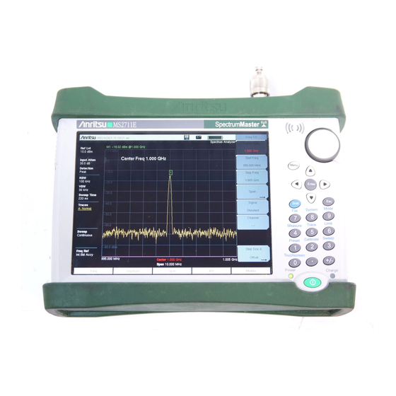
2-4 Front Panel Overview Instrument Overview To turn on the Spectrum Master, press the green On/Off button on the front panel (Figure 2-1) Speaker Rotary Knob Fan Inlet Port Fan Exhaust Port Touch Screen Submenu Keys Menu Key Enter Key and Arrow Keys Esc (Escape) Key Shift Key Numeric Keypad/... -
Page 27: Front Panel Keys
Instrument Overview 2-4 Front Panel Overview Front Panel Keys Menu Key Press the Menu key to display a grid of shortcut icons for installed measurement modes and user selected menus and setup files. Figure 2-2 shows the Menu key screen with shortcut icons for the installed measurement modes. - Page 28 2-4 Front Panel Overview Instrument Overview Press and hold down any key for a few seconds to add a shortcut to this screen.To shortcut setup files (.stp), open the recall menu and hold down on the file name for several seconds. Then select the location for the shortcut.
-
Page 29: Touch Screen Keys
Instrument Overview 2-4 Front Panel Overview Shift Key Pressing the Shift key and then a number key executes the function that is indicated in blue text above the number key. When the Shift key is active, its icon is displayed at the top-right of the measurement display area by the battery charge indicator. -
Page 30: Led Indicators
2-5 Display Overview Instrument Overview LED Indicators Power LED The Power LED is located to the left of the On/Off key. The LED is solid green when the unit is on and slowly blinks when the unit is off but has external power. Charge LED The Charge LED is located to the right of the On/Off key. - Page 31 Instrument Overview 2-5 Display Overview In addition to the default color display, Spectrum Master offers the following display settings for the Spectrum Analyzer, Interference Analyzer, Channel Scanner, AM/FM/PM Analyzer, Power Meter, and High Accuracy Power Meter modes: Black & White for printing and viewing in broad daylight conditions Night Vision optimized for night-time viewing High Contrast for other challenging viewing conditions Default Colors...
-
Page 32: Test Panel Connector Overview
2-6 Test Panel Connector Overview Instrument Overview Test Panel Connector Overview Test panel connector for the Spectrum Master is shown in Figure 2-7. Analyzer/RF In External External Trigger USB Mini-B Reference External Power Generator/RF Out Headset Jack USB Type A (Option 20) Figure 2-7. -
Page 33: Symbols And Indicators
Instrument Overview 2-7 Symbols and Indicators Headset Jack The headset jack provides audio output from the built-in AM/FM/SSB demodulator for testing and troubleshooting wireless communication systems. The jack accepts a 2.5 mm 3-wire miniature phone plug such as those commonly used with cellular telephones. External Trigger In A TTL signal that is applied to the External Trigger female BNC input connector causes a single sweep to occur. -
Page 34: Additional Symbols
The green Charge LED flashes when the battery is charging, and remains on steady when the battery is fully charged. Caution Use only Anritsu-approved batteries, adapters, and chargers with this instrument. When operating from external power without a battery installed, the battery symbol is replaced by a red plug body (Figure 2-10). -
Page 35: Data Entry
Instrument Overview 2-8 Data Entry Data Entry Numeric Values Numeric values are changed using the rotary knob, arrow keys, or the keypad. Pressing one of the main menu keys will display a list of submenus on the right side of the touch screen. When the value on a submenu key is displayed in red, it is ready for changing. -
Page 36: Mode Selector Menu
2-9 Mode Selector Menu Instrument Overview Mode Selector Menu To access the functions under the Mode menu, select the Shift key, then the Mode (9) key. Use the directional arrow keys, the rotary knob, or the touch screen to highlight the selection, and press the Enter key to select. -
Page 37: Chapter 3-Quick Start Guide
Chapter 3 — Quick Start Guide Introduction This chapter provides a brief overview of basic measurement setups. For detailed measurement information, refer to a specific measurement guide listed in Appendix A, “Measurement Guides”. This chapter provides quick start measurement information for the Spectrum Analyzer mode: Measurement Mode Selection Press the Menu key and use the touch screen to select the appropriate measurement icon. -
Page 38: Spectrum Analyzer
3-3 Spectrum Analyzer Quick Start Guide Spectrum Analyzer Set the instrument to Spectrum Analyzer mode as described in Section 3-2 “Measurement Mode Selection” on page 3-1. Set the Frequency Set Start and Stop Frequencies 1. Press the Freq main menu key. 2. -
Page 39: Set The Measurement Frequency Bandwidth
Quick Start Guide 3-3 Spectrum Analyzer 5. Set the Freq Offset to 0 Hz to remove the frequency offset. The Freq Offset will affect the displayed values of frequencies, Markers and Limits. Note The currently frequency offset value is displayed on the Freq Offset submenu key, located under the Freq main menu >... -
Page 40: Reference Level Offset For External Loss Or External Gain
3-3 Spectrum Analyzer Quick Start Guide Reference Level Offset for External Loss or External Gain To obtain accurate measurements, compensate for any external attenuation or gain by using the RL Offset submenu. The compensation factor is in dB. External attenuation can be created by using an external cable or an external high power attenuator, external gain is typically from an amplifier. -
Page 41: Create A Limit Envelope
Quick Start Guide 3-3 Spectrum Analyzer Create a Limit Envelope 1. Press Shift then Limit (6) to open the Limit menu. 2. Select Limit Envelope. 3. Press the Create Envelope key. Figure 3-2. Limit Envelope Spectrum Master User Guide PN: 10580-00328 Rev. E... -
Page 42: Setting Up Markers
3-3 Spectrum Analyzer Quick Start Guide Setting Up Markers Press the Marker main menu key to display the Marker menu. Selecting, Activating, and Placing a Marker 1. Press the Marker 1 2 3 4 5 6 submenu key and then select the desired marker using the touch screen marker buttons. -
Page 43: Select A Measurement Type
Quick Start Guide 3-3 Spectrum Analyzer Select a Measurement Type In Spectrum Analyzer mode, press Shift then Measure (4) and select a measurement using the submenu keys. Figure 3-4. Spectrum Analyzer Measure Menu Spectrum Master User Guide PN: 10580-00328 Rev. E... - Page 44 3-3 Spectrum Analyzer Quick Start Guide PN: 10580-00328 Rev. E Spectrum Master User Guide...
-
Page 45: Chapter 4-File Management
Chapter 4 — File Management Introduction This chapter will review the file management features of the Spectrum Master and detail the File menu. The submenus under this menu allow the user to save, recall, copy, and delete files in internal memory or an external USB flash drive. Managing Files Press the Shift key then the File (7) key on the numeric keypad to list the File menu. -
Page 46: Save Dialog Box
4-2 Managing Files File Management Save a Measurement Screen as JPEG Press the Save submenu key, type a name for the JPEG file, confirm that the file type is Jpeg, and press Enter to save. Save Dialog Box The save dialog box (Figure 4-1) is used to store files on the internal memory or an external flash drive. -
Page 47: Recall Files
File Management 4-2 Managing Files Recall Files The recall menu enables you to view all the Measurement and Setup files in the internal memory and external USB flash drive. You can sort the recall menu by name, date, or type. You can also select to view only measurement files or setup files by pressing File Type on the Recall dialog box and selecting the file type you want to view. -
Page 48: Copying Files
4-2 Managing Files File Management Copying Files The steps below detail copying a file from internal memory to an external flash drive. Select the files to copy in the top window and the location for the files to be copied to in the bottom window (Figure 4-3). -
Page 49: Deleting Files
File Management 4-2 Managing Files Deleting Files Delete a Selected File or Files Press the Delete submenu key. Highlight the file to be deleted with the touchscreen or the Up/Down arrow keys. Press the Select or De-Select key. The file will be outlined in blue when selected. -
Page 50: File Menu Overview
4-3 File Menu Overview File Management File Menu Overview Open this menu by pressing the Shift key, then the File (7) key. File Save Measurement As FileName.spa Save Save Measurement Setup Save Vary by Measurement Spectrum Measurement Save Mode Analyzer Save On... -
Page 51: File Menu
File Management 4-4 File Menu File Menu Key Sequence: File Save Measurement As: This key will save the current setup with a user File defined file name. The default file name is changed using the Save submenu. To change the default file name, type in a new file with the touch Save Measurement As screen keyboard and press Enter. -
Page 52: Save Menu
4-4 File Menu File Management Save Menu Key Sequence: File > Save The top keys in the Save menu will display the available save options based Save on the current measurement mode. Options include: Setup: Setup files contain basic instrument information, Setup measurement mode setup details, measurement marker data, and limit data. -
Page 53: Save Location Menu
File Management 4-4 File Menu Save Location Menu Key Sequence: File > Save > Change Save Location This menu and dialog box is used to create folders and select where the Save Location Spectrum Master will save the current file. Select folders or drives with the Up/Down keys, the rotary knob or the touch screen. -
Page 54: Save On Event Menu
4-4 File Menu File Management Save On Event Menu Key Sequence: File > Save On Event In Spectrum Analyzer mode, this menu is used to auto save measurements Save On... to internal memory after: ...Crossing Limit ...Crossing Limit: Toggling this submenu key to On will save the measurement to internal memory when the measurement has crossed a defined limit line created with the Limit menu. -
Page 55: Recall Menu
File Management 4-4 File Menu Recall Menu Key Sequence: File > Recall This menu and dialog box is used to navigate folders and select files to Recall recall to the Spectrum Master. Select folders or files with the Up/Down keys, the rotary knob, or the touch screen. Sort By Sort By: Press this submenu key to sort file and folders by the file name, Name... -
Page 56: Copy Menu
4-4 File Menu File Management Copy Menu Key Sequence: File > Copy This menu and dialog box is used to copy folders and files. Select folders or Copy files with the Up/Down keys, the rotary knob or the touch screen. Figure 4-3 on page 4-4 shows the Copy dialog box with two JPG images and one... -
Page 57: Delete Menu
File Management 4-4 File Menu Delete Menu Key Sequence: File > Delete This menu and dialog box is used to delete folders and files. Select folders Delete or files with the Up/Down keys, the rotary knob or the touch screen. Sort By Sort By: Press this submenu key to sort files and folders by name, by the type of file, or by the date that the file or folder was saved. - Page 58 4-4 File Menu File Management 4-14 PN: 10580-00328 Rev. E Spectrum Master User Guide...
-
Page 59: Chapter 5-System Operations
Chapter 5 — System Operations Introduction This chapter will review the Spectrum Master system operations. • “System Menu Overview” on page 5-2 • “System Menu” on page 5-3 • “Preset Menu” on page 5-8 • “Self Test” on page 5-8 •... -
Page 60: System Menu Overview
5-2 System Menu Overview System Operations System Menu Overview To access the functions under the System menu, select the Shift key, then the System (8) key. System System Options Date Status & Time Self GPS Info Test Application GPS Voltage Self Language Test... -
Page 61: System Menu
System Operations 5-3 System Menu System Menu Key Sequence: Shift, System (8) Status: Pressing this submenu key displays the current system status, System including the operating system and firmware versions, temperatures and other details such as current battery information. Press Esc or Enter to return to normal operation. -
Page 62: System Options Menu
5-3 System Menu System Operations System Options Menu Key Sequence: Shift, System (8) > System Options Date and Time: This key brings up a dialog box for setting the current date System Options and time. Use the submenu keys or the Left/Right arrow keys to select the field to be modified. -
Page 63: System Options 2/2 Menu
System Operations 5-3 System Menu System Options 2/2 Menu Key Sequence: Shift, System (8) > System Options > More Center Freq Share: Select All Modes to have the current center frequency System Options 2/2 setting carried over when changing measurement modes. This feature is not applicable to measurements which do not have a center frequency setting or Share CF &... -
Page 64: Display Settings Menu
5-3 System Menu System Operations Display Settings Menu Key Sequence: Shift, System (8) > System Options > Display Brightness: The brightness of the display can be adjusted to optimize Display Settings viewing under a wide variety of lighting conditions. Use the keypad, the Up/Down arrow keys or the rotary knob to select a brightness level from 1 to Brightness 9, with 9 being the brightest. -
Page 65: Reset Menu
System Operations 5-3 System Menu Reset Menu Key Sequence: Shift, System (8) > System Options > Reset Factory Defaults: Restores the instrument to the factory default values, Reset including Ethernet (Option 411), language, volume, brightness setting, and user created shortcut icons on the Menu screen. Press the Enter key to Factory initiate the reset, and power-cycle the instrument. -
Page 66: Preset Menu
If the Spectrum Master is within the specified operating range with a charged battery, and the self test fails, then contact your Anritsu Service Center (http://www.anritsu.com/Contact.asp). To start a self test when the system is already powered up: 1. -
Page 67: Updating The Spectrum Master Firmware
Note The “Release History” link provides a summary of the firmware changes. 1. Click on the “Firmware Update for the Spectrum Master MS2711E” link. 2. Click the “Download” button and then “Run”. After the download is complete, press “Run” again and follow the onscreen instructions. Press “Help (?)” for additional information. - Page 68 5-6 Updating the Spectrum Master Firmware System Operations 5-10 PN: 10580-00328 Rev. E Spectrum Master User Guide...
-
Page 69: Chapter 6-Gps (Option 31)
(parts per billion). No accuracy specifications apply if no GPS satellites are acquired. In order to acquire data from the GPS satellites, the user must have line-of-sight to the satellites or the antenna must be placed outside without any obstructions. An Anritsu GPS antenna is required. - Page 70 6-3 Activating the GPS Feature GPS (Option 31) 4. When the GPS receiver has tracked at least three satellites, the GPS icon will change to GREEN. Latitude and Longitude information is displayed in the white bar on top of the display.
-
Page 71: Saving And Recalling Traces With Gps Information
GPS (Option 31) 6-4 Saving and Recalling Traces with GPS Information Saving and Recalling Traces with GPS Information Saving Traces with GPS Information The GPS coordinates of a location can be saved along with a measurement trace. Refer to the “Save Menu”... -
Page 72: Gps Menu
Short/Open: A short or open exists between the antenna and the connection. If this message is displayed, then remove and replace the GPS antenna. If the message persists, then try another Anritsu GPS antenna. If the message persists, then contact your nearest Anritsu Service Center. -
Page 73: Chapter 7-Master Software Tools
MST software Help drop-down menu, Help Contents. MST Overview Anritsu Master Software Tools is a Windows 2000 and later compatible program for transferring and editing saved measurements, markers, and limit lines to a PC. Master Software Tools will not function on earlier versions of the Microsoft Windows operating system. -
Page 74: Feature Overview
(only Spectrum Analyzer measurements). • Modify instrument’s Cable list, Antenna list, and Signal Standard list. • Trace Math functions. • Convert DAT files from Anritsu Handheld Software Tools into Anritsu Master Software Tools file formats Editing Graphs MST can be used to change the scale, limit lines, and markers in a measurement through the Edit Graph button in the workspace toolbar, or through the Context Menus. - Page 75 Master Software Tools 7-2 MST Overview Folder Spectrogram Folder Spectrogram provides a simulated three dimensional view of a large amount of data in one set of graphs. • Traces can be viewed as a waterfall, 3D, or .avi movie. • View 3D data in Time Domain or Frequency Domain. •...
- Page 76 PC. • Establish a direction connection from a PC using USB or a direct Ethernet connection. • Update the instrument with the latest firmware available from: http://www.anritsu.com. Figure 7-4. Remote Access Tool Connecting to a Networked Instrument...
-
Page 77: Installing Mst
MST is provided on the CD-ROM included with the instrument. Insert the CD-ROM into a PC to run the installer. Follow the instruction on the screen. MST is also available as a download from http://www.anritsu.com. Connecting to the Instrument Use the USB cable supplied with the test instrument to make the connection. - Page 78 7-4 Installing MST Master Software Tools PN: 10580-00328 Rev. E Spectrum Master User Guide...
-
Page 79: Appendix A-Measurement Guides
Introduction This appendix provides a list of supplemental documentation for Spectrum Master features and options. These measurement guides are available as PDF files on the documentation disc and the Anritsu web site. Table A-1. Analyzers and Analyzer Options Related Document... - Page 80 Measurement Guides PN: 10580-00328 Rev. E Spectrum Master User Guide...
-
Page 81: Index
....5-7 contacting Anritsu ....1-1 Master Software Tools . - Page 82 ... . 4-12 web site, contacting Anritsu ..1-1 self test ..... .5-3, 5-8 self test, system and application .
- Page 84 Anritsu Company 490 Jarvis Drive Anritsu utilizes recycled paper and environmentally conscious inks and toner. Morgan Hill, CA 95037-2809 http://www.anritsu.com...
Need help?
Do you have a question about the Spectrum Master MS2711E and is the answer not in the manual?
Questions and answers