Advertisement
Quick Links
Advertisement

Related Manuals for Anritsu MS27101A-IBCM


Summary of Contents for Anritsu MS27101A-IBCM
- Page 1 Quick Start Guide MS27101A-IBCM In-Building Coverage Mapper MS27101A, 9 kHz to 6 GHz Anritsu Company Part Number: 10580-00470 490 Jarvis Drive Revision: B Morgan Hill, CA 95037-2809 Published: November 2020 Copyright 2020 Anritsu Company http://www.anritsu.com...
- Page 2 Anritsu Company. Export Management The Anritsu products identified herein and their respective manuals may require an Export License or approval by the government of the product country of origin for re-export from your country. Before you export these products or any of their manuals, please contact Anritsu Company to confirm whether or not these items are export-controlled.
-
Page 3: Table Of Contents
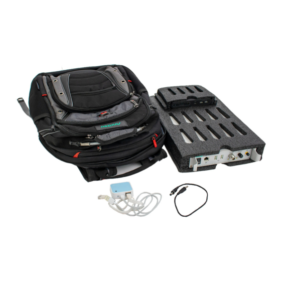
For additional information and literature covering your product, go to the products page of your instrument and select the Library tab here: https://www.anritsu.com/en-US/test-measurement Contacting Anritsu To contact Anritsu, please visit: https://www.anritsu.com/en-US/contact-us QSG-2 Unpacking Contents The components and accessories included in the In-Building Coverage Mapper backpack kit are listed in Table QSG-1. -
Page 4: Equipment Front Panel Interfacing
QSG-3 Equipment Front Panel Interfacing QSG-3 Equipment Front Panel Interfacing The equipment front panels interfaces are shown below for the: • MS27101A Remote Spectrum Monitor • Wireless Travel Router • SM7004 (Omni Power Pack) MS27101A Front Panel The MS27101A is the remote spectrum monitor that performs the signal monitoring. The MS27101A front panel is shown in Figure QSG-1. - Page 5 QSG-3 Equipment Front Panel Interfacing Wireless Travel Router The wireless travel router is used to interface between the MS27101A and the Android application. The wireless travel router front panel is shown below in Figure QSG-2. 1. Powered On Indicator LED 2.
- Page 6 QSG-4 Setting the SM7004 Voltage QSG-4 Setting the SM7004 Voltage The SM7004 is the re-chargeable battery bank that provides DC power to the MS27101A. Set the SM7004 voltage to 12 VDC to operate the MS27101A. Do not adjust the SM7004 to 12 VDC when the SM7005 cable is connected to the MS27101A. Caution Use the steps below to set the SM7004 to 12 VDC before making connection.
-
Page 7: Inserting Into The Sm7009
QSG-5 Inserting Into the SM7009 QSG-5 Inserting Into the SM7009 The MS27101A and the SM7004 are assembled into the SM7009 foam enclosure for performing the In-Building Coverage Mapping as shown in Figure QSG-5. 1. SM7004 2. SM7009 3. MS27101A Figure QSG-5. MS27101A, SM7004, and SM7009 Assembly Ensure the MS27101A and SM7004 fit flush into the SM7009 foam slots as shown in Figure QSG-6. - Page 8 QSG-6 Connecting the Hardware QSG-6 Connecting the Hardware The In-Building Coverage Mapping equipment interface connections are described in this section. Connect the SM7004 The MS27101A rear panel battery jack is accessible through the foam cutout as shown in Figure QSG-7. 1.
-
Page 9: Sm7005
QSG-6 Connecting the Hardware Connect the SM7005 from the SM7004 to the to the MS27101A rear panel battery input jack. Slightly separate the foam side piece from the main battery foam enclosure to form a groove as shown in Figure QSG-8. - Page 10 QSG-6 Connecting the Hardware Connecting the Wireless Travel Router The wireless travel router connects to the MS27101A. Refer to Figure QSG-9. Connect the LAN Ethernet and USB type A cables to the wireless travel router. Connect the wireless travel router USB Type A cable to the USB Type A port on the MS27101A. Connect the wireless travel router LAN Ethernet cable to the Ethernet port on the MS27101A.
- Page 11 Fit the wireless travel router with the Ethernet and USB cable into the netted pouch located inside the backpack as shown in Figure QSG-10. The In-Building Coverage Mapper hardware installation is now complete. For information on Anritsu antennas and antenna applications visit the Anritsu Website at: https://www.anritsu.com/en-US/. Figure QSG-10. Router Fitted Inside Backpack Installing Software Download and install the MA8100A In-building Coverage Mapping with TRX NEON®...
- Page 12 Anritsu Company 490 Jarvis Drive Anritsu utilizes recycled paper and environmentally conscious inks and toner. Morgan Hill, CA 95037-2809 http://www.anritsu.com...
Need help?
Do you have a question about the MS27101A-IBCM and is the answer not in the manual?
Questions and answers