Table of Contents
Advertisement
Quick Links
User Guide
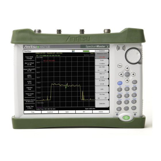
Spectrum Master™ MS271xE
Handheld Spectrum Analyzer
MS2712E, 9 kHz to 4 GHz
MS2713E, 9 kHz to 6 GHz
Appendix A provides a list of supplemental documentation for the
Spectrum Master features and options. The documentation set is
available as PDF files on the documentation disc and the
Anritsu website.
Anritsu Company
490 Jarvis Drive
Morgan Hill, CA 95037-2809
USA
http://www.anritsu.com
Part Number: 10580-00251
Revision: T
Published: May 2016
Copyright 2016 Anritsu Company
Advertisement
Table of Contents

Related Manuals for Anritsu Spectrum Master MS2712E


Summary of Contents for Anritsu Spectrum Master MS2712E
- Page 1 Spectrum Master features and options. The documentation set is available as PDF files on the documentation disc and the Anritsu website. Anritsu Company Part Number: 10580-00251 490 Jarvis Drive Revision: T Morgan Hill, CA 95037-2809 Published: May 2016 Copyright 2016 Anritsu Company http://www.anritsu.com...
-
Page 3: Table Of Contents
Additional Documentation ........1-1 Contacting Anritsu for Sales and Service ..... . . 1-3 Instrument Description . - Page 4 Table of Contents (Continued) Chapter 3—Quick Start Guide Introduction ..........3-1 Measurement Mode Selection .
- Page 5 Anritsu Software Tool Box ........
- Page 6 Table of Contents (Continued) Chapter 9—Web Remote Control Introduction ..........9-1 Setup .
-
Page 7: Chapter 1-General Information
Chapter 1 — General Information Introduction The Spectrum Master User Guide is part of a set of manuals that cover all of the instrument functions and their use. This manual covers the instrument overview, system functions, and other common features, along with a brief guide to basic measurement concepts and setups. Most instrument operations and modes are covered in specific measurement guides as listed below. - Page 8 1-1 Introduction General Information Document Part Number Description (Required Option) 3GPP2 Signal Analyzer Measurement Guide CDMA RF Measurements (Option 42) CDMA Demodulation (Option 43) CDMA Over-the-Air Measurements (Option 33) 10580-00235 EV-DO RF Measurements (Option 62) EV-DO Demodulation (Option 63) EV-DO Over-the-Air Measurements (Option 34) CDMA/EV-DO Measurements (Option 884) WiMAX Signal Analyzer Measurement Guide Fixed WiMAX RF Measurements (Option 46)
-
Page 9: Contacting Anritsu For Sales And Service
• http://www.anritsu.com/en-US/test-measurement/products/ms2713e Contacting Anritsu for Sales and Service To contact Anritsu, visit the following URL and select the services in your region: http://www.anritsu.com/contact-us Instrument Description The Spectrum Master MS2712E and MS2713E are integrated multi-functional test instruments that eliminate the need to carry and learn multiple test sets. The Spectrum... -
Page 10: Available Models
MS2712E-0099 MS2713E-0099 test data Ethernet Connectivity (cannot be ordered with Option MS2712E-0411 MS2713E-0411 57 or 79) MS2712E-0431 MS2713E-0431 Coverage Mapping (requires Option 31) EMF Measurements (requires Anritsu Isotropic MS2712E-0444 MS2713E-0444 Antenna) MS2712E-0509 MS2713E-0509 AM/FM/PM Analyzer MS2712E-0751 MS2713E-0751 CPRI RF Measurements... - Page 11 General Information 1-2 Instrument Description Table 1-2. Available Options (Sheet 2 of 4) MS2712E MS2713E Description W-CDMA/HSPA+ RF Measurements (cannot be MS2712E-0044 MS2713E-0044 ordered with Option 881) W-CDMA/HSPA+ Demodulation (cannot be ordered MS2712E-0065 MS2713E-0065 with Option 881) W-CDMA/HSPA+ Over-the-Air Measurements MS2712E-0035 MS2713E-0035 (Option 31 recommended.
- Page 12 1-2 Instrument Description General Information Table 1-2. Available Options (Sheet 3 of 4) MS2712E MS2713E Description LTE/LTE-A FDD/TDD Measurements (requires Option 31 for full functionality. Combines functionality MS2712E-0883 MS2713E-0883 of Options 541, 542, 546, 551, 552, and 556. Cannot be ordered with Option 541, 542, 546, 551, 552, or 556) CDMA RF Measurements (cannot be ordered with...
-
Page 13: Calibration And Verification
Calibration and Verification Anritsu recommends an annual calibration and performance verification of the Spectrum Master by local Anritsu service centers. The Spectrum Master is self-calibrating and there are no field-adjustable components. Contact information for Anritsu Service Centers is available at http://www.anritsu.com/contact-us. -
Page 14: Esd Caution
1-4 Instrument Care and Preventive Maintenance General Information Connecting Procedure 1. Carefully align the connectors. The male connector center pin must slip concentrically into the contact fingers of the female connector. 2. Push connectors straight together. Do not twist or screw them together. A slight resistance can usually be felt as the center conductors mate. -
Page 15: Battery Replacement
Adapter, or outside the Spectrum Master with the optional Dual Battery Charger. Refer to “Symbols and Indicators” on page 2-8 for a description of battery symbols. Use only Anritsu Company approved batteries, adapters, and chargers with this Note instrument. Anritsu recommends removing the battery for long-term storage of the instrument. -
Page 16: Secure Environment Workplace
1-5 Secure Environment Workplace General Information When using the Automotive Power Adapter, always verify that the supply is rated for a minimum of 60 Watts @ 12 VDC, and that the socket is clear of any dirt or Caution debris. If the adapter plug becomes hot to the touch during operation, discontinue use immediately. -
Page 17: Erase All User Files In Internal Memory
General Information 1-5 Secure Environment Workplace Erase All User Files in Internal Memory Perform a Master Reset: 1. Turn the instrument on. 2. Press the Shift button, then the System (8) button. 3. Press the System Options submenu key. 4. Press the Reset key, then the Master Reset key. A message box will be displayed to warn the user that all settings will be returned to factory default values and all user files will be deleted. - Page 18 1-5 Secure Environment Workplace General Information 1-12 PN: 10580-00251 Rev. T MS2712E/13E User Guide...
-
Page 19: Chapter 2-Instrument Overview
This chapter provides an overview of the Anritsu Spectrum Master. It describes the instrument front panel, touch screen display, and the connector panel. For detailed information on the instrument’s test and measurement functions, refer to one of the Anritsu user documents listed in Appendix A, “Measurement... -
Page 20: Instrument Front Panel
2-3 Instrument Front Panel Instrument Overview Instrument Front Panel uses a touch screen and keypad for data input. See Figure 2-1. The five Spectrum Master bottom menu keys and up to eight submenu keys on the right side of the display are touch screen keys. -
Page 21: Front Panel Keys
Instrument Overview 2-3 Instrument Front Panel Front Panel Keys The numeric keypad, rotary knob, and the four arrow keys can all be used to change the value of the currently selected parameter. Numeric Keypad Keys 0 through 9 are used for numeric input, with an alternate function printed in blue above each of the keys. - Page 22 2-3 Instrument Front Panel Instrument Overview Menu Key The Menu key displays a grid of shortcut icons for installed measurement modes and user-selected menus and setup files. See Figure 2-3. Press one of the icons in the top three rows to change modes. These icons are preinstalled and cannot be moved or deleted. An alternative to the Menu key is to press Shift, then the Mode (9) key to display the Mode Selector list box.
- Page 23 Instrument Overview 2-3 Instrument Front Panel User-Created Shortcuts To create a shortcut to any submenu key or main menu key, press and hold the key until a grid appears, showing the open locations on the Menu screen where you can place the new shortcut.
-
Page 24: Interface Screen
2-4 Interface Screen Instrument Overview Interface Screen Figure 2-6 illustrates the Spectrum Master interface screen in Spectrum Analyzer mode, with touch screen menu keys, title bar, and measurement settings and results around the graph area, or sweep window. Save Battery GPS Icon Charge Save... -
Page 25: Symbols And Icons On The Title Bar
Use only Anritsu-approved batteries, adapters, and chargers with this instrument. Caution Anritsu Company recommends removing the battery for long-term storage of the instrument. The Shift icon is displayed after the Shift key is pressed, and it remains displayed until another button is pressed. -
Page 26: Symbols And Indicators
2-4 Interface Screen Instrument Overview Symbols and Indicators The following symbols, icons, and indicators convey the instrument status or condition on the display. The colors shown here are in the standard or default display mode. Table 2-1. Symbols and Icons Symbol Description Green: Battery is 30% to 100% charged. -
Page 27: Display Settings
Instrument Overview 2-4 Interface Screen Display Settings The Display Settings submenu lets you adjust the screen brightness level and control the auto-dimming function. Refer to “Brightness Settings Menu” on page 5-8. You can also turn off the display entirely, as described in “Display Settings Menu”... -
Page 28: Touch Screen Calibration
2-4 Interface Screen Instrument Overview Touch Screen Calibration Calibration optimizes the response of touch input. It is recommended if the instrument does not respond as expected when you press the touch screen. The Calibrate Touch Screen submenu key is in the “System Menu”... - Page 29 *.spa measurement file. To return to normal touch entry mode, reboot the instrument (turn power Off, then On). If your touch screen has been damaged, refer to “Contacting Anritsu for Sales and Service” on page 1-3. Figure 2-11. Arrow Navigation Example MS2712E/13E User Guide PN: 10580-00251 Rev.
-
Page 30: Data Entry
2-5 Data Entry Instrument Overview Data Entry User input can be in the form of numeric values for instrument or measurement settings, selected values from a preset list, or alphanumeric text when entering file names, for example. To view or change a parameter value, access the appropriate submenu by pressing one of the five main menu keys along the bottom of the interface screen, then navigating through the touch screen submenus. -
Page 31: Text Entry
Instrument Overview 2-5 Data Entry Text Entry When an instrument function requires you to enter text, such as a name for a measurement or setup file you wish to save, a touch screen keyboard is displayed. See Figure 2-12. Digits can be entered using the touch screen keyboard or the front panel keypad. -
Page 32: Mode Selector
2-6 Mode Selector Instrument Overview Mode Selector To change to another operation or measurement mode, press Shift, then the Mode (9) key to display the Mode Selector list box, illustrated in Figure 2-13. Use the directional arrow keys or the rotary knob to highlight the desired mode, then press Enter to switch to the selected application. -
Page 33: Connector Panel
Instrument Overview 2-7 Connector Panel Connector Panel The Spectrum Master connector panel is illustrated in Figure 2-14. Figure 2-14. Spectrum Master Connector Panel External Reference In External Trigger In Analyzer/RF In (Type N) USB Mini-B GPS Type SMA (Option 31) External Power USB Type A Headset jack... - Page 34 The first time the Spectrum Master is connected to a PC, the normal USB device detection by the computer operating system will take place. For proper detection, the applicable Anritsu Software Tool should be installed on Note the PC prior to connecting the Spectrum Master to the USB port.
- Page 35 Instrument Overview 2-7 Connector Panel To prevent damage to your instrument, do not use pliers or a plain wrench to tighten the SMA connector. Do not over-tighten the connector. The recommended torque is 8 lbf·in (0.9 N·m or 90 N·cm). External Power This is a 2.1 mm by 5.5 mm barrel connector, 12.5 to 15 VDC, <...
- Page 36 2-7 Connector Panel Instrument Overview LAN Connection (Option 411) The RJ-45 connector is used to connect the Spectrum Master to a local area network or directly to a PC with an Ethernet crossover cable. Integrated into this connector are two LEDs.
-
Page 37: Soft Carrying Case
Instrument Overview 2-8 Soft Carrying Case Soft Carrying Case The Spectrum Master can be operated while in the soft carrying case. On the back of the case is a large storage pouch for accessories and supplies. To install the instrument into the soft carrying case: 1. -
Page 38: Tilt Bail Stand
2-9 Tilt Bail Stand Instrument Overview The soft carrying case includes a detachable shoulder strap, which can be connected to the D-rings of the case. The soft case has panel openings for the fan inlet and exhaust ports. Do not block Caution the air flow through the panels when the unit is operating. -
Page 39: Chapter 3-Quick Start Guide
Chapter 3 — Quick Start Guide Introduction This chapter provides a brief overview of basic measurement setups. For detailed descriptions of measurement functions and settings, refer to the appropriate Measurement Guide as listed Appendix Measurement Mode Selection Press the Menu key, then press the shortcut icon for the desired application, or measurement mode. -
Page 40: Spectrum Analyzer
3-3 Spectrum Analyzer Quick Start Guide Spectrum Analyzer Set the instrument to Spectrum Analyzer mode as described in Section 3-2 “Measurement Mode Selection” on page 3-1. Set the Frequency Set Start and Stop Frequencies 1. Press the Freq main menu key. 2. -
Page 41: Set The Measurement Frequency Bandwidth
Quick Start Guide 3-3 Spectrum Analyzer 4. Offset will be displayed at the bottom of the screen. The Center Freq, Start Freq, and Stop Freq keys will also indicate that a frequency offset has been turned on. 5. Set the Freq Offset to 0 Hz to remove the frequency offset. The Freq Offset will affect the displayed values of frequencies, Markers and Limits. -
Page 42: Reference Level Offset For External Loss Or External Gain
3-3 Spectrum Analyzer Quick Start Guide Reference Level Offset for External Loss or External Gain To obtain accurate measurements, compensate for any external attenuation or gain by using the RL Offset submenu. The compensation factor is in dB. External attenuation can be created by using an external cable or an external high power attenuator, external gain is typically from an amplifier. -
Page 43: Create A Limit Envelope
Quick Start Guide 3-3 Spectrum Analyzer Create a Limit Envelope 1. Press Shift, then Limit (6) to display the Limit menu. 2. Select Limit Envelope. 3. Press the Create Envelope key. Figure 3-2. Limit Envelope MS2712E/13E User Guide PN: 10580-00251 Rev. T... -
Page 44: Setting Up Markers
3-3 Spectrum Analyzer Quick Start Guide Setting Up Markers Press the Marker main menu key to display the Marker menu. Selecting, Activating, and Placing a Marker 1. Press the Marker 1 2 3 4 5 6 submenu key and then select the desired marker using the touch screen marker buttons. -
Page 45: Select A Measurement Type
Quick Start Guide 3-3 Spectrum Analyzer Select a Measurement Type In Spectrum Analyzer mode, press Shift, then Measure (4) and select a measurement using the submenu keys. Figure 3-4. Spectrum Analyzer Measure Menu MS2712E/13E User Guide PN: 10580-00251 Rev. T... -
Page 46: External Power On
3-3 Spectrum Analyzer Quick Start Guide External Power On The When DC Applied setting in the Power-On menu allows the instrument to restart automatically when external DC power is applied to the connector shown in Figure 2-14 on page 2-15. Refer to “External Power”... -
Page 47: Chapter 4-File Management
Chapter 4 — File Management Introduction This chapter describes the file management features of the Spectrum Master and the related touch screen menus. The File menu and its submenus allow you to save, recall, copy, and delete files in internal memory or an external USB flash drive. Managing Files Press the Shift key, then the File (7) key on the numeric keypad to display the File menu. -
Page 48: Save Files
4-2 Managing Files File Management Save Files The submenu keys that are available for file management may vary with instrument options and measurement modes. Refer to “File Menu” on page 4-9. Save Measurement As The Save Measurement As submenu key provides a one-touch method of saving the current measurement data. - Page 49 File Management 4-2 Managing Files Save Dialog Box In the Save dialog, use the touch screen keyboard to enter the name of the file to save. See Figure 4-1 on page 4-2. Optionally, you can use the Quick Name keys to insert preset text strings into the file name.
- Page 50 4-2 Managing Files File Management Change Save Location You can save files to internal memory or to an external USB flash drive. To change the destination location of the saved file, press the Change Save Location submenu key under the Save menu.
-
Page 51: Recall Files
File Management 4-2 Managing Files Recall Files Press the Recall Measurement key or the Recall key under the File menu to recall a previously saved file from internal memory or an external USB drive, if connected. The files listed in the Recall dialog box depend on the file type selected. -
Page 52: Copy Files
4-2 Managing Files File Management Copy Files Press the Copy key under the File menu to open the Copy dialog box and menu, where you can copy a single or multiple files or folders. The source and destination locations may be the instrument’s internal memory or an external USB drive, if connected. -
Page 53: Delete Files
File Management 4-2 Managing Files 8. Press the Scroll key to switch navigation control to the Dst (destination) pane. Alternatively, you can directly press a folder in the bottom pane to select it. 9. If the destination folder is off the screen, use the rotary knob or the Up/Down arrow keys to locate and select it. -
Page 54: File Menu Overview
4-3 File Menu Overview File Management File Menu Overview Open this menu by pressing the Shift key, then the File (7) key. File Save Measurement As FileName_1.spa Save Save Measurement Equivalent to pressing the screen shortcut Save Restore Default Quick Spectrum Save Name Buttons... -
Page 55: File Menu
File Management 4-4 File Menu File Menu Key Sequence: Shift > File (7) Save Measurement As: Pressing this key will save instrument setup File parameters, trace data, and any measurement results to the file that is named on the submenu key. Upon Save completion, the file name numerical Save Measurement As suffix increments by 1 and will be applied to the next Save. -
Page 56: Save Menu
4-4 File Menu File Management Save Menu Key Sequence: Shift > File (7) > Save Measurement Key Sequence: Shift > File (7) > Save Save Restore Default Quick Name Buttons: Press this submenu key to undo any Quick Names previously entered and return all Quick Name buttons to Restore factory defaults. -
Page 57: File Type Menu
File Management 4-4 File Menu File Type Menu Key Sequence: Shift > File (7) > Save Measurement > Change Type Key Sequence: Shift > File (7) > Save > Change Type File Type JPEG Capture Full Graph Only: Press this submenu key to toggle between file types, Full JPEG Capture and Graph Only. -
Page 58: Save On
4-4 File Menu File Management Save On... Menu Key Sequence: Shift > File (7) > Save On Event In Spectrum Analyzer mode, this menu is used to automatically save measurements to the current save location after any of the following events: Save On... -
Page 59: Recall Menu
File Management 4-4 File Menu Recall Menu Key Sequence: Shift > File (7) > Recall Recall Sort By Sort By Name Type Date: Press this submenu key to choose the item by which folders and files are sorted in the Recall dialog box. See Figure 4-5 Name Type... -
Page 60: Copy Menu
4-4 File Menu File Management Copy Menu Key Sequence: Shift > File (7) > Copy Sort By Copy Name Type Date: Press this submenu key to choose the item by which Sort By folders and files are sorted in the Copy dialog box. See Figure 4-6 on page 4-6. -
Page 61: Delete Menu
File Management 4-4 File Menu Delete Menu Key Sequence: Shift > File (7) > Delete Delete Sort By Sort By Name Type Date: Press this submenu key to choose the item by which folders and files are sorted in the Delete dialog box. See Figure 4-7 Name Type... - Page 62 4-4 File Menu File Management 4-16 PN: 10580-00251 Rev. T MS2712E/13E User Guide...
-
Page 63: Chapter 5-System Operations
Chapter 5 — System Operations Introduction This chapter reviews the Spectrum Master system operations and related menus. The other menus (Sweep, Measure, Trace, and Limit) are described in the Measurement Guides listed Appendix MS2712E/13E User Guide PN: 10580-00251 Rev. T... -
Page 64: System Menu Overview
5-2 System Menu Overview System Operations System Menu Overview To access the System menu functions, press the Shift key, then the System (8) key. Requires Option 31 System Display Settings System Options Brightness Settings Date Status Brightness & Brightness Time Self Ethernet Auto Dim... -
Page 65: System Menu
Application If the self test fails when the battery is fully charged and the instrument is Self within the specified operating temperature, contact your Anritsu Service Test Center and report the test results. Application Self Test: This key initiates a series of diagnostic tests related to the performance of the instrument for specific applications. -
Page 66: System Options Menu
5-3 System Menu System Operations System Options Menu Key Sequence: Shift, System (8) > System Options Date and Time: Press this submenu key to display a dialog box for setting System Options the current date and time. Use the submenu keys or the Left/Right arrow keys to select the field to be modified. -
Page 67: System Options 2/2 Menu
System Operations 5-3 System Menu System Options 2/2 Menu Key Sequence: Shift, System (8) > System Options > More Share CF & Pwr Offset All Modes Not Shared: Press this submenu key to toggle the setting System Options 2/2 between All Modes and Not Shared. Select All Modes to have the current Share CF &... -
Page 68: Power-On Menu
5-3 System Menu System Operations Figure 5-5. Remote Access Password Dialog Power-On Menu Key Sequence: Shift, System (8) > System Options > More > Power–On Power–On Power Switch: Press this submenu key to set the instrument for normal use Power Switch of the On/Off button on the instrument front panel. -
Page 69: Display Settings Menu
System Operations 5-3 System Menu Display Settings Menu Key Sequence: Shift, System (8) > System Options > Display Brightness: Opens the “Brightness Settings Menu” on page 5-8. Display Settings Display Blank: Opens the message box illustrated in Figure 5-8. Press Enter to turn off the display, or press Esc to abort. -
Page 70: Brightness Settings Menu
5-3 System Menu System Operations Brightness Settings Menu Key Sequence: Shift, System (8) > System Options > Display > Brightness The brightness of the display can be adjusted to optimize viewing under a wide variety of lighting conditions. Brightness Settings Brightness: Press this submenu key to open the Brightness Editor window, where you can adjust the display brightness level from 0 to 100, with 100 Brightness... -
Page 71: Reset Menu
System Operations 5-4 Preset Menu Reset Menu Key Sequence: Shift, System (8) > System Options > Reset Factory Defaults: Press this submenu key to restore the instrument to its Reset factory default settings, including Ethernet (Option 411), language, volume, and brightness settings. The instrument will power cycle as part of this Factory operation. -
Page 72: Self Test
If the Spectrum Master is within the specified operating range with a charged battery and the self test fails, contact your Anritsu Service Center at: http://www.anritsu.com/contact-us. To initiate a self test when the system is already powered up: 1. -
Page 73: Updating The Spectrum Master Firmware
5-6 Updating the Spectrum Master Firmware Updating the Spectrum Master Firmware The Spectrum Master is updated using a USB memory stick. Updated product information can be found on the Anritsu website: http://www.anritsu.com/en-US/test-measurement/mobile-wireless-communications/spectrum- analyzers Search for the product model number and click the link. On the product page, press the Downloads link, then click the Drivers/Firmware/Software tab. - Page 74 5-6 Updating the Spectrum Master Firmware System Operations 5-12 PN: 10580-00251 Rev. T MS2712E/13E User Guide...
-
Page 75: Chapter 6-Gps (Option 31)
Chapter 6 — GPS (Option 31) Introduction The Spectrum Master is available with a built-in GPS receiver feature (Option 31) that can provide latitude, longitude, altitude, and UTC timing information. This option also enhances frequency reference oscillator accuracy in the spectrum analyzer mode. When GPS is actively locked to satellites, this information is saved with all saved measurements and can be displayed with Master Software Tools. - Page 76 6-2 Activating the GPS Feature GPS (Option 31) 4. When the GPS receiver is tracking at least four satellites, the GPS icon changes to green. Latitude and longitude information is displayed in the title bar at the top of the display.
-
Page 77: Resetting Gps
GPS (Option 31) 6-3 Resetting GPS Resetting GPS To reset the GPS, press the Reset submenu key. The green GPS icon shows a red cross mark when satellite tracking is lost after tracking four or more satellites. The GPS latitude and longitude are saved in the instrument memory until the Spectrum Master is turned off or until GPS is turned off by using the GPS On/Off key. -
Page 78: Gps Menu
Short/Open: If an active antenna is in use, a short or open exists between the antenna and the connection. If this message is displayed, replace the antenna. If the message persists, try another Anritsu GPS antenna. If needed, contact your nearest Anritsu Service Center. If a passive antenna is in use, the message should display: Antenna OPEN Detected or Passive Antenna Used. -
Page 79: Chapter 7-Bias Tee (Option 10)
Chapter 7 — Bias Tee (Option 10) Overview Option 10 provides a bias tee that is installed inside the instrument. The bias arm is connected to a 12 VDC to 32 VDC power source that can be turned on as needed to place the voltage on the center conductor of the instrument’s RF In port. - Page 80 7-1 Overview Bias Tee (Option 10) PN: 10580-00251 Rev. T MS2712E/13E User Guide...
-
Page 81: Chapter 8-Anritsu Tool Box
Chapter 8 — Anritsu Tool Box Introduction The Anritsu Tool Box is a suite of applications that provide an interface between Anritsu handheld RF instruments and a PC. The instrument connects to the computer via a USB, Ethernet, or serial port. Depending on the application selected, available functions range... -
Page 82: Anritsu Software Tool Box
Tool Box Installer on the Anritsu Software DVD Anritsu Software Tool Box The Anritsu Tool Box serves as a central location from which you can open a previously saved measurement, visit the Anritsu website, or launch an application. To open the Tool Box, either double-click the desktop shortcut or select the Tool Box from the Windows Start menu, under All Programs and the Anritsu folder. -
Page 83: Software Tools
Windows Start menu. The following sections list the top features and functions of the tools contained in the Anritsu Tool Box. For a detailed description of these features and how to perform specific tasks, refer to each application’s Help system. -
Page 84: Easytest Tools
Tools easyMap Tools is the new name for Anritsu Map Master. The application allows users to find and prepare geo-referenced maps and to build floor plans suitable for Anritsu Handheld Spectrum Analyzers with Interference Analysis or Coverage Mapping capabilities (Option 25 or Option 431, respectively). -
Page 85: Chapter 9-Web Remote Control
You can connect one or more instruments to any computer with HTML-5 compatible browser. Anritsu strongly recommends using Google Chrome, as other browsers do not fully support HTML-5. The control device may be a laptop, a desktop computer, or a mobile device, including a wide range of tablets and smart phones running Android or iOS operating systems. -
Page 86: Connection To A Wi-Fi Portable Router
9-2 Setup Web Remote Control 5. Set instrument parameters as appropriate, such as measurement mode, frequency range, amplitude. You may skip this step and set up the instrument remotely at a later time, after Ethernet connection has been established. 6. Launch the Google Chrome browser on your PC, laptop, or mobile device. Due to compatibility issues with HTML-5, do not connect using another browser than Chrome. -
Page 87: Web Remote Control Interface
Web Remote Control 9-3 Web Remote Control Interface Web Remote Control Interface The Web Remote Control Login page opens following browser connection to the instrument. Figure 9-1. The page may show or hide certain elements depending on device management options set by the Administrator, as described in “Device Options”... -
Page 88: Home Page
9-3 Web Remote Control Interface Web Remote Control Home Page The Web Remote Control Home page lists the same information as what is displayed on the instrument screen when you press Shift, System (8) at the front panel, followed by the Status menu key. -
Page 89: Remote Control
Web Remote Control 9-3 Web Remote Control Interface Remote Control The Remote Control page displays a bitmap image of the instrument screen. The buttons on the right of the display reflect the layout of the buttons on the instrument and are used to access the same monitoring and control functions. - Page 90 9-3 Web Remote Control Interface Web Remote Control Fast Mode Click the double arrow button to enter Fast Mode, where the update rate can be significantly faster than Normal mode, especially over low bit-rate connections. Only the measurement data (yellow trace) is continually updated. The main menu keys and submenu keys may look different than in Normal Mode, but their functions are the same.
-
Page 91: Capture Screen
Web Remote Control 9-3 Web Remote Control Interface Capture Screen Captures a JPEG image of the current instrument display and saves it directly to internal memory. A file name is automatically created using the current date and time stamp. The captured display is loaded to the browser page, under the menu bar. -
Page 92: File List
9-3 Web Remote Control Interface Web Remote Control File List Displays the list of folders (type “dir”) and files contained in the instrument's internal memory. See Figure 9-6. To view the contents of a folder, click on the folder name. Figure 9-6. - Page 93 Web Remote Control 9-3 Web Remote Control Interface Figure 9-7. Device Management Page Instrument Name The instrument name, if defined, is displayed in the green banner at the top of the page. It is useful in identifying the instrument when you have more than one instrument connected. The name can be assigned remotely from this Device Management page, or it can be set from the instrument's System Options menu.
-
Page 94: Device Management (Administrator)
9-3 Web Remote Control Interface Web Remote Control Device Management (Administrator) Logging in as Administrator gives you access to additional functions associated with the instrument’s remote connection log and the display of information on the Login page. Figure 9-9. Device Management Page (Administrator) 9-10 PN: 10580-00251 Rev. - Page 95 Web Remote Control 9-3 Web Remote Control Interface Administrator Password A password is always required to log in as Administrator. The password is case-sensitive, with “Admin” as the factory default. To change the password, type your new entry twice and click Save.
-
Page 96: Logout
9-3 Web Remote Control Interface Web Remote Control To add a disclaimer or any other message to the Login page, enter the appropriate text in the text box under the Device Options section of the Device Management page, then click Save. Figure 9-9 on page 9-10. -
Page 97: Appendix A-Measurement Guides
This appendix provides a list of supplemental documentation for Spectrum Master features and options. These manuals are available as PDF files on the documentation disc and the Anritsu website. Table A-1. Analyzers and Analyzer Options (Sheet 1 of 2) Related Document... -
Page 98: A-1 Introduction
Technical Data Sheet (11410-00511) Spectrum Master SCPI Programming Manual Programming Manual (10580-00256) Spectrum Master Maintenance Manual Maintenance Manual (10580-00254) A complete suite of PC Tools for Anritsu Handheld RF Instruments is available for download anritsu.com/en-US/test-measurement/support/technical-support/handheld-tools-tool-box. PN: 10580-00251 Rev. T MS2712E/13E User Guide... -
Page 99: Lan Connection
Appendix B — LAN and DHCP Introduction This appendix describes network connections for the MS2712E and MS2713E instrument models. Ethernet Option 411 is required. LAN Connection The RJ-45 connector is used to connect the instrument to a local area network. Integrated into this connector are two LEDs. -
Page 100: B-3 Ethernet Configuration
B-3 Ethernet Configuration LAN and DHCP Ethernet Menu Key Sequence: Shift, System (8) > System Options > Ethernet Config Type Manual DHCP: Press the Type submenu key to select whether the IP Ethernet address will be entered manually or will be supplied automatically by a Type network DHCP server. - Page 101 LAN and DHCP B-3 Ethernet Configuration Figure B-2. Setting IP Address Manually Figure B-3. IP Address Assigned Using DHCP MS2712E/13E User Guide PN: 10580-00251 Rev. T...
-
Page 102: Dhcp
B-3 Ethernet Configuration LAN and DHCP DHCP DHCP stands for Dynamic Host Configuration Protocol. It is a protocol that allows a server to dynamically assign IP addresses to devices that are connected to the network. Most networks include a DHCP server to manage IP addresses. When using DHCP, no setup is required to lease and use a dynamic IP address. -
Page 103: B-4 Ipconfig Tool
Windows 2000 IP Configuration Ethernet adapter Local Area Connection: Connection-specific DNS Suffix. : us.anritsu.com IP Address... . : 172.26.202.172 Subnet Mask ... : 255.255.252.0 Default Gateway . -
Page 104: Ping Tool
B-5 Ping Tool LAN and DHCP Ping Tool Another tool that can find out if a selected IP address is already on the network is ping. Ping is a harmless way to determine if an address is found on the network, and (if it is found) to receive a reply. -
Page 105: Glossary
Appendix C — Glossary of Terms Introduction The following terms are related to this product and technology. Glossary 3 dB rule : The 3 dB rule provides a means to estimate relative power values. A 3 dB gain indicates that power increases to twice the power (a multiple of 2). - Page 106 C-2 Glossary Glossary of Terms Antenna : Antenna is a device which radiates and/or receives radio signals, including RF, microwave, and RADAR. Antenna beamwidth : Antenna beamwidth, also known as the half-power beamwidth, is the angle of an antenna pattern or beam over which the relative power is at or above 50% of the peak power.
- Page 107 Glossary of Terms C-2 Glossary Average power : Average power is the peak power averaged over time and is usually applied to pulsed systems where the carrier power is switched on and off. Backhaul : In wireless technology, backhaul refers to transporting voice and data traffic from a cell site to the switch.
- Page 108 C-2 Glossary Glossary of Terms Cell Site : Cell Site, also called Base Station, is the local cellular tower and radio antenna (including the radios, controller, switch interconnect, etc.) that handles communication with subscribers in a particular area or cell. A cellular network is made up of many cell sites, all connected back to the switch via landline or microwave.
- Page 109 Glossary of Terms C-2 Glossary dBc : Decibels referenced to the carrier (dBc) is a technique for expressing a power measurement in logarithmic form using the carrier power as a reference. The units are used to describe how far down signals and noise are relative to a known signal.
- Page 110 C-2 Glossary Glossary of Terms GPS : The Global Positioning System (GPS) is a space-based global navigation satellite system (GNSS) that provides reliable location and time information in all weather and at all times when and where an unobstructed line of sight is available to four or more GPS satellites. The system is maintained by the United States government and is freely accessible by anyone with a GPS receiver.
- Page 111 Glossary of Terms C-2 Glossary IPv6 : Internet Protocol Version 6 (IPv6) is a numerical label that is used to identify a network interface of a computer or other network node participating in an IPV6-enabled computer network. IPv6 uses 128 bits for the address (as compared to an IPv4 address, which is defined as a 32-bit number).
- Page 112 C-2 Glossary Glossary of Terms Watt : Watt (W) is a unit of measure for power. PN: 10580-00251 Rev. T MS2712E/13E User Guide...
-
Page 113: Index
Tool Box ..... 8-2 Anritsu Tool Box ....8-1 antenna date and time key . - Page 114 ......4-1 contacting Anritsu ... . . 1-3 firmware product page .
- Page 115 ....5-11 Web remote control ....9-1 website, contacting Anritsu ..1-3 save Wi-Fi router .
- Page 116 Index-4 PN: 10580-00251 Rev. T MS2712E/13E User Guide...
- Page 118 Anritsu Company 490 Jarvis Drive Anritsu utilizes recycled paper and environmentally conscious inks and toner. Morgan Hill, CA 95037-2809 http://www.anritsu.com...
Need help?
Do you have a question about the Spectrum Master MS2712E and is the answer not in the manual?
Questions and answers