Table of Contents
Advertisement
Quick Links
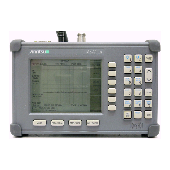
Figure 1. MS2711A Hand Held Spectrum Analyzer
1.
INTRODUCTION
This manual provides maintenance instructions for
the MS2711A Spectrum Analyzer. It describes the
product and provides performance verification proce-
dures, parts replacement procedures, and a replace-
able parts list.
2.
IDENTIFICATION NUMBER
All Anritsu instruments are assigned a six-digit se-
rial number, such as "101001." This number appears
on a decal affixed to the back panel of the instru-
ment. Please use this identification number during
any correspondence with Anritsu Service Centers
about this instrument.
490 JARVIS DRIVE · MORGAN HILL, CA 95037-2809
MAINTENANCE MANUAL
MS2711A
Hand Held
Spectrum Analyzer
MS2711A
MODE
FREQ / SPAN
AMPLITUDE
BW/SWEEP
3.
The MS2711A Spectrum Analyzer is a synthe-
sizer-based hand held spectrum analyzer that pro-
vides quick and accurate signal results. Measure-
ments can be easily made using the main
instrument functions: frequency, span, amplitude
and bandwidth. A simplified block diagram is pro-
vided in Figure 2.
4.
The following procedures can be used to verify the
performance of the MS2711A Spectrum Analyzer.
ESCAPE
1
2
CLEAR
TRACE
MEAS
3
4
SAVE
RECALL
SETUP
SETUP
6
5
LIMIT
MARKER
ENTER
7
8
SINGLE
SAVE
RECALL
CONT
DISPLAY
DISPLAY
9
0
+
/
-
PRINT
ON
SYS
OFF
.
DESCRIPTION
PERFORMANCE VERIFICATION
PROCEDURES
COPYRIGHT 2001-2002 ANRITSU CO.
P/N: 10580-00050
REVISION B
PRINTED: JULY 2002
Advertisement
Table of Contents

Related Manuals for Anritsu MS2711A


Summary of Contents for Anritsu MS2711A
- Page 1 DISPLAY PRINT MODE FREQ / SPAN AMPLITUDE BW/SWEEP Figure 1. MS2711A Hand Held Spectrum Analyzer INTRODUCTION DESCRIPTION This manual provides maintenance instructions for The MS2711A Spectrum Analyzer is a synthe- the MS2711A Spectrum Analyzer. It describes the sizer-based hand held spectrum analyzer that pro- product and provides performance verification proce- vides quick and accurate signal results.
- Page 2 LO-BAND 0 - 50 dB VCO4 VCO3 VCO1 VCO2 Figure 2. MS2711A Spectrum Analyzer Block Diagram Connect the external power supply 4.1. Frequency Accuracy (Anritsu part number 40-115) to the MS2711A. The following test can be used to verify the CW fre- quency accuracy of the Spectrum Analyzer.
- Page 3 EDIT 1000 Press and enter . Press the equivalent soft key to set the M1 marker frequency · Anritsu 34RSN50 50 ohm adapter or to 1000 MHz. equivalent BACK Press the soft key and the soft · Anritsu 15NNF50-1.5C RF Coaxial Cable key.
- Page 4 (Anritsu part number 40-115) to the Site dBc Hz measured dBc Master. BACK Press the soft key and the soft On the MS2711A, press and hold the key. CAPE/CLEAR ON/OFF key, then press the key to turn on the Spectrum Analyzer. EDIT 999.970...
- Page 5 –90 dBm. Equipment Required: NOTE · Anritsu 28N50-2 or SM/PL 50 ohm Ter- If a spur with an amplitude larger than –90 mination or equivalent dBm occurs, wait another full sweep and...
- Page 6 Source with options 2A, 4 and 15, or Wait until one full sweep is complete. equivalent MARKER Press the key and then the · Anritsu 34RSN50 50 ohm adapter or soft key. equivalent ON/OFF Press the soft key and then the ·...
- Page 7 MEASURE ON/OFF Press the soft key and 30 kHz 24 kHz 36 kHz read the Meas Occ BW value. The Meas 10 kHz 6.5 kHz 13.5 kHz Occ BW value should be ± 20% of the RBW. MS2711A HHSA MM...
- Page 8 DISPLAY CONT PRINT MODE FREQ / SPAN AMPLITUDE BW/SWEEP equivalent MS2711A · Anritsu 34NN50A 50 ohm adapter or equivalent Figure 3. Measurement Accuracy Setup · Anritsu 34RSN50 50 ohm adapter or equivalent 10 kHz ENTER select . Press to set the res- olution bandwidth to 10 kHz.
-
Page 9: Ref Level
–40. Press to set the reference level to –40 dBm. Set the MG3692A power level to –50 dBm as indicated on the power meter. Verify that the M1 reading is ± 2 dB maximum from the input signal. MS2711A HHSA MM... - Page 10 MARKER TO PEAK Press the soft key. Re- cord the M1 amplitude reading and ver- Equipment Required: ify it is £ –80 dBm. · Anritsu 28N50-2 or SM/PL 50 ohm Ter- FREQ/SPAN START Press the key and the mination or equivalent soft key.
-
Page 11: Enter Key
ENTER to set the video bandwidth to 10 equivalent kHz. · Anritsu 34NN50A 50 ohm adapter or Adjust the signal levels of both signal equivalent sources so that both signal peaks are at · Anritsu 34RSN50 50 ohm adapter or –20 dBm as indicated on the Spectrum... - Page 12 Verify that the power monitor reading is to the input of the 560-7N50B RF detec- now –40.0 dBm ±2 dB.. tor. Connect the RF Detector output to the RF Detector input of the MS2711A Spec- trum Analyzer. Attenuators 560-7N50B MA2418A...
-
Page 13: Battery Pack Removal And Replacement
Photos and il- lustrations used are representative and may show instruments other than the MS2711A Spectrum Analyzer. With the Spectrum Analyzer standing up- Figure 7. Removing the Battery Access Door right on a stable surface, locate the battery access door (Figure 5). -
Page 14: Battery Information
Spectrum Analyzer or in the optional battery charger (Anritsu part number: 2000-1029). · Use only Anritsu approved battery packs. · Recharge the battery only in the Spectrum Ana- lyzer or in an Anritsu approved charger. -
Page 15: Front Panel Assembly Removal And Replacement
Carefully depress the latch tab and discon- Figure 13. Corner Bumper Detail nect the LCD display cable from J12 on the main PCB. Carefully disconnect the keypad interface ca- ble from J1 on the main PCB. MS2711A HHSA MM... -
Page 16: Lcd Assembly Replacement
Remove the rubber cushion pad from the LCD assembly and remove the assembly. Reverse the above steps to install the re- placement assembly. Take care to position Reverse the above steps to install the re- the speaker and speaker cable properly. placement assembly. MS2711A HHSA MM... -
Page 17: Key Pad Membrane Replacement
Spectrum the main PCB. Analyzer case. Make sure the panel is cor- rectly aligned with the grooves before reas- Disconnect the semi-rigid coaxial cable from sembling the two halves together. the RF connector on the connector panel. MS2711A HHSA MM... -
Page 18: Replaceable Parts
12. REPLACEABLE PARTS Replaceable parts for the Model MS2711A Spectrum Analyzer are listed below. Table 3. Replaceable Parts List Part Number Description Part Number Description Accessories Hardware 900-861 Pan Head Screw, 4-20, 0.365 User's Guide, MS2711A 10580-00048 Spectrum Analyzer 900-869 Screw, 4-40, 0.875... - Page 19 Table 4. Anritsu Service Centers UNITED STATES FRANCE JAPAN ANRITSU COMPANY ANRITSU S.A ANRITSU CORPORATION 685 Jarvis Drive 9 Avenue du Quebec 1800 Onna Atsugi-shi Morgan Hill, CA 95037-2809 Zone de Courtaboeuf Kanagawa-Prf. 243 Japan Telephone: (408) 776-8300 91951 Les Ulis Cedex...
Need help?
Do you have a question about the MS2711A and is the answer not in the manual?
Questions and answers