Table of Contents

Related Manuals for Anritsu MS2711A


Summary of Contents for Anritsu MS2711A
- Page 1 ® Advanced Test Equipment Rentals www.atecorp.com 800-404-ATEC (2832) MS2711A Hand Held Spectrum Analyzer User's Guide Hand-Held Spectrum Analyzer for Measuring, Monitoring and Analyzing Signal Environments color cover part #: 00986-00040...
- Page 2 WARRANTY The Anritsu product(s) listed on the title page is (are) warranted against defects in materials and workmanship for one year from the date of shipment. Anritsu's obligation covers repairing or replacing products which prove to be defec- tive during the warranty period. Buyers shall prepay transportation charges for equipment returned to Anritsu for warranty repairs.
-
Page 4: Table Of Contents
Annual Verification......1-6 Anritsu Service Centers ......1-6 Chapter 2 - Quick Start Guide Introduction . - Page 5 In-Band/Out-Of-Channel Measurements ....5-4 In-band Spurious Measurement with the MS2711A ... . 5-4 Required Equipment .
- Page 6 Chapter 6 - Software Tools Program Description ........6-1 Requirements .
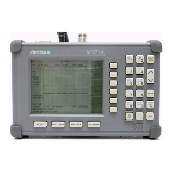
- Page 7 Chapter 1 General Information MS2711A ESCAPE CLEAR TRACE MEAS SAVE RECALL SETUP SETUP LIMIT MARKER ENTER RECALL SINGLE SAVE CONT DISPLAY DISPLAY PRINT MODE FREQ / SPAN AMPLITUDE BW/SWEEP Figure 1-1. Anritsu MS2711A Hand Held Spectrum Analyzer™ 1 - 0...
-
Page 8: Chapter 1 - General Information
10 different measurement setups. A large, high-resolution liquid crystal display (LCD) provides easy viewing in a variety of lighting conditions. The Anritsu HHSA is ca- pable of up to two and one-half hours of continuous operation from a fully charged battery and can be operated from a 12.5 Vdc source (which will also simultaneously charge the bat-... -
Page 9: Options
Chapter 1 General Information The following standard accessories are supplied with the MS2711A: · Soft Carrying Case · AC-DC Adapter · Automotive Cigarette Lighter 12 Volt DC Adapter · CD ROM containing the Software Tools program. · Serial Interface Cable (Null Modem Type) ·... - Page 10 Spare AC/DC Adapter 806-62 Spare Automotive Cigarette Lighter/12 Volt DC adapter 800-441 Spare Serial Interface Cable 760-215A Transit Case for Anritsu Hand Held Spectrum Analyzer 633-27 Rechargeable Battery, NiMH 2300-347 Anritsu Hand Held Spectrum Analyzer Software Tools 10580-00048 Anritsu HHSA User’s Guide, Model MS2711A...
-
Page 11: Performance Specifications
Chapter 1 General Information Performance Specifications Performance specifications are provided in Table 1-2. Unless otherwise noted, specified values are obtained after a five minute warmup period at a constant ambient temperature. The typical values are provided for reference, and are not guaranteed. Table 1-2. - Page 12 Chapter 1 General Information Table 1-2. Performance Specifications (2 of 2) Description Value Display Type Monochrome LCD with back light capability 640 ´ 480 Resolution Marker Modes Standard delta marker to peak marker to center Memory Trace Storage 200 traces Setup Storage 10 setups Displayed Traces...
-
Page 13: Preventive Maintenance
Anritsu HHSA preventive maintenance consists of cleaning the unit and inspecting and cleaning the RF connector on the instrument and all accessories. Clean the Anritsu HHSA with a soft, lint-free cloth dampened with water or water and a mild cleaning solution. - Page 14 Praia de Botafogo 440. Sala 2401 Luton, Bedfordshire CEP22250-040,Rio de Janeiro,RJ, LU1 3LU, England Brasil JAPAN Telephone: 015-82-43-3200 Telephone: 021-527-6922 ANRITSU CUSTOMER SERVICE LTD. FAX: 015-82-73-1303 FAX: 021-53-71-456 1800 Onna Atsugi—shi Kanagawa-Prf. 243 Japan CANADA Telephone: 0462-96-6688 FAX: 0462-25-8379 ANRITSU INSTRUMENTS LTD.
- Page 15 Chapter 2 Quick Start Guide MS2711A ESCAPE CLEAR TRACE MEAS SAVE RECALL SETUP SETUP ON/OFF Key LIMIT MARKER ENTER RECALL SINGLE SAVE CONT DISPLAY DISPLAY PRINT MODE FREQ / SPAN AMPLITUDE BW/SWEEP Figure 2-1. MS2711A Power ON/OFF Key 2 - 0...
-
Page 16: Chapter 2 - Quick Start Guide
Quick Start Guide Introduction This chapter provides a brief overview of the Anritsu MS2711A HHSA. The intent of this manual is to provide the user with a starting point for making basic measurements. For more detailed information, users may want to consult Chapter 3, Key Functions or Chapter 4, Advanced Measurement Functions. -
Page 17: Front Panel Overview
Chapter 2 Quick Start Guide Front Panel Overview The Anritsu HHSA menu-driven user interface is easy to use and requires little training. Hard keys on the front panel are used to initiate function-specific menus. There are four function hard keys located below the display, Mode, Frequency/Span, Amplitude and Band- width/Sweep. - Page 18 Chapter 2 Quick Start Guide MODE MENU SOFT KEYS SPECTRUM ANALYZER FREQ/SPAN CENTER SPAN START STOP (DEFAULT) CENTER START STOP SPAN SPAN SPAN EDIT FULL ZERO DOWN BACK 1-2-5 1-2-5 AMPLITUDE SCALE ATTEN UNITS LEVEL ATTEN AUTO MANUAL EDIT BACK UNITS dBmV dBuV...
- Page 19 Chapter 2 Quick Start Guide MODE MENU SOFT KEYS SPECTRUM A - B A + B RESET TRACE ANALYZER TRACE A->B -> -> (DEFAULT) RECALL TRACE VIEW CLEAR TRACE BACK ->B AM/FM CHANNEL FIELD MEAS STRNGTH DEMOD POWER FIELD SELECT ON/OFF BACK STRNGTH...
-
Page 20: Test Panel Connectors
Indicator light to show that the battery is being charged. The indicator light auto- Charging matically shuts off when the battery is fully charged. External Indicator light to show that the Anritsu is being powered by the external charg- Power ing unit. Headphone Allows connection of audio headphones for monitoring AM/FM demodulation. -
Page 21: Making Spectrum Analyzer Measurements
Chapter 2 Quick Start Guide Making Spectrum Analyzer Measurements Required Equipment · MS2711A Hand Held Spectrum Analyzer · Test Port Extension Cable, Anritsu 15NNF50-1.5A Procedure Step 1. Press the ON/OFF key. Step 2. Press the MODE key and use the Up/Down arrow key to select Spectrum Ana- lyzer mode. -
Page 22: Selecting The Amplitude
Chapter 2 Quick Start Guide Selecting the Amplitude Step 1. Press the AMPLITUDE key. Step 2. Press the REF LEVEL soft key and use the up/down arrow key or directly enter the desired reference level from the keypad. Press ENTER to set the amplitude level. -
Page 23: Adjusting Limits
Chapter 2 Quick Start Guide Step 4. Press the BACK soft key to return to the Markers Menu. Step 5. Repeat the steps for markers M2, M3, and M4. Adjusting Limits Step 1. Press the LIMIT key. Step 2. Enter the desired numerical value using the keypad or Up/Down arrow key. Step 3. -
Page 24: Making A Basic Measurement
Example – Measuring a 900 MHz signal Step1. Press the ON/OFF key, then the ENTER key when prompted. Step2. Connect a signal generator to the input of the Anritsu HHSA and configure it to provide a -10dBm, 900 MHz signal. -
Page 25: Set The Frequency Span
Chapter 2 Quick Start Guide Figure 2-5. Signal at 900 MHz Set the frequency span Step 1. Press the FREQ/SPAN key. Step 2. Press SPAN soft key. The Span menu is now displayed in the active function block. When activating the span function, the hand held spectrum analyzer is set to the center-fre- quency span mode. -
Page 26: Set The Amplitude
Chapter 2 Quick Start Guide Set the amplitude Generally, placing the signal peak at the reference level provides the best measurement ac- curacy. The following steps will adjust the signal peak to the reference level (Figure 2-7). Step 1. Press the AMPLITUDE key. Step 2. -
Page 27: Activate The Marker
Chapter 2 Quick Start Guide Activate the marker The marker reads both the frequency and the amplitude, and it displays these values in the message area at the bottom of the display. In this case, the marker will read 900 MHz and –10.00 dBm, as shown in Figure 2-8. -
Page 28: Save The Display
Chapter 2 Quick Start Guide Save the Display Step 1. Press the SAVE DISPLAY key. Step 2. To enter a name for the display, press the soft key letter group that contains the desired letter, then select the soft key for that letter. Continue to select letters up to a maximum of 16 characters. -
Page 29: Printing A Screen
Chapter 2 Quick Start Guide Printing a Screen Step 1. Connect the printer as shown in Figure 2-9. SEIKO PRINTER SERIAL CABLE 2000-756 HP 340 DESKJET SERIAL-TO-PARALLEL INTERFACE CABLE 2000-753 Figure 2-9. Printer Setup Step 2. Obtain the desired measurement display Step 3. -
Page 30: Determining Remaining Battery Life
Chapter 2 Quick Start Guide Determining Remaining Battery Life When the AC-DC adapter is disengaged from the Site Master, a battery indicator symbol is continuously displayed at the top-left corner of the display (Figure 2-10). A totally black bar indicates a fully charged battery. Battery Monitor Figure 2-10. -
Page 31: Symbols
Self Test At turn-on, the Anritsu HHSA runs through a series of quick checks to ensure the system is functioning properly. Note that the battery voltage and temperature are displayed in the lower left corner below the self test message. If the battery is low, or if the ambient temper- ature is not within the specified operational range, Self Test will fail. -
Page 32: Error Codes
Anritsu Service Center. NOTE: A listing of current Anritsu service centers is given in Table 1-3 , page 1-7. Range Errors A listing of Range Error messages is given in Table 2-3. -
Page 33: Using The Soft Carrying Case
Using the Soft Carrying Case The soft carrying case has been designed such that the strap can be unsnapped to allow the case to be easily oriented horizontally; thus allowing the Anritsu controls to be more easily accessed (Figure 2-12). -
Page 34: Chapter 3 - Key Functions
Key Functions Introduction This chapter provides a description of the Anritsu MS2711A Hand Held Spectrum Analyzer keypad controls. There are two kinds of keys available on the MS2711A front panel: Hard Keys and Soft Keys. Hard Keys Hard keys are those keys on the front panel that are labeled in black or blue and perform specific functions as explained below. - Page 35 ENTER Implements the current action or parameter selection. Turns the Anritsu HHSA on or off. When turned on, the system state at the last turn-off is restored. If the ESCAPE/CLEAR key is held down while the ON/OFF key is pressed, the factory preset state will be restored.
- Page 36 CONT sweep mode. The default is continuous sweep. When single sweep is selected, the Anritsu HHSA will sweep once and hold until activated. The currently selected sweep mode appears on the LCD. Single sweep mode can be used to conserve battery power.
-
Page 37: Soft Keys
Complete the entry by pressing the appropriate softkey frequency designation. CENTER Activates the center frequency function and sets the Anritsu HHSA to the center frequency. A specific center frequency can be entered by using the keypad or Up/Down arrow key. Select the GHz, MHz, kHz, or Hz softkey to accept the center frequency input. - Page 38 SCALE Activates the scale function in a 2 through 15 dB logarithmic amplitude scale. ATTEN Sets the Anritsu HHSA input attenuator so that it is either coupled auto- matically to the reference level (AUTO) or manually adjustable (MAN- UAL). UNITS Choose from the menu of amplitude related units.
- Page 39 Chapter 3 Key Functions RESET Clears the current runtime trace. A ® B Stores the current runtime trace into the Trace B buffer. A – B Performs a subtraction trace math operation. ® A + B Performs an addition trace math operation. ®...
- Page 40 Accesses a menu of Adjacent Channel Power ratio measurement options: CENTER FREQ - Activates the center frequency function and sets the Anritsu HHSA to the center frequency. A specific center frequency can be entered using the keypad or Up/Down arrow key. Select the GHz, MHz, kHz, or Hz softkey to accept the center frequency input.
- Page 41 Chapter 3 Key Functions MULTIPLE Set multiple user defined lower limits, and can be used to create a lower LOWER limit mask for quick pass/fail measurements. Menu choices are: LIMITS SEGMENT 1 SEGMENT 2 SEGMENT 3 SEGMENT 4 SEGMENT 5 BACK LIMIT Turns the audible limit beep indicator on or off.
- Page 42 Toggles the units sweep from continuous sweep mode to single sweep mode, as indicated to the left side of the display. The default is continuous sweep. When single sweep is acti- vated, the Anritsu HHSA will sweep once and hold until activated. Single sweep mode can be used to conserve battery power.
- Page 43 Chapter 3 Key Functions MINUTE The minute is displayed in the message area. Enter the desired minute (0-59) using the keypad and press ENTER to accept. MONTH The month is displayed in the message area. Enter the desired month (1-12) using the keypad and press ENTER to accept. The day as displayed in the message area.
-
Page 44: Chapter 4 - Advanced Measurement Fundamentals
HHSA. Part I will focus on advanced measurement fundamentals. Part II will focus on mea- surement techniques with examples of typical applications. Each application focuses on dif- ferent features of the Anritsu HHSA. Measurement applications and procedures covered in this section include:... - Page 45 “smeared” look to it, with the spectral lines being wider than normal and shifted to the right. (Fortunately, the Anritsu Hand Held Spectrum Analyzer has mecha- nisms designed into it that unburden the user from having to calculate the sweep rate.)
- Page 46 Connect two signal sources to the spectrum analyzer input and set the frequency of one source to 900.0 MHz and the other source to 900.030 MHz. Set both sources to the same amplitude, preferably – 20 dBm. On the MS2711A HHSA: Step 1. Set the span to 100 kHz.
- Page 47 Chapter 4 Advanced Measurement Fundamentals Example Keeping the same setup as the previous example, change the two source frequencies to 900.0 MHz and 900.020 MHz. Set both sources to the same amplitude, preferably –20 dBm. Step 1. Set the span to 100 kHz Step 2.
- Page 48 Chapter 4 Advanced Measurement Fundamentals Example Connect two signal sources to the spectrum analyzer input. Set the frequency of one source to 1900.0 MHz and the other source to 1900.100 MHz. Set one source to the + 20 dBm, and the other to –...
- Page 49 Chapter 4 Advanced Measurement Fundamentals Example Step 1. Connect a signal source to the Anritsu HHSA spectrum analyzer. Step 2. Set the input frequency to 10 MHz and the signal level to + 20 dBm. Step 3. Set the START frequency at 1 Mhz Step 4.
- Page 50 Chapter 4 Advanced Measurement Fundamentals Example 3: AM/FM Modulation Modulation is the process of translating some low frequency or baseband signal (voice, mu- sic, or data) to a higher frequency. In the modulation process, some characteristic of a car- rier signal (usually amplitude or frequency) is changed in direct proportion to the instantaneous amplitude of the baseband signal.
- Page 51 AM/FM demod- ulator. (The Anritsu HHSA comes standard with built-in AM/FM demodulator, internal speaker and headset jack).
- Page 52 Chapter 4 Advanced Measurement Fundamentals Example 5: Field Strength Measurements All antennas have losses or gain that can cause errors in measurements. The MS2711A can correct for antenna loss or gain errors using Field Strength Measurements. The antenna factors must be uploaded to the MS2711A using the Anritsu Software Tools provided with the unit.
- Page 53 The MS2711A HHSA can be used to compare frequency spectrums. Example: Step 1. Connect a signal source to the Anritsu HHSA spectrum analyzer. Step 2. Set the input frequency to 900 MHz and the signal level to –20 dBm. Step 3. Set the center frequency at 900 MHz, resolution bandwidth to 30 kHz, video bandwidth to 300 Hz, and the span to 20 MHz.
- Page 54 (1 MHz to 3000 MHz) RF detector. Mea- sured power can be displayed in dBm or Watts. Example To use the power monitor, use must first set the Anritsu HHSA to the power monitor mode and zero the power monitor. Step 1. Press the MODE key Step 2.
-
Page 55: Chapter 5 - Field Measurements
The occupied frequency bandwidth is calculated as the bandwidth containing N% of the power transmitted where N can be between 1% and 99%. Occupied Bandwidth Measurement with the MS2711A To make an occupied bandwidth measurement with the MS2711A hand held spectrum ana- lyzer, perform the steps below. Required Equipment MS2711A Hand Held Spectrum Analyzer 30 dB, 50 watt, Bi-Directional, DC –... -
Page 56: Adjacent Channel Power Leakage
Adjacent Channel Power Measurement with the MS2711A To make a channel power measurement with the MS2711A hand held spectrum analyzer, simply execute the following steps. Required Equipment MS2711A Hand Held Spectrum Analyzer 30 dB, 50 watt, Bi-Directional, DC –... -
Page 57: Out-Of-Band Spurious Emission Measurements
Measurement channel bandwidth (out of band, Figure 5-1) Allowable level of spurious emissions Out-of-band Spurious Measurement with the MS2711A To make an out-of-band spurious measurement with the MS2711A hand held spectrum ana- lyzer, simply execute the following steps. Required Equipment MS2711A Hand Held Spectrum Analyzer 30 dB, 50 watt, Bi-Directional, DC –... -
Page 58: In-Band/Out-Of-Channel Measurements
Measurement channel bandwidth Allowable level of spurious emissions In-band Spurious Measurement with the MS2711A To make an out-of-band spurious measurement with the MS2711A hand held spectrum ana- lyzer, simply execute the following steps. Required Equipment MS2711A Hand Held Spectrum Analyzer 30 dB, 50 watt, Bi-Directional, DC –... -
Page 59: Field Strength
Step 1. Use the antenna editor feature of the Software Tools to define an antenna (see page 6-5). Step 2. Upload the antenna information to the MS2711A HHSA (see page 6-5). Step 3. Press the MEAS key. Step 4. Select the FIELD STRENGTH soft key. -
Page 60: Antenna Calculations
Chapter 5 Field Measurements ANTENNA CALCULATIONS The following is a list of various antenna calculations should you find it necessary to con- vert from one to another: Conversion of signal levels from mW to mV in a 50-ohm system: where: P = power in Watts V = voltage level in Volts R = resistance in Ohms... -
Page 61: Making Power Measurements With The Power Meter
Step 6. Press the UNITS soft key to display power in Watts. Displaying Relative Power Step 7. With the desired base power level input to the Anritsu HHSA, press the REL soft key. The message area will show REL: ON and the power reading will indi- cate 100%. -
Page 62: Am/Fm Demodulation
An alternative, and possibly easier, method of examining a demodulated signal with the MS2711A is to use the built-in AM/FM demodulator and speaker or op- tional external headset. -
Page 63: Chapter 6 - Software Tools Program
(PC) running Windows 95/98/NT/2000. Requirements The Anritsu Software Tools program will run on any computer that runs Windows 95/98/NT/2000. Typically, this means having a PC with the following characteristics: ·... -
Page 64: Software Installation
Installation is similar to all other such programs. For users new to Windows, a detailed procedure is given below. Step 1. Insert the Anritsu Anritsu Software Tools CD For Windows disk into the CD drive. Step 2. Select Run under the Start menu. -
Page 65: Plot Capture
“Site Master Software Tools”. Step 6. When the installation is complete, click OK. Step 7. Double-click on the “Anritsu Software Tools ” icon to open the Software Tools program. Step 8. Click on Settings, in the top menu bar, and select Communications. Select the appropriate COM port number for the serial interface cable (null modem type). -
Page 66: Capture Multiple Traces To Pc Screen
Capture Multiple Traces from the drop-down menu. Step3. Enter the number (or numbers) of the stored-display memory location(s) (1 to 50) from which you wish to display traces in Anritsu Software Tools or select from the drop-down list. -
Page 67: Entering Antenna Factors
Step 2. Click on the “Upload” button on the tool bar (or select Upload from the Tools menu). It is important to note that the MS2711A should sweep very quickly during the data transfer, at least at 5 seconds, otherwise the Software Tools program will default to a “time-out”... -
Page 68: Saving A Plot As A Windows Metafile
Plots can be saved as Windows Metafiles (.WMF). The metafile may be imported into other graphic programs, but cannot be reloaded into the Anritsu Software Tools program. To save a plot as a Windows Metafile, click on File, in the top menu bar, and select Save as Metafile from the drop down menu. -
Page 69: Drag-N-Drop
Printing Captured traces may be printed from a PC using Anritsu Software Tools. Once a captured trace has been downloaded choose Print under the File menu for printing options. The printer setup can be altered, plots can be scaled, and multiple plots can be printed from the Print dialog box.
Need help?
Do you have a question about the MS2711A and is the answer not in the manual?
Questions and answers