Table of Contents
Advertisement
Quick Links
Advertisement
Table of Contents

Related Manuals for Elan S128P


Summary of Contents for Elan S128P
- Page 1 S128P.indd 1 1/15/2009 1:06:26 PM...
- Page 2 S128P.indd 2 1/15/2009 1:06:27 PM...
-
Page 3: Purpose Of This Manual
Purpose of This Manual This manual provides step-by-step installation instructions and connection examples, along with basic user infor- mation for installation and ongoing use of the S128P Multi-Room Controller. This manual is written for the installer of this equipment. Organization... -
Page 4: Safety Information
Protect the power cord from being walked on or pinched particularly at plugs, convenience receptacles and the point where they exit from the apparatus. Water— Do not use the apparatus near water. Page 2 © ELAN Home Systems 2009 • All rights reserved. S128P.indd 2 1/15/2009 1:06:28 PM... - Page 5 • Consult the dealer or an experienced radio/TV technician for help. CAUTION: Changes or modifications not expressly approved by Elan Home Systems could void the user’s authority to operate the equipment © ELAN Home Systems 2009 • All rights reserved.
- Page 6 S128P INSTALLATION MANUAL E L A N H O M E S Y S T E M S Page 4 © ELAN Home Systems 2009 • All rights reserved. S128P.indd 4 1/15/2009 1:06:29 PM...
-
Page 7: Table Of Contents
......................23 Stereo Zone w/ Mono Sub-Zone S128P Connections Chapter 3: SPP System Precision Panel ......................25 Connections When Using an ELAN SPP Precision Panel-Rear ..........26 ......................27 VIA! Touch Panel Connections ......................29 Olé Film Interactive Touchpads ........................29 “A”... - Page 8 S128P INSTALLATION MANUAL E L A N H O M E S Y S T E M S S128P Connections When NOT Using an ELAN SPP Precision Panel ........43 ........................43 Sense Input Connections ......................44 VIA! Touch Panel Connections ........................
- Page 9 E L A N H O M E S Y S T E M S INSTALLATION MANUAL Appendix D: Rack Mounting ......................110 Warranty ..........................Back Page © ELAN Home Systems 2009 • All rights reserved. Page 7 S128P.indd 7 1/15/2009 1:06:29 PM...
- Page 10 E L A N H O M E S Y S T E M S Items in package: • S128P Multi-Room A/V Controller • Rack Mount Brackets • Power Cord • Installation Manual Page 8 © ELAN Home Systems 2009 • All rights reserved. S128P.indd 8 1/15/2009 1:06:31 PM...
-
Page 11: Chapter 1: Introduction
The S128P is a twelve-source eight-zone preamp controller with on-board video switching. Up to four S128Ps can be linked for a total of thirty-two zones. The S128P can be controlled by IR or Serial commands, and works with ELAN VIA! ® Touch Panels, Olé™ Film Interactive Touchpads, keypads, and/or IR receivers, as well as interfacing with the VIA! ®... -
Page 12: S128P Features
• +/- 6dB Source-Leveling Optimize the input level of each source (including Local source) for smooth source switching. One dB steps for fine-tuning. Page 10 © ELAN Home Systems 2009 • All rights reserved. S128P.indd 10 1/15/2009 1:06:31 PM... - Page 13 Whole-House Music settings, etc. • Display timeout & configurable Brightness • Full ELAN Control Capability • Use with any ELAN keypad or touch panel! • IR or RS-232 Control • Uses VIA!TOOLS or ELANTOOLS setup software for all programming! • Do-Not-Disturb Temporarily disable Page, Doorbell, WHM, and Groups in any zone.
-
Page 14: System S128P Functions & Indicators
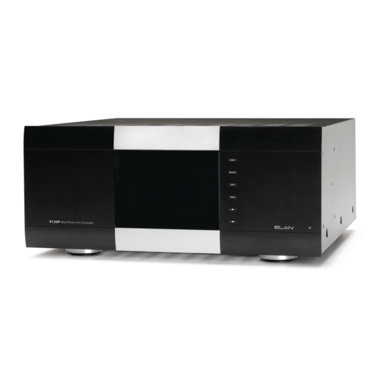
E L A N H O M E S Y S T E M S System 12 Functions & Indicators Front Panel Figure 1-1: S128P Front Panel Controls & Display Page 12 © ELAN Home Systems 2009 • All rights reserved. -
Page 15: S128P Front Panel Table
V Up (Volume Adjust) This button increases volume in selected zone V Down (Volume Adjust) This button reduces volume in selected zone Table 1-1: S128P Front Panel Controls & Display © ELAN Home Systems 2009 • All rights reserved. Page 13 S128P.indd 13... -
Page 16: Rear Panel
E L A N H O M E S Y S T E M S Rear Panel 12 13 14 15 16 17 18 22 23 Figure 1-2: S128P Rear Panel Connections Page 14 © ELAN Home Systems 2009 • All rights reserved. S128P.indd 14 1/15/2009 1:06:37 PM... - Page 17 Connect ELAN Keypads, VIA!s, Sends a 12 VDC Trigger when a or IR Receivers specific zone is active Table 1-2: S128P Rear Panel Connections © ELAN Home Systems 2009 • All rights reserved. Page 15 S128P.indd 15 1/15/2009 1:06:42 PM...
-
Page 18: Chapter 2: S128P System Design Overview Introduction
Figure 2-1: System Design Pre-Wire This section will explain the specifics of pre-wiring for an S128P system. Care should be taken at this stage to ensure a properly operational system. Most system wiring is “home-run” from the device being installed (a keypad, for example) back to the equipment location, or “head-end”. - Page 19 Use stranded, twisted pair speaker wire between amplifiers and speakers. Local Source/LSWP • Cat-5 Local Sources connect to the S128P using an LSWP Local Source Wall Plate with Cat-5 (see page 47). Remotely Located Sources • Cat-5 • RG6 or RG59 coax (if necessary) Remotely located sources connect to the S128P using an ELAN RSWP with Cat-5.
-
Page 20: Applications
E L A N H O M E S Y S T E M S Applications This section describes typical applications using the S128P in audio/video/automation installations. These are all basic in nature and should be used for guideline purposes only. Each application can be augmented as needed for individual circumstances. -
Page 21: Stereo Zones
Stereo Zones To create an independent stereo zone, simply connect the S128P’s Variable Zone Audio Outputs to a pair of ampli- fier channels. Volume will be controlled using IR or RS-232 commands at pre-amp level. Any and all speakers con- nected to these channels will ramp volume up/down together. -
Page 22: Stereo Zone W/ Fixed Sub-Zone
Volume up/down will be controlled with the volume control located in each part of the zone. If using ELAN electronic volume controls, system and source control is possible using a hand-held remote control. This application uses the least amount of amplifier channels possible. -
Page 23: Stereo Zone W/ Fixed/Variable Sub-Zone
Stereo Zone w/ Stereo Sub-Zone This application takes full advantage of the S128P’s Fixed and Variable Zone Audio Outputs. The main zone utilizes the Variable outputs. An Olé Touch Pad or VIA! Touch Panel controls source selection, source control, etc. and vol- ume up/down in the main zone. - Page 24 Model D12 REPLACE WITH SAME +12VDC OUTPUT +12V TRIGGER INPUTS TRIGGER TYPE AND RATING ONLY. VIA!NET ETHERNET Digital Power Amplifier Figure 2-6: Two Stereo Sub-Zones Page 22 © ELAN Home Systems 2009 • All rights reserved. S128P.indd 22 1/15/2009 1:06:53 PM...
-
Page 25: Stereo Zone W/ Mono Sub-Zone
LOOP OUTPUT SPEAKER INPUTS (CLASS 2 WIRING) - 40 W PER CHANNEL AT 8 OHMS TYPE FUSE Figure 2-7: Stereo Zone with Mono Sub-Zone © ELAN Home Systems 2009 • All rights reserved. Page 23 S128P.indd 23 1/15/2009 1:06:55 PM... - Page 26 Please note that an RCA ‘Y’ cable must be used from the zone’s Fixed Zone Audio Output to an Input 1 L of an ELAN D660. This cable creates a mono signal. Connect the Output 1 L of the same Channel to Input 1 R. Now, the same audio plays out of Speaker Output 1 R and Speaker Output 1 L.
-
Page 27: Chapter 3: S128P Connections
Use one or two meter RJ-45-to-RJ-45 interconnect cables for reliable connections. Six Sense Input jacks use stereo 3.5mm interconnect cables to go directly to the Sense Inputs on the S128P. The front panel also features DC power jacks for 1.5A, 4A and 10A VIA! power supplies . -
Page 28: Connections When Using An Elan Spp Precision Panel-Rear
485 are always V-Net 485, NOT Z-Net. Connect any Z-Net 485 to the RS 485 expansion block of the SPP Precision Panel to obtain proper feedback. Page 26 © ELAN Home Systems 2009 • All rights reserved. S128P.indd 26 1/15/2009 1:06:58 PM... -
Page 29: Via! Touch Panel Connections
VIA! Touch Panel Connections The S128P is designed to work flawlessly with ELAN VIA! Touch Panels. VIA! Touch Panels require ELAN 16 Volt DC power supplies. Use the PWR10 16V/10A power supply to power up to ten VIA! Touch Panels. Use the PWR4 16V/4A power supply to power up to 4 VIA! Touch Panels. - Page 30 TRIGGERS ZONE ZONE POWER ZONE ZONE of complex wiring jobs! ZONE 16VDC / 10A ZONE 16VDC / 4A 16VDC/1.5A Page 28 © ELAN Home Systems 2009 • All rights reserved. S128P.indd 28 1/15/2009 1:07:01 PM...
-
Page 31: Olé Film Interactive Touchpads
SPP for the number or Olé Touchpads and VIA! Touch Panels in the system. Figure 3-5: Olé Touchpad “A” External 16VDC Connections © ELAN Home Systems 2009 • All rights reserved. Page 29 S128P.indd 29 1/15/2009 1:07:02 PM... -
Page 32: B" Punchdown Locations-16V
SPP for the number or Olé Touchpads and VIA! Touch Panels in the system. Figure 3-6: Olé Touchpad “B” External 16VDC Connections Page 30 © ELAN Home Systems 2009 • All rights reserved. S128P.indd 30 1/15/2009 1:07:02 PM... -
Page 33: B" Punchdown Locations-12V
The SPP Precision panel has the ability to connect touchpanels, keypads and Olé Touchpads in various combinations in each zone. The “B” punchdown location can either pass 12VDC power from the S128P Controller (Internal Power) or 16VDC from a power supply connected to the front of the SPP (External). Figure 3-7 shows connectivity to the “B”... -
Page 34: C" Punchdown Locations
E L A N H O M E S Y S T E M S “C” Punchdown Locations Figure 3-8 shows connectivity to the “C” location and utilizing internal 12VDC power from the S128P Multi-Room Controller. Olé Touchpad to SPP Precision Panel (Using 12VDC from S128P) -
Page 35: C" Punchdown Locations
S128P E L A N H O M E S Y S T E M S INSTALLATION MANUAL Keypad to SPP Precision Panel (Using 12VDC from S128P) Method A Butt splice or equivalent Blue Blue Blue White/Blue W/BL White/Blue White/Blue (IR) -
Page 36: Sense Input Connections
Sense Input Connections The Sense Trigger Inputs of the S128P are primarily for use with VIA! Touch Panels and Olé Touchpads. An ELAN™SENSE Sensor can be connected that will cause VIA! Touch Panels and Olé Touchpads to execute IR or serial commands. -
Page 37: Link In/Link Out Connections
LINK IN/LINK OUT Connections Use the LINK IN and LINK OUT RJ-45 connectors to link multiple S128P chassis and multiple SPP Precision Panels. Use an RJ-45 to RJ-45 Interconnect cable from the LINK IN jack of the first SPP Panel to the LINK IN jack of the second SPP Panel and so on. -
Page 38: External Power Connections
The RS-485 information sent to these punchdowns is identical to that sent to the ZONE locations (Z#C). The RS-485 EXPANSION locations simply allow additional punchdown positions and typically WILL BE needed when installing touch panels, touchpads, and keypads in an S128P system. NOTE: The S128P Controller, generates ZNET information for status feedback. -
Page 39: Switches
ZNET/VNET Switch The ZNET-VNET switch selects between systems based on ELAN’s ZNET (S66A and S128P Multi-Room Controllers) and VNET (S86A/P ). This switch will always be in the ZNET position when installing the SPP with the S128P Controller. Figure 3-17: ZNET/VNET Switch ©... -
Page 40: Ss/Sc4-No Ss/Sc4 Switch
If the system does not contain an SS1 System Station or SC-1 Serial Controller, set the switch to the NO SS/SC4 position. Figure 3-18: SS/SC4-No SS/SC4 Switch *Note: The ELAN SC-4 is a discontinued product. Page 38 © ELAN Home Systems 2009 • All rights reserved. S128P.indd 38 1/15/2009 1:07:09 PM... -
Page 41: Connections When Using An Elan Spp Precision Panel-Front
Figure 3-20: EXT IR Connection (Not Used) Sense Input Connections Information from ELAN™SENSE Sensors connected to the S128P’s ELAN SENSE INPUTS is used to trigger events that have been programmed into VIA! Touch Panels. Typically, sensors will connect to the back of the SPP Precision Panel, then 3.5mm stereo interconnect cables will be used between the Precision Panel’s TO SENSE INPUTS jacks... -
Page 42: Ss/Sc4 Connection
E L A N H O M E S Y S T E M S SS/SC4 Connection Use the SS/SC4 RJ-45 connector to integrate an ELAN SS1 System Station or SC-4 System Controller to the S128P Multi-Room Controller in order to facilitate integration of RS-232 controlled systems such as security, lighting or HVAC. -
Page 43: Triggers Connections
There are 8 mono 3.5mm Triggers connections on the front of the SPP Precision Panel. After punching down trigger connections on the back of the SPP, use a 3.5mm mono ‘mini-to-mini’ interconnect cable to connect to the S128P Trigger Outputs as shown below. -
Page 44: Power Connections
16VDC from the connected power supply. Use an ELAN PWR1 16VDC/1.5A power supply for one VIA! Touch Panels. Use an ELAN PWR4 16VDC/4A power supply for up to four VIA! Touch Panels. Use an ELAN PWR10 16VDC/10A power supply for five-to-ten VIA! Touch Panels. It is also possible to connect up to 66 Olé Touchpads using the same 16VDC power supplies. -
Page 45: S128P Connections When Not Using An Elan Spp Precision Panel
Information from ELAN™SENSE Sensors connected to the S128P’s Sense Trigger Inputs is used to trigger events that have been programmed into VIA! Touch panels. To connect ELANSense sensors directly to the S128P, sim- ply plug the 3.5 mm stereo interconnect cable of the Sensor into the desired Sense Trigger Input. If long runs are required, the 3.5 mm stereo interconnect cable must be cut off and the cable extended using Cat-5. -
Page 46: Via! Touch Panel Connections
VIA! Touch Panel Connections If not using the SPP, it is necessary to use a PVIA Wall Plate when connecting VIA! Touch Panels to the S128P. VIA! Touch Panels require the 16V power supplies that are included with each PVIA wall plate (PVIA1, PVIA4, and PVIA10). -
Page 47: Olé Touchpad Connections
INSTALLATION MANUAL Olé Touchpad Connections ELAN Olé Touchpads require IR, RS-485+, RS-485-, 12 Volts DC, and Ground to function. Make these connections as shown below. Multiple keypads in the same zone require parallel connections. For simplicity, all eight wires can be connected straight through. -
Page 48: Local Source Connections
It is necessary to provide +12VDC for any External IR device when not using a PS128P Precision Panel. Connect only the IR and GND leads from an IR receiver, keypad, or other IR device to the EXT IR IN port on the S128P. See VIA!TOOLS or ELANTOOLS Help for information about External IR programming. -
Page 49: Vse2 Electronic Volume Control Connections
If not using a SPP or a PVSE Precision Panel, interconnects will need to be made between the electronic volume control, the S128P, the C2 Communications Controller, and the system amplifier. These connections include IR, 12VDC, Ground, and Override, as shown below. -
Page 50: C2 Communications Controller Connections
Figure 3-33: C2 to S128P Connectivity C2 to S128P Audio Connections Using a stereo RCA interconnect cable, connect C2 PAGE & DB OUT to the S128P’s PAGE IN, and one of the S128P’s MONO MOH OUT jacks to the MOH IN of the C2. -
Page 51: Source Ir Output Connections
These ports are chassis-specific and always active: any IR signal sent into S128P Chassis #1 comes out the ‘ALL’ IR outputs of Chassis #1 as shown below. When a non- ELAN multi-output source requires control from more than one chassis, an ELAN Dual Plug IR emitter should be used. -
Page 52: Unit Trigger Output Connections
Trigger Output Connections Unit Trigger Output Connections The Unit Trigger Output sends a 12VDC Trigger whenever any zone of the S128P is turned on. Use this trigger for system-wide functions such as un-muting a D660 amplifier or turning on a Z•Power Controller. -
Page 53: Audio/Video Connections
Audio Connections There are 12 Audio Source Inputs and 12 Audio Source Loop Outputs on the S128P. Each system source will be connected to a specific Source Input, allowing audio distribution to any zone of the S128P. Each Source Input cor- responds to the same numbered IR Output port. -
Page 54: Zone Outputs
Zone Outputs Variable Zone Output Connections The S128P has both Fixed and Variable Zone Audio Outputs to increase system flexibility. Variable zones are con- trolled using IR or serial commands to ramp volume up and down at preamp level. Variable Zone Audio Outputs (... -
Page 55: Fixed Output Connections
Fixed zones deliver line-level audio at full output (100% volume). Use volume controls in Fixed zones to adjust volume up and down in sub-zones. The use of ELAN impedance matching volume controls allows increased speaker loads and increased system flexibility. -
Page 56: Fixed/Variable Output Connections
Fixed and Variable Zone Output Connections The S128P has the ability to send a Fixed output and a Variable output simultaneously. This feature can be used to great advantage when utilizing sub-zones. Audio that is routed out of the Variable zone outputs will ramp volume up and down at line-level using IR or RS-232 commands. -
Page 57: Elan Rs-232 Ports
S128P and other sub-systems through RS-232 or IR. Connectivity between the SS1 and the S128P is done through two cables (included with the SS1); a 15-pin cable for IR and RS-485, and a 9-pin cable for RS-232. Connect these cables as shown below. Please consult the SS1 System Station Installation Manual for important information regarding the use of this product. -
Page 58: Pv12 Precision Video Panel
Figure 3-46: PV12 Video Precision Panel Video Switching The vast array of built-in video switching features is part of what makes the S128P so powerful! When properly configured, large video routing projects become a simple matter of “Auto-Building” IR or RS-232 commands using VIA!TOOLS or ELANTOOLS setup software. - Page 59 S128P, and requires no additional programming. By default, the first twelve video inputs of the S128P are directly tied to, or 'track' with, the twelve audio inputs. This means that the audio and composite video signals of Sources 1-12 will switch simultaneously when selected from a zone with- out any additional programming.
- Page 60 16 x 16 Mode The S128P also performs video matrix switching, meaning that any of its 16 video inputs can be routed to any of its 16 video outputs, singly or in groups. By far the most flexible option for advanced video routing, 16 x 16 mode also requires a great deal more programming.
- Page 61 Composite Composite Composite Source Source Source VIDEO AUDIO OUT VIDEO AUDIO OUT VIDEO AUDIO OUT S128P CCTV Cameras Figure 3-49: Composite Video Source Connections © ELAN Home Systems 2009 • All rights reserved. Page 59 S128P.indd 59 1/15/2009 1:07:28 PM...
- Page 62 Component Video Switching Component (Y, PB, PR) video signals can easily be switched by the S128P. Each Component video source utilizes three video inputs; one for Y, one for PB, and one for PR (Green, Blue, and Red). These inputs are grouped together through programming to switch as one entity.
- Page 63 Combination Component/Composite Video Connections Utilizing the matrix capabilities of the S128P, it is possible to switch both Component video and Composite video at the same time. Certain inputs will be assigned in groups of three to facilitate Component switching, while other inputs will remain independent and will switch according to how they are programmed.
- Page 64 (additional example / Zones 1-4 shown) Zone 4 Zone 1 Zone 2 Zone 3 VIA! VIA! S128P Figure 3-53: Default Composite Video Zone Outputs Example #2 Page 62 © ELAN Home Systems 2009 • All rights reserved. S128P.indd 62 1/15/2009 1:07:31 PM...
- Page 65 Figure 3-54: Component Video Zone Outputs Video Zone Output Connections: Composite & Component The S128P allows you to route both Composite video and Component video simultaneously. Connect the Video Zone Outputs as needed, making sure to maintain Group connections for Component video. Use VIA!TOOLS or ELANTOOLS setup software to assign outputs to specific zones as required by the system’s architecture.
- Page 66 Both Composite and Component video outputs can be looped. There are two primary applications for the Loop Outputs; sharing video sources with another system (such as a Home Theater), or multi- chassis S128P systems. The drawings below illustrate both examples. Video Loop Outputs...
-
Page 67: V8 Video Controller
V8. Connect each output of the V8 to a TV, VIA! Touch Panel, or monitor located in a zone, (see Figure 3-58). Use the ALL IR port on the S128P to control the V8 (see All IR Out Port Connections), or control it seri- ally from VIA! Touch Panels or Olé... -
Page 68: Via!®Quad Video Controller
The VIA!QUAD allows four video signals to be displayed simultaneously, sequentially, or independently. By connect- ing the output of the VIA!QUAD to a single video input of the S128P, up to four cameras can be connected while only using up one of the S128P’s Source Inputs. The video sources/cameras that are connected in this way can then be switched and displayed on any TV, VIA! Touch Panel, or monitor that is connected to the system. -
Page 69: Advanced Video Switching-Component Video
V85 Component Video Controller Use an ELAN V85 (or multiple V85s) to switch component video. Up to 8 sources can be switched to up to 32 loca- tions using multiple V85s. Connect RCA audio patch cables from a source to the S128P’s Source Audio Inputs. -
Page 70: System Expansion
UNIT 3: Zones 17-24 UNIT4: Zones 25-32 Unit ID dipswitches are found on the S128P's rear panel, and must be properly configured in order for a multi-chas- sis system to work correctly. Note: Changes to the Unit ID Dip Switches become active when the S128P is reset to Factory Default. -
Page 71: Multi-Chassis Connections
These connections are necessary when downloading your VIA!TOOLS or ELANTOOLS file from your com- puter to the S128Ps, and also if the S128P is being serially controlled, i.e. with an ELAN SS1 System Station. Each S12XK expansion comes with a 9-pin DSUB cable for this purpose. - Page 72 The S12XK also includes the single RCA interconnect cable needed to route page audio between multiple S128P’s. Connect this cable between the Page Out of S128P #1 to the Page In on S128P #2. Repeat for S128Ps 2, 3 and 4 if required.
-
Page 73: Multi-Chassis Audio/Video Connections
The Audio and Video Loop Outputs are used to route source audio and video between each S128P chassis. Each source connected to S128P Unit 1 must be routed to the corresponding source input on S128P Unit 2. This process must be repeated for each chassis. Since both the audio and video loop outputs are buffered, there will be no loss of signal between S128Ps. -
Page 74: Elan Keypad Dipswitch Settings
For detailed, step-by-step downloading instructions, see the VIA!TOOLS or ELANTOOLS Help files included with every version of VIA!TOOLS or ELANTOOLS. ELAN Keypad Dipswitch Settings When using an ELAN keypad with an S128P , the dipswitches (located on the front of each keypad) must be set to the following position: ELAN Keypad Dip Switch... -
Page 75: Chapter 5: Troubleshooting
Press DND again to cycle to the Video screen which will display programmed video information. The example screen below shows that Output 1 is assigned to Input 1 The number on the left “01” designates the S128P video output. The number on the right "01" indicates the source currently selected. The "Screen Selected" indicates that screen 1 of 2 is shown for the first set of eight video outputs. - Page 76 Press DND again to cycle to the Group screen. This will show the zones that are in each of the four possible groups associated with the S128P chassis and whether the Group is currently linked. In the example below, Group 2 is active and contains Zones 2, 3, and 7.
- Page 77 Factory Default The last screen in the Diagnostics Menu is the Factory Default screen. Use this feature to reset the S128P back to original factory programming. With the Factory Default screen visible, press ZONE and VOL UP. The unit will reset itself and all programming will be removed.
- Page 78 Check source equipment cables for damaged cables and cables. faulty connections. 4. Faulty wiring. a. Make sure any volume controls are not hooked up backwards. b. Check for shorts in wiring. Page 76 © ELAN Home Systems 2009 • All rights reserved. S128P.indd 76 1/15/2009 1:07:42 PM...
- Page 79 Correct Impedance-Match jumper settings on volume control(s) distorted in Match settings areas using incorrect. volume controls Incorrect Wiring Reversed Wiring on Volume Control, correct wiring © ELAN Home Systems 2009 • All rights reserved. Page 77 S128P.indd 77 1/15/2009 1:07:42 PM...
- Page 80 Use an RCA ‘Y’ cable with a 75 Ohm terminator connected to too high. one leg. This will reduce the source output strength. Certain satellite receivers have especially high output Page 78 © ELAN Home Systems 2009 • All rights reserved. S128P.indd 78 1/15/2009 1:07:42 PM...
- Page 81 No RS-232 source 1. Programming: missing or Verify and correct wiring and/or control. incorrect port assignment. source control commands. 2. Wiring: incorrect pin-out serial port assignment. © ELAN Home Systems 2009 • All rights reserved. Page 79 S128P.indd 79 1/15/2009 1:07:42 PM...
- Page 82 Technical Support If, after carefully following the steps in the Troubleshooting section, you are unable to resolve issues with the installation or operation of the S128P, please call ELAN Technical Support at 1-800-622-ELAN (3526). Page 80 © ELAN Home Systems 2009 • All rights reserved.
- Page 83 What an authorized installer can do In Chassis IR/RS-485 Connect Expansion Port OUT of Chassis #1 to Expansion #2-4 only; Expansion Port IN of Chassis 2, etc. using ELAN’s S12XK Expansion Kit. •WHM, Paging, ports not connected Doorbell, System Off do incorrectly not function connected.
-
Page 84: Appendix A Specifications
S128P INSTALLATION MANUAL E L A N H O M E S Y S T E M S Appendix A Specifications Table A-1 shows the equipment specifications for the S128P Multi-Room Controller. Table A-1 S128P Multi-Room Controller Specifications Item Description... - Page 85 Dimensions w/ Feet (4U w/o Feet) 17 W x 7 5/8 H x 17 D (in) 432 W x 194 H x 432 D (mm) Weight 33 lbs/14.9 kgs © ELAN Home Systems 2009 • All rights reserved. Page 83 S128P.indd 83 1/15/2009 1:07:42 PM...
-
Page 86: Appendix B: Programming
S128P. IR Commands The following list contains the IR commands for the S128P. These commands are included in the IR Library of VIA!TOOLS or ELANTOOLS. Please refer to VIA!TOOLS or ELANTOOLS Help for specific information about these There are three types of commands: •... - Page 87 • Has no effect if the zone is off. BASS DOWN • Decreases the bass in a zone. • Has no effect if the zone is off. © ELAN Home Systems 2009 • All rights reserved. Page 85 S128P.indd 85 1/15/2009 1:07:43 PM...
- Page 88 • Toggles a zone’s Doorbell from off to on to off. PAGE VOL DOWN • Decreases the Page volume in a zone. • Works if zone is on or off. Page 86 © ELAN Home Systems 2009 • All rights reserved. S128P.indd 86 1/15/2009 1:07:43 PM...
- Page 89 • Works if zone is on or off. Video Commands VIDEO1-1 • The S128P Routes Input 1 to Panel 1 in Zone. • Used with Default Tracking mode, Source-Select Tracking Mode, Un-Tracking Mode. VIDEO1-2 • The S128P Routes Input 2 to Panel 1 in Zone.
- Page 90 • Used with Default Tracking mode, Source-Select Tracking Mode, Un-Tracking Mode. COMPONENT TRACK • The S128P Routes the selected audio source’s Component video to the Component Device. • Used with Default Tracking mode, Source-Select Tracking Mode, Un-Tracking Mode. Page 88 ©...
- Page 91 16 X 16 VID IN 03 thru 16 X 16 VID IN 04 • Must use VID OUT and VID IN together. • The S128P routes a specified Input to a specified Output. • The commands must be sent Output first and then Input.
-
Page 92: Appendix C: Rs-232 Serial Control Commands
• &S12,PWR,01,1 If &S12,SYSOFF command is transmitted to the S128P, the S128P will respond with &S12,ACK. If &S12,PWR,100,1 is transmitted to the S128P, the S128P will NOT respond with a &S12,ACK because 100 is out of the scope. That field supports Zones 01-32 for this particular command. -
Page 93: Rs-232 Commands
INSTALLATION MANUAL RS-232 Commands The following list contains the RS-232 commands for the S128P. These commands are included in the IR Library of the latest versions of VIA!TOOLS or ELANTOOLS. Please refer to the VIA!TOOLS or ELANTOOLS Help file for spe- cific information about these commands and how to use them. - Page 94 • &S12,CPN,29?<cr> Queries S128P’s Component in Zone 29 for selected Component Group. • &S12,CPN,07,5<cr> S128P’s Component in Zone 7 selects Component Group 5. • &S12,CPN,02,0<cr> Notifies S128P to place S128P’s Component in Zone 2 in Tracking Mode. DND (Do Not Disturb) Description: •...
- Page 95 • &S12,DRC,13,2<cr> toggles Zone 13’s DRC from on to off or off to on. Description: • Turns specified DB off/on/toggle. This will initiate a DB that will route audio present at the S128P’s Page In audio jack to zones that have DB enabled.
- Page 96 If you send &S12,GRP,03,01<cr> and Zone 3 is not in Group 1, YOU WILL get a &S12,ACK since the command structure is correct but no grouping will occur. Page 94 © ELAN Home Systems 2009 • All rights reserved. S128P.indd 94 1/15/2009 1:07:43 PM...
- Page 97 S128P E L A N H O M E S Y S T E M S INSTALLATION MANUAL Description: These are the same commands as the S128P IR commands. Command: &S12,KEY,zz,abc<cr> Query: Reply: Parameters: <cr>: carriage return: Hexadecimal 0x0D or Decimal 13...
- Page 98 173 = 16X16 VID OUT 14 109 = VIDEO3 14 174 = 16X16 VID OUT 15 110 = VIDEO3 15 175 = 16X16 VID OUT 16 Page 96 © ELAN Home Systems 2009 • All rights reserved. S128P.indd 96 1/15/2009 1:07:43 PM...
- Page 99 • &S12,KEY,13,009<cr> turns Zone 13 Doorbell off to on or on to off. MUT (Mute) Description: • Turns specified Zone zz • Has no effect if the zone is off. Command: &S12,MUT,zz,a<cr> Query: &S12,MUT,zz?<cr> Reply: &S12,MUT,zz,a<cr> © ELAN Home Systems 2009 • All rights reserved. Page 97 S128P.indd 97 1/15/2009 1:07:43 PM...
- Page 100 • &S12,MUT,13,2<cr> toggles Zone 13’s Mute from on to off or off to on. Description: • Turns specified PG off/on/toggle. This will initiate a PG that will route audio present at the S128P’s Page In audio jack to zones that have PG enabled.
- Page 101 • &S12,SRC,02?<cr> queries Zone 2 for selected source. • &S12,SRC,09,00<cr> turns Zone 9 off SYSOFF (System Off) Description: • Turns all zones off. • Only Chassis 1 will respond. Command: &S12,SYSOFF<cr> © ELAN Home Systems 2009 • All rights reserved. Page 99 S128P.indd 99 1/15/2009 1:07:44 PM...
- Page 102 • &S12,TRE,+13,+<cr> Increments Zone 13’s treble. • &S12,TRE,02?<cr> queries Zone 2 for its treble. • &S12,TRE,13,-03<cr> sets Zone 13’s treble to -3 • &S12,TRE,13,00<cr> Zone 13 treble is flat. Page 100 © ELAN Home Systems 2009 • All rights reserved. S128P.indd 100 1/15/2009 1:07:44 PM...
- Page 103 • If zone is turned off, WHM is disabled. Command: &S12,WHM,zz,a<cr> Query: &S12,WHM,zz?<cr> Reply: &S12,WHM,zz,a<cr> Parameters: <cr>: carriage return: Hexadecimal 0x0D or Decimal 13 zz: Zone: 01-32 © ELAN Home Systems 2009 • All rights reserved. Page 101 S128P.indd 101 1/15/2009 1:07:44 PM...
- Page 104 • &S12,COR,4,BC<cr> routes Unit 4 Component Input B to Component Output C. • &S12,COR,2,DA<cr> Routes Unit 2 Component Input D to Component Output A. VID1 (Video 1) Description: Switches S128P’s Panel 1 in Zone zz to a specific Video ab. Command: &S12,VID1,zzab<cr>...
- Page 105 • &S12,VID1,29?<cr> Queries S128P’s Panel 1 in Zone 29 for selected video input. • &S12,VID1,0707<cr> S128P’s Panel 1 in Zone 7 selects Input 7. • &S12,VID1,0200<cr> Notifies S128P to place S128P’s Panel 1 in Zone 2 in Tracking Mode. VID2 (Video 2) Description: Switches S128P’s Panel 2 in Zone zz to a specific Video ab.
- Page 106 • &S12,VID3,29?<cr> Queries S128P’s Panel 3 in Zone 29 for selected video input. • &S12,VID3,0707<cr> S128P’s Panel 3 in Zone 7 selects Input 7. • &S12,VID3,0200<cr> Notifies S128P to place S128P’s Panel 3 in Zone 2 in Tracking Mode. VID4 (Video 4) Description: Switches S128P’s Panel 4 in Zone zz to a specific Video ab.
- Page 107 • &S12,VID5,29?<cr> Queries S128P’s Monitor in Zone 29 for selected video input. • &S12,VID5,0707<cr> S128P’s Monitor in Zone 7 selects Input 7. • &S12,VID5,0200<cr> Notifies S128P to place S128P’s Monitor in Zone 2 in Tracking Mode. VOR (Video Routing) Description: •...
- Page 108 • The S128P can either sense audio from the Left, Right or both Left and Right. • The S128P can detect the audio instantaneously, how ever the it can take up to 30 seconds before the S128P detects the absence of audio once the audio isremoved.
- Page 109 • &S12,LSD,1,11111100<cr> S128P Unit 1 reply. Local Audio Signals 1 thru 6 are ON and Local Audio Signal 7 and 8 are OFF. • &S12,LSD,2,00001000<cr> S128P Unit 2 reply. Local Audio Signal 5 is ON, Local Audio Signals 1, 2, 3, 4, 6, 7 and are OFF.
- Page 110 • &S12,STI,2?<cr> Queries Unit 2. • &S12,STI,1,111111<cr> S128P Unit 1 reply. All Sense Trigger Inputs are ON. • &S12,STI,2,000010<cr> S128P Unit 2 reply. Sense Trigger Input 5 ON, Sense Trigger Inputs 1, 2, 3, 4 and 6 OFF. VSD (Video Signal Detect) Description: •...
- Page 111 • &S12,VSD,1,1111110000000000<cr> S128P Unit 1 reply. Video Signals 1 thru 6 are ON and Audio Signal 7-16 are OFF. • &S12,VSD,2,0000100010000101<cr> S128P Unit 2 reply. Video Signals 5, 9, 14 and 16 are ON, Audio Signals 1, 2, 4, 6, 7, 8, 10, 11, 12, 13 and 15 are OFF.
- Page 112 Rack-Mount Brackets When mounting the S128P controller in an equipment rack, use the included Rack Mount Bracket for secure mount- ing and proper ventilation. The S128P requires four rack spaces. To install the S128P into a standard 19” equipment rack: 1.
- Page 113 3. Once the brackets are securely mounted, install the entire assembly into a standard 19” equipment rack from the front using four rack screws (not included) as shown in Figure D-3. Rack Screws Rack Screws 19" Equipment Rack Figure D-3 © ELAN Home Systems 2009 • All rights reserved. Page 111 S128P.indd 111 1/15/2009 1:07:46 PM...
- Page 114 S128P INSTALLATION MANUAL E L A N H O M E S Y S T E M S Notes: Page 112 © ELAN Home Systems 2009 • All rights reserved. S128P.indd 112 1/15/2009 1:07:46 PM...
- Page 115 S128P.indd 113 1/15/2009 1:07:46 PM...
- Page 116 Except as may be expressly provided and authorized in writing by ELAN, ELAN shall not be subject to any other obligations or liabilities whatsoever with respect to equipment manufactured by ELAN or services rendered by ELAN.
- Page 117 MATERIAL: COVER-190 G C1S / TEXT-95 G C2S SCALE: 1-1 SIZE: 17.000 X 11.000, TOL: +/- .040 FOLDING: PERFECT BINDING FINISHED SIZE: 8.500 X 11.000 PAGES: 116 NOTE: ARTWORK CREATED BY ELAN HOME SYSTEMS THIS MANUAL MUST BE RoHS COMPLIANT S128P.indd 115 1/15/2009 1:07:47 PM...
Need help?
Do you have a question about the S128P and is the answer not in the manual?
Questions and answers