
Related Manuals for Elan System12


Summary of Contents for Elan System12
- Page 1 System12 MULTI-ROOM A/V CONTROLLER I N S T A L L A T I O N M A N U A L A N D U S E R © S G U I D E...
-
Page 3: Safety Information
—These audio products must be connected to a grounding-type alternating-current circuit on a dedicated circuit breaker. This is a safety feature. The green safety wire from the A.C. circuit must be connected. © ELAN Home Systems 2004 • All rights reserved. Page 1... - Page 4 This will prevent damage to the audio products due to lightning and power-line surges. Page 2 © ELAN Home Systems 2004 • All rights reserved.
-
Page 5: Introduction
Composite video sources like VCRs and CCTV cameras. The System12 is loaded with all the features a custom installer looks for in a high-end multi-room controller, including audio/video signal sensing and... -
Page 6: Table Of Contents
600 Communications Controller Connections 35 • ........... 35 PZ600 Precision Panel ..........36 PZ600 to S12 Connections ........37 Z600 to S12 Audio Connections ..........37 Z•600 to S12 (No PZ600) Page 4 © ELAN Home Systems 2004 • All rights reserved. - Page 7 IR Commands............... 59 RS-232 Control..............63 5. Troubleshooting .............75-80 Diagnostics Menu............75 Audio................77 Video................78 Triggers................78 IR Control..............79 RS-232 Control............. 79 Communications............80 Multi-Chassis..............80 Warranty .................Back Page © ELAN Home Systems 2004 • All rights reserved. Page 5...
-
Page 8: D1650 Companion Amplifier
16 monaural zones, or any combination of the two – with cool-blue lighting that shows the level making it the ideal amplifier for the System12, settings for each channel. Channel levels can be Runs Cool ELAN’s new 8-zone multi-room A/V controller. -
Page 9: Features
Optimize the input level of each source (including Available in 240 Volt Local source) for smooth source switching. 1 dB steps for fine-tuning. For export: Model S12240 and S12R240 Listed and CE Approved ® ® © ELAN Home Systems 2004 • All rights reserved. Page 7... -
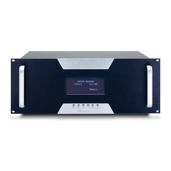
Page 10: S12 Front Panel
Press Left V button reduces volume, selected zone is in Whole- and hold DND button for Right V button increases volume House Music mode 2.5 seconds in selected zone Page 8 © ELAN Home Systems 2004 • All rights reserved. -
Page 11: Feature Definitions
Rack: ........19" (W) x 7" (H) x 15" (D) Input Impedance: ........47k Ohms 48.26cm (W) x 17.78cm (H) x 38.1cm (D) Weight:..........31 lbs/14 kgs Listed and CE Approved ® ® © ELAN Home Systems 2004 • All rights reserved. Page 9... -
Page 12: S12 Rear Panel
Connect Expansion Port Out to Connect a VIA!2 SS1 System Station Expansion Port In if using or SC4. Also for downloading multiple S12s VIA!TOOLS program files AC Power Connect to AC Power Page 10 © ELAN Home Systems 2004 • All rights reserved. -
Page 13: System Design & Applications
• RG-59 coax for base-band video only. Use coaxial cable to distribute video to TVs and IR Receivers VIA! Touch Panels throughout the house. • Cat-5 System Audio • RCA Interconnect Cables © ELAN Home Systems 2004 • All rights reserved. Page 11... -
Page 14: Applications
Zone 5 Zone 6 Zone 7 Zone 8 D1650 ZONE 1 ZONE 3 ZONE 5 ZONE 6 ZONE 7 ZONE 5 ZONE 6 ZONE 8 ZONE 2 ZONE 4 Page 12 © ELAN Home Systems 2004 • All rights reserved. -
Page 15: Stereo Zones
RS-232 commands at pre-amp level. Any and all configuration. speakers connected to these channels will ramp Zone 1 Zone 2 Zone 3 Zone 4 D1650 ZONE 3 ZONE 1 ZONE 4 ZONE 2 © ELAN Home Systems 2004 • All rights reserved. Page 13... -
Page 16: Stereo Zone W/Stereo Sub-Zone (Fixed)
Note: Fixed Zone Audio Outputs do not have DRC room. or EQ capabilities. Zone 1 D1650 ELAN Impedance-Matching Volume Controls ZONE 1 ZONE 1 Fixed Fixed Page 14 © ELAN Home Systems 2004 • All rights reserved. -
Page 17: Stereo Zone W/Stereo Sub-Zone (Fixed & Variable)
This application uses more amp channels than the previous example, but only uses one volume control in the sub-zone. Zone 1 Keypad or VIA! Volume Control D1650 ZONE 1 Variable ZONE 1 Fixed © ELAN Home Systems 2004 • All rights reserved. Page 15... -
Page 18: Stereo Zone W/Two Stereo Sub-Zones
Zone 1 D1650 ELAN Impedance-Matching Volume Controls ZONE 1 Variable ZONE 1 ZONE 1 Fixed Fixed Page 16 © ELAN Home Systems 2004 • All rights reserved. -
Page 19: Stereo Zone W/Mono Sub-Zone
IR remote control. Zone 1 Keypad or VIA! Volume Control D1650 ZONE 1 Variable ZONE 1 Fixed © ELAN Home Systems 2004 • All rights reserved. Page 17... -
Page 20: Stereo Zone W/Two Mono Sub-Zones
IR remote control if using electronic volume con- trols in the sub-zone. Zone 1 Keypad or VIA! Volume Control Volume Control D1650 ZONE 1 Variable ZONE 1 ZONE 1 (Stereo) Fixed Fixed (Mono) (Mono) Page 18 © ELAN Home Systems 2004 • All rights reserved. -
Page 21: Connections
RS232 ports, and Triggers. These various control System12 controller. Use ELAN C4545 one or two methods can be combined and integrated to create meter RJ-45-to-RJ-45 interconnect cables for reli- hundreds of possible control schemes for customized able connections every time. -
Page 22: Ps12 Precision Panel
IR G IR G IR G RED +- SS/SC4 V+ G Connect external power wires for VIA! Touch Panels NO SS/SC4 on runs longer than 110 feet V+ G V+ G Page 20 © ELAN Home Systems 2004 • All rights reserved. -
Page 23: Ps12 Rear Panel Connections
PVIA1 power supply connected WHITE/BLUE to the PVIA1 Wall Plate, or a power ORANGE WHITE/ORANGE supply connected to the PS12. GREEN WHITE/GREEN DO NOT USE BOTH POWER SUPPLIES! BROWN WHITE/BROWN CABLE © ELAN Home Systems 2004 • All rights reserved. Page 21... -
Page 24: Keypads/Ir Receivers
Butt splice or equivalent Connector Blue Blue IR Receiver White/Blue White/Blue Orange Orange 485+ White/Orange White/Orange Cat-5 485- Green Green +12 VDC +12V White/Green White/Green Brown Brown White/Brown White/Brown Page 22 © ELAN Home Systems 2004 • All rights reserved. -
Page 25: Local Source Inputs
Connector Local Audio Source Blue Back Front Brown White/Blue Audio Out Orange White/Brown Window White/Orange Cat-5 Orange Green White/Green White/Orange Brown White/Brown IR Emitter Blue (included w/ LSWP) White/Blue © ELAN Home Systems 2004 • All rights reserved. Page 23... -
Page 26: External Ir Input
IR Receiver to PS12 Rear Panel EXT IR Connector EXT IR IR Receiver +12VDC 485+ 485- +12V PS12 Note: A +12V connector or any of the KP punch-down connectors can be used to power the IR receiver. Page 24 © ELAN Home Systems 2004 • All rights reserved. -
Page 27: Electronic Volume Controls/Pvse Precision Panel
• Provides volume control in Fixed zone out areas ing of VSE IR signals to the System12 Precision (usually sub-zones) Panel (PS12). Two RJ-45 jacks on the rear of the •... -
Page 28: Sense Trigger Inputs
RCA adaptor. ELAN™SENSE Sensor to PS12 Sense Trigger Inputs PS12 SENSE 6 SENSE 5 SENSE 4 SENSE 3 SENSE 2 SENSE 1 S G V Black White AUDIO SENSOR Page 26 © ELAN Home Systems 2004 • All rights reserved. -
Page 29: Ps12 Front Panel Connections
These local sources will act as a thirteenth source, but will only be available in the zone to which they are connected. PS12 to S12 Local Source Connections (Zone 1 Shown) PS12 ZONE LOCAL ELAN C4545 © ELAN Home Systems 2004 • All rights reserved. Page 27... -
Page 30: Via! Power/Via!Net Connections
VIA!NET Connections (VIA!SC4/SS1 to PS12) VIA!NET Dip Switch Settings VIA!SC4 PS12 SS/SC4 TO VIA!NET TO VIA!NET ELAN C45P NO SS/SC4 PS12 VIA!2-SS1 (factory default) TO VIA!NET VIA!NET ELAN C45P Page 28 © ELAN Home Systems 2004 • All rights reserved. -
Page 31: Antennas/External Ir Input
3.5mm mono interconnect cable between EXT IR of the PS12 and EXT IR IN of the System12. PS12 External IR Output to S12 External IR Input EXT IR 3.5mm mono interconnect cable PS12 © ELAN Home Systems 2004 • All rights reserved. Page 29... -
Page 32: To Sense Inputs
(Sense 1 on the back of the PS12 must be connected to Sense 1 on the S12). PS12 To Sense Inputs to S12 Sense Trigger Inputs (Sense Triggers 1-3 shown) TO SENSE INPUTS USE STEREO 3.5mm PLUGS ONLY Page 30 © ELAN Home Systems 2004 • All rights reserved. -
Page 33: S12 Connections When Not Using A Ps12 Precision Panel
Green 485- Z485- C45P White/Blue ELAN Brown Blue ST/SNS C45P VIA1 XLINK Standard ELAN RJ-45 Pin-Out PIN # COLOR CODE BLUE WHITE/BLUE ORANGE WHITE/ORANGE GREEN WHITE/GREEN BROWN WHITE/BROWN CABLE © ELAN Home Systems 2004 • All rights reserved. Page 31... -
Page 34: Keypads/Sense Trigger Inputs
3.5 mm stereo interconnect cable of gramming Sense Triggers. the Sensor into the desired Sense Trigger Input. ELAN™SENSE Sensor to S12 Sense Trigger Inputs AUDIO SENSOR Page 32 © ELAN Home Systems 2004 • All rights reserved. -
Page 35: Local Source/External Ir Connections
IR device to the EXT IR IN port on the S12. See VIA!TOOLS Help for information about External IR programming. External IR Receiver to S12 External IR Input IR Receiver +12VDC Sleeve © ELAN Home Systems 2004 • All rights reserved. Page 33... -
Page 36: Electronic Volume Control Connections
ZONE LOCAL time and make sense out ZONE LOCAL ZONE LOCAL ZONE LOCAL ZONE LOCAL VIA!POWER ZONE LOCAL of complex wiring jobs! 16VDC / 10A 16VDC / 4A VIA!NET Page 34 © ELAN Home Systems 2004 • All rights reserved. -
Page 37: Z•600 Communications Controller Connections
DB1 and DB2 functions for the S12. Front Rear N.O. W/Bl N.O. W/Or N.O. W/Gr N.O. W/Br RELAY TELCO PHONE W/Bl TELCO W/Or W/Gr W/Br OVERRIDE OVERRIDE © ELAN Home Systems 2004 • All rights reserved. Page 35... -
Page 38: Pz600 To S12 Connections
3.5mm stereo interconnect cable from the PAGE/DB OUT of the PZ600 to the PAGE TRIGGER IN of the S12. PZ600 to S12 Doorbell Connections (Single Page/DB Trigger) PAGE/DB 3.5mm stereo interconnect cable PZ600 Page 36 © ELAN Home Systems 2004 • All rights reserved. -
Page 39: Z600 To S12 Audio Connections
(for multi-chassis systems - see System Expansion p. 54) Z•600 to S12 (No PZ600 Precision Panel) Z•600 Stereo C45P RCA Cable Tip = Blue Sleeve = Green 3.5mm mono interconnect cable © ELAN Home Systems 2004 • All rights reserved. Page 37... -
Page 40: Additional S12 Connections
A/V Receiver Non-ELAN Multi-Output Source ELAN dual-jack IR mini-emitter S12 #2 Note: When using more than 2 Chassis, multiple ELAN dual-jack IR mini-emitters must be used for multi-output non-ELAN sources! Page 38 © ELAN Home Systems 2004 • All rights reserved. -
Page 41: Trigger Output Connections
D1200 or D1650 amplifier. S12 Zone Trigger Outputs to D1650 Zone Trigger Inputs (Zones 1 & 8 Shown) D1650 3.5mm mono interconnect cable 3.5 mm mono interconnect cable © ELAN Home Systems 2004 • All rights reserved. Page 39... -
Page 42: Audio Connections
Loop Output to a Home Theater receiver or an additional S12 chassis. Audio Loop Connections Source 1 Shown TUNER DVD PLAYER SATELLITE RECEIVER AUDIO OUT VIDEO AUDIO OUT AUDIO OUT VIDEO A/V Receiver Audio Input Page 40 © ELAN Home Systems 2004 • All rights reserved. -
Page 43: Zone Output Connections/Variable
Variable zones are controlled using IR or serial commands to ramp volume up and down at preamp level. Variable Zone Audio Outputs ( Zones 1-4 Shown) D1650 ZONE 1 ZONE 3 ZONE 4 ZONE 2 © ELAN Home Systems 2004 • All rights reserved. Page 41... -
Page 44: Zone Output Connections/Fixed
Fixed Zone Audio Outputs utilize none of these functions, therefore zones and sub-zones may sound different from each other. Fixed Zone Audio Outputs ( Zones 1-4 Shown) D1650 ELAN Impedance-Matching Volume Controls ZONE 1 ZONE 1 Fixed Fixed Page 42 © ELAN Home Systems 2004 • All rights reserved. -
Page 45: Zone Output Connections/Fixed & Variable
IR or RS-232 commands. Audio that is routed out the Fixed outputs will be adjusted using volume controls. Fixed/Variable Zone Audio Outputs (Zone 1 Shown) D1650 ZONE 1 Variable ZONE 1 Fixed © ELAN Home Systems 2004 • All rights reserved. Page 43... -
Page 46: Via!2
SC4 to S12 Connections ® When controlling a System12 with ELAN’s VIA!SC4 System Controller, use the 6-Pin DIN-to-9-Pin serial cable and the male-to-male DB9 gender-changer that is included with the SC4. Plug the 6-Pin DIN (round) connector into the SC4’s ELAN RS-232 OUT port. -
Page 47: Pv8 Video Precision Panel
Composite, Component and High Video Source Input Table Video Output Table Available Available Available Available Composite Video Component Video Composite Video Component Video Outputs Outputs Source Inputs Source Inputs © ELAN Home Systems 2004 • All rights reserved. Page 45... -
Page 48: Default Tracking Mode
Zone 6 Zone 7 Zone 8 VIA! TV VIA! TV VIA! TV VIA! TV VIA! TV VIA! TV VIA! TV VIA! TV Composite Video Inputs Composite 13-15 Video Input Page 46 © ELAN Home Systems 2004 • All rights reserved. -
Page 49: Source-Select Tracking Mode
Essentially, a button on a VIA! Touch Panel or a keypad will be programmed with a specific input-select command(s) and output-select command(s). Specific instructions on S12 video programming are provided with VIA! TOOLS setup software (revision 5.0 or higher). © ELAN Home Systems 2004 • All rights reserved. Page 47... -
Page 50: Composite Video Source Connections
RG-6 or RG-59 coax with F-to-RCA adaptors. Composite Video Source Connections Composite Composite Composite Source Source Source VIDEO VIDEO AUDIO OUT VIDEO AUDIO OUT AUDIO OUT CCTV Cameras Page 48 © ELAN Home Systems 2004 • All rights reserved. -
Page 51: Component Video Switching
(inputs 4, 5, 6) COMPONENT VIDEO OUTPUTS COMPONENT VIDEO OUTPUTS COMPONENT VIDEO OUTPUTS COMPONENT VIDEO OUTPUTS COMPONENT VIDEO OUTPUTS 1st Component video source to Component video input ‘A’ (inputs 13, 14, 15) © ELAN Home Systems 2004 • All rights reserved. Page 49... -
Page 52: Composite/Component Video Switching
Tools setup software for information about S12 video programming. ® Component/Composite Video Source Connections COMPONENT VIDEO OUTPUTS COMPOSITE VIDEO OUTPUT COMPONENT VIDEO OUTPUTS COMPOSITE VIDEO OUTPUT COMPONENT VIDEO OUTPUTS Page 50 © ELAN Home Systems 2004 • All rights reserved. -
Page 53: Video Output Connections
TV/monitor, therefore both Zone Video Outputs may not always be used. Composite Video Zone Outputs (additional example / Zones 1-4 shown) Zone 3 Zone 4 Zone 1 Zone 2 VIA! VIA! © ELAN Home Systems 2004 • All rights reserved. Page 51... -
Page 54: Component Video Zone Outputs
See VIA!Tools for detailed programming instructions. Composite/Component Video Zone Outputs Zone 1 Zone 3 Zone 2 VIA! VIA! VIA! Zone 5 Zone 7 Page 52 © ELAN Home Systems 2004 • All rights reserved. -
Page 55: Video Loop Outputs
Component Composite Source Source Video Video A/V Receiver A/V Receiver Component Input Composite Input Video Loop Outputs (Multiple S12 Chassis) Component Composite Source Source Video S12 #1 S12 #2 © ELAN Home Systems 2004 • All rights reserved. Page 53... -
Page 56: System Expansion
Factory Default. Each chassis (Zones 9-16) must be reset in order for changes to take effect. See pg. 60 for Factory Default procedure. S12 #3 (Zones 17-24) S12 #4 (Zones 25-32) Page 54 © ELAN Home Systems 2004 • All rights reserved. -
Page 57: Multi-Chassis Connections
S12 #2 (Zones 9-16) to S12 #3 (Zones 17-24) to S12 #3 (Zones 17-24) to S12 #4 (Zones 25-32) to S12 #4 (Zones 25-32) © ELAN Home Systems 2004 • All rights reserved. Page 55... -
Page 58: Communications Connections
Page In on S12 #2. Repeat for S12s 2, 3 and 4 if required. Note: Do not link MOH connections. Multi-Chassis Communications Connections S12 #1 mono stereo 3.5mm interconnect cable RCA Cable S12 #2 To S12 #3 To S12 #4 Page 56 © ELAN Home Systems 2004 • All rights reserved. -
Page 59: Audio/Video Connections
(Audio Source 1, Audio/Composite Source 2, and Component Video Source D Shown) S12 #1 (Zones 1-8) From Source VIDEO AUDIO L AUDIO R S12 #2 (Zones 9-16) to S12 #3 (Zones 17-24) to S12 #4 (Zones 25-32) © ELAN Home Systems 2004 • All rights reserved. Page 57... -
Page 60: Programming
I/O PC card for use with VIA!TOOLS: Socket Communications, Inc. Serial I/O PC Card, Product #: SL0700-004. For further information on this product, go to http://www.socketcom.com/product/SL0700-004.asp. Page 58 © ELAN Home Systems 2004 • All rights reserved. -
Page 61: Ir Commands
• Toggles a zone's Whole House Music from off to on VOLUME UP to off. • Increases the volume in a zone. • Has no effect if the zone is off. © ELAN Home Systems 2004 • All rights reserved. Page 59... - Page 62 • The S12 Routes Input 8 to Panel 1 in Zone. • Decreases the Page volume in a zone. • Used with Default Tracking mode, Source-Select • Works if zone is on or off. Tracking Mode, Un-Tracking Mode. Page 60 © ELAN Home Systems 2004 • All rights reserved.
- Page 63 Zone. Component video to the Component Device. • Used with Default Tracking mode, Source-Select • Used with Default Tracking mode, Source-Select Tracking Mode, Un-Tracking Mode. Tracking Mode, Un-Tracking Mode. © ELAN Home Systems 2004 • All rights reserved. Page 61...
- Page 64 EXTIR ON 1 thru EXTIR ON 12 • Same as EXTIR OFF 1 except they turn ON their respective ports. EXTIR ALLON • Turns ALL Source IR Emitter Outputs ON. Page 62 © ELAN Home Systems 2004 • All rights reserved.
-
Page 65: Rs-232 Control
NOT respond with a &S12,ACK because 100 is out is received prior to 50ms, another command can be of the scope. That field supports Zones 01-32 for this transmitted immediately. particular command. © ELAN Home Systems 2004 • All rights reserved. Page 63... -
Page 66: System Commands
• &S12,BAS,+13,+<cr> Increments Zone 13's bass. • &S12,BAS,02?<cr> queries Zone 2 for its bass. • &S12,BAS,13,-03<cr> sets Zone 13's bass to -3. • &S12,BAS,13,00<cr> Zone 13 bass is flat Page 64 © ELAN Home Systems 2004 • All rights reserved. - Page 67 • &S12,DRC,02?<cr> queries Zone 2's DRC. • &S12,DRC,13,1<cr> turns Zone 13's DRC on. Reply: • &S12,DRC,13,2<cr> toggles Zone 13's DRC from &S12,GRP,zz,gg,a<cr> on to off or off to on. © ELAN Home Systems 2004 • All rights reserved. Page 65...
- Page 68 069 = VIDEO1 6 070 = VIDEO1 7 Zone: 01-32 071 = VIDEO1 8 072 = VIDEO1 9 073 = VIDEO1 10 074 = VIDEO1 11 075 = VIDEO1 12 Page 66 © ELAN Home Systems 2004 • All rights reserved.
- Page 69 125 = VIDEO4 14 126 = VIDEO4 15 189 = 16X16 VID IN 14 127 = VIDEO4 16 190 = 16X16 VID IN 15 191 = 16X16 VID IN 16 © ELAN Home Systems 2004 • All rights reserved. Page 67...
- Page 70 0 = OFF • &S12,MUT,13,1<cr> turns Zone 13's Mute on. 1 = ON • &S12,MUT,13,2<cr> toggles Zone 13's Mute from 2 = TOG on to off or off to on. Page 68 © ELAN Home Systems 2004 • All rights reserved.
- Page 71 • &S12,TRE,+13,+<cr> Increments Zone 13's treble. Query: • &S12,TRE,02?<cr> queries Zone 2 for its treble. &S12,SYSOFF?<cr> • &S12,TRE,13,-03<cr> sets Zone 13's treble to -3 • &S12,TRE,13,00<cr> Zone 13 treble is flat. Reply: &S12,SYSOFF,a<cr> © ELAN Home Systems 2004 • All rights reserved. Page 69...
- Page 72 Input A to Component Output E. Reply: • &S12,COR,4,BC<cr> routes Unit 4 Component &S12,WHM,zz,a<cr> Input B to Component Output C. • &S12,COR,2,DA<cr> Routes Unit 2 Component Input D to Component Output A. Page 70 © ELAN Home Systems 2004 • All rights reserved.
- Page 73 Input 7. • &S12,VID3,02,00<cr> Notifies S12 to place S12's Reply: Panel 3 in Zone 2 in Tracking Mode. &S12,VID2,zz,ab<cr> Parameters: <cr>: carriage return: Hexadecimal 0x0D or Decimal 13 Zone: 01-32 © ELAN Home Systems 2004 • All rights reserved. Page 71...
- Page 74 • &S12,VOR,4,13,16<cr> routes Unit 4 Input 16 to &S12,VID5,zz,ab<cr> Output 13. • &S12,VOR,2,13,12<cr> routes Unit 2 Input 12 to Parameters: Output 13. <cr>: carriage return: Hexadecimal 0x0D or Decimal 13 Zone: 01-32 Page 72 © ELAN Home Systems 2004 • All rights reserved.
- Page 75 30 seconds before the S12 detects the absence of audio once the audio is Query: removed. &S12,PGD,u?<cr> • Works if System/Zone is off or on. © ELAN Home Systems 2004 • All rights reserved. Page 73...
- Page 76 • &S12,STI,1,111111<cr> S12 Unit 1 reply. All Sense Trigger Inputs are ON. • &S12,STI,2,000010<cr> S12 Unit 2 reply. Sense Trigger Input 5 ON, Sense Trigger Inputs 1, 2, 3, 4 and 6 OFF. Page 74 © ELAN Home Systems 2004 • All rights reserved.
-
Page 77: Troubleshooting
Currently Output Video Feeds Selected Jack 16 Note: This display is only valid for Default Tracking Mode and Source-Select Tracking Mode. It is invalid for 16 X 16 Mode. © ELAN Home Systems 2004 • All rights reserved. Page 75... -
Page 78: Factory Default
C u r r e n t s e t t i n g s ! ! ! w i l l l o s t ! ! ! Page 76 © ELAN Home Systems 2004 • All rights reserved. -
Page 79: Audio
No volume control amp in variable zone. amplifier. with IR zone controller (Keypad, 2. Loop output connected instead Connect variable zone output to etc.). of variable zone output. amplifier. © ELAN Home Systems 2004 • All rights reserved. Page 77... -
Page 80: Video
Triggered event fails to occur. b. See Diagnostics Menu p. 59. c. Test for Voltage w/ digital multi-meter. Example: Volume Control Correct reading is 12 VDC. Override does not function. Page 78 © ELAN Home Systems 2004 • All rights reserved. -
Page 81: Ir Control
No RS-232 source control. 1. Programming: missing or incor- Verify and correct programming. rect source control commands. 2. Wiring: incorrect pin-out or Verify and correct wiring and/or serial port assignment. port assignment. © ELAN Home Systems 2004 • All rights reserved. Page 79... -
Page 82: Communications
Expansion Kit. Technical Support If, after carefully following the steps in the Troubleshooting section, you are unable to resolve issues with the installation or operation of the System12, please call ELAN Technical Support at 1-800-622-ELAN (3526). Page 80 © ELAN Home Systems 2004 • All rights reserved. - Page 83 SYSTEM12 E L A N H O M E S Y S T E M S INSTALLATION MANUAL Notes: © ELAN Home Systems 2004 • All rights reserved. Page 81...
-
Page 84: Limited Warranty
Limited Warranty ELAN HOME SYSTEMS L.L.C. ("ELAN") warrants the System12 to be free from defects in materials and workmanship for the period of two years (2 years) from date of purchase. If within the applicable warranty period above purchaser discovers that such item was not as warranted above and promptly notifies ELAN in writing, ELAN shall repair or replace the item at the company's option.
Need help?
Do you have a question about the System12 and is the answer not in the manual?
Questions and answers