Table of Contents
Advertisement
Quick Links
Advertisement
Table of Contents

Related Manuals for Elan SC-1


Summary of Contents for Elan SC-1
- Page 3 ELAN HOME SYSTEMS SC-1 INSTALLATION MANUAL Items in Box • SC-1 • RJ-45 to DB9 Adapter • Installation Manual • RJ-45 to RJ45 Cable © ELAN Home Systems 2008 • All rights reserved Page 1...
-
Page 4: Table Of Contents
Operations ................... 22 Troubleshooting ................24 Appendix A: Specifications ............25 Appendix B: Programming ............26 Appendix C: RJ-45 to DB9 Wiring Code ........ 27 Warranty ................. Back Page Page 2 © ELAN Home Systems 2008 • All rights reserved. -
Page 5: Introduction
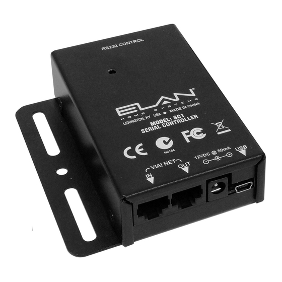
ELAN HOME SYSTEMS SC-1 INSTALLATION MANUAL Introduction The SC-1 has one Serial Port for the integration of local and system RS-232-controlled sub-systems and components (i.e. lighting, temperature, security), allowing wired VIA! Touch Panels, Wireless Color Touch Panels, and Olé Touchpads to control these systems. - Page 6 ELAN HOME SYSTEMS SC-1 INSTALLATION MANUAL Functions & Indicators Figure 1-1: Functions & Indicators Page 4 © ELAN Home Systems 2008 • All rights reserved.
- Page 7 Connection VIA!NET RS485 Data Connection Loop VIA!NET RS485 Data Input Connection Table 1-1: Functions & Indicators See Appendix C for wiring details RJ-45 (EIA 561) to Male DB9 (DTE) © ELAN Home Systems 2008 • All rights reserved Page 5...
-
Page 8: System Design
Applications The SC-1 is extremely versatile. Whether being located in the ‘head- end’ of a central equipment rack or remotely located in the Zone or a combination of both, the SC-1 makes adding a serial controlled devices easy. - Page 9 The S86A/S86P Multi-Room Controller uses a VIA!NET data buss to transmit V485 information. A basic S86A/P can take advantage of the KP 1-6 connector for a direct link to the SC-1 when an SPP Precision Panel is not used. Direct connection of an Olé Touch Pad to the SC-1 streamlines the wiring network when installing a single SC-1 to an S86P as shown in applications Figure 2-2.
- Page 10 16VDC / 10A 16VDC / 4A Cat-5 16VDC/1.5A 16 VDC/ PWR4 Zone Jandy RJ-45 Wall Plate RJ-45 RS Serial Adapter RS-232 SC-1 Connector Figure 2-1: S6 Jandy Pool Application Page 8 © ELAN Home Systems 2008 • All rights reserved.
- Page 11 ZONE 3 Olé RJ-45 RS-232 Connectors LSWP Zone Local Source RJ-45 Wall Plate Wall Plate VIDEO Cat-5 3.5mm IR Cable VIA!migo A/V Cables Figure 2-2: S86P Application (No SPP) © ELAN Home Systems 2008 • All rights reserved Page 9...
- Page 12 16 VDC/ PWR3 PWR4 RJ-45 RS-232 SC-1 Connectors LSWP Zone Local Source RJ-45 Wall Plate Wall Plate VIDEO Cat-5 3.5mm IR Cable VIA!migo A/V Cables Figure 2-3: S12 VIAmigo Application Page 10 © ELAN Home Systems 2008 • All rights reserved.
- Page 13 VIA-NET COM 2 HOST COM 3 LINK ELAN COM 4 RX/TX Components SC-1 HVAC Panel RJ-45 RS-232 Connector Security Panel RJ-45 SC-1 RS-232 Connector Figure 2-4: SC-1 Loop Application © ELAN Home Systems 2008 • All rights reserved Page 11...
- Page 14 Components SC-1 PWR3 SC-1 Zone RJ-45 RJ-45 Wall Plates RS-232 Connectors LSWP Local Source Wall Plate VIDEO Cat-5 3.5mm IR Cable VIA!migo A/V Cables Figure 2-5: S86P Application (w/SPP) Page 12 © ELAN Home Systems 2008 • All rights reserved.
-
Page 15: Connections
This chapter describes all necessary connections for installing the SC-1. VIA!NET When adding an SC-1 to expand Com Port capability use a Cat-5 wire with ELAN Standard RJ-45 pinout to connect the SC-1 to a system’s VIA!NET when installing ELAN devices including SS1s. Set the SPP SS/SC4 switch to the up position (ON). - Page 16 30 wired VIA! Touch Panels, wireless VIA!2 Touch Panels (with their companion Zone SS1s) and/or Olé Touchpads. • The maximum distance between an SC-1 and any one wired VIA! Touch Panel and companion Zone SS1 or Olé Touchpad CANNOT EXCEED 1000 feet.
- Page 17 Keep in mind the following points: • Use VIA!NET Repeaters when the TOTAL combined wire length to all VIA! Touch Panels or SC-1 VIA!NET Ports exceeds the 2000 ft. maximum limit. NOTE: Wire runs WITH VIA!NET Repeaters still must not exceed 1000ft.
- Page 18 ELAN HOME SYSTEMS SC-1 INSTALLATION MANUAL VIA!Net Repeater Figure 3-2: VIA!NET Repeater All Cat-5 connections described in this manual will use ELAN’s standard pinout configuration, as shown below. Blue (Pin 1) - System Sense (Passthrough) White/Blue (Pin 2) - IR Out (Passthrough)
- Page 19 SC-1 INSTALLATION MANUAL SPP/VNET When locating an SC-1 in a Zone, i.e. to control a TV or VIAmigo, use a Cat-5 wire with ELAN Standard RJ-45 pinout to connect the SC-1 to an SPP ZONE VIA 16V punchdown when installing the SC- 1.
- Page 20 When a Zone application is necessary for S6/S12 Multi-Room controllers, use a Cat-5 wire with ELAN Standard RJ-45 pinout to connect the SC-1 to an SPP ZONE VIA 16V punchdown and the RS485 expansion block. Connect the IR, V485+/-, GND, and +16V to the ZONE VIA Punchdown and the Z485+/- to the RS485 Expansion block when installing the SC-1.
- Page 21 SC-1 INSTALLATION MANUAL SC-1 Power If the SC-1 is connected using the SS/SC4 Port of the SPP Preci- sion Panel it will be necessary to provide an external power supply. Connect the PWR3 12VDC power supply (not included) to the SC-1 POWER port after all connections are made.
- Page 22 Downloads are facilitated through the USB Download port. See Appendix B for more details. Note: A Standard USB-A to USB-Mini-B cable must be utilized for programming and is not included with the SC-1. Figure 3-7: USB Programming Port Page 20...
- Page 23 Lighting, HVAC, and Security systems. Connect one end of an RJ-45 to RJ-45 CAT5 cable into the included DB-9 to RJ-45 connec- tor, and the other end into the SC-1’s RJ-45 232 Port. Connect the DB-9 connector to the serial device. See Appendix C for RJ-45 to...
-
Page 24: Operations
ELAN HOME SYSTEMS SC-1 INSTALLATION MANUAL Operation Diagnostics The SC-1 LED Indicator is an excellent source of information. It provides visual feedback determining operational status. Figure 4-1: LED Indicator Slow Blink Normal operations. Unit will blink in response to commands. - Page 25 USB connection. 3 blinks, long pause Slow Blink Interrupted download, corrupted download, One blink, or incompatible firmware. Download firmware short pause, update through USB connection. 2 blinks, long pause © ELAN Home Systems 2008 • All rights reserved Page 23...
-
Page 26: Troubleshooting
1. Programming: Verify and correct device missing or incor- programming. control. rect device control commands. 2. Wiring: incorrect Verify and correct pin-out or serial wiring and/or port assignment. port assignment. Page 24 © ELAN Home Systems 2008 • All rights reserved. -
Page 27: Appendix A: Specifications
RJ-45 to RJ-45 (Not Included) Dimensions 3”L x 2.3”W x 1”H 7.62cm L x 5.842cm W x 2.54cm H Weight .5 lbs. 227 grams Shipping Weight 1 lbs. 454 grams © ELAN Home Systems 2008 • All rights reserved Page 25... -
Page 28: Appendix B: Programming
ELAN HOME SYSTEMS SC-1 INSTALLATION MANUAL Appendix B: Programming The SC-1 must be programmed with ELAN VIA!TOOLS or ELANTOOLS Setup Software. SC-1 Standard USB-A to USB-Mini-B Cable Figure B-1: Programming Connectivity Connect a PC running Windows XP or Vista using a... -
Page 29: Appendix C: Rj-45 To Db9 Wiring Code
Data Brown Brown Clear To Send White BR/WH Request To Send Table C-1: RJ-45 (T561A) to Male DB9 Wire Code Note: * No connection to SC1 from DCD pin. © ELAN Home Systems 2008 • All rights reserved Page 27... - Page 30 ELAN HOME SYSTEMS SC-1 INSTALLATION MANUAL Notes: Page 28 © ELAN Home Systems 2008 • All rights reserved.
-
Page 32: Warranty
(2 years) from date of purchase. If within the applicable warranty period above purchaser discovers that such item was not as warranted above and promptly notifies ELAN in writing, ELAN shall repair or replace the item at the company's option. This warranty shall not apply (a) to equipment not...
Need help?
Do you have a question about the SC-1 and is the answer not in the manual?
Questions and answers