Table of Contents
Advertisement
Operating Instructions
DULCOMETER
Part 1:
Mounting and installation instructions for wall-mounted and
control panel-mounted devices
Typ/type D
___ ___ ___ ___ ___ ___ ___ ___ ___ ___ ___ ___ ___
D1C A
T. Nr./P. No.: 987725
®
D1C
DED1C1S001
Identcode
ProMinent Dosiertechnik GmbH · 69123 Heidelberg · Germany
G/GB/F/E
Typ/type W
BA DM 123 04/03 G/GB/F/E
DED1C1W001
Advertisement
Table of Contents

Subscribe to Our Youtube Channel
Related Manuals for ProMinent DULCOMETER D1CA


Summary of Contents for ProMinent DULCOMETER D1CA
- Page 1 G/GB/F/E Typ/type D Typ/type W DED1C1S001 DED1C1W001 ___ ___ ___ ___ ___ ___ ___ ___ ___ ___ ___ ___ ___ D1C A Identcode T. Nr./P. No.: 987725 ProMinent Dosiertechnik GmbH · 69123 Heidelberg · Germany BA DM 123 04/03 G/GB/F/E...
- Page 2 Betriebsanleitung in deutsch von Seite 1 bis 21 Operating Instructions in English from Page 23 to Page 41...
-
Page 3: Table Of Contents
Contents / General User Information Please completely read through these operating instructions. Do not discard! The warranty shall be invalidated by damage caused by operating errors! Page General User Information ..........................23 Device Identification / Identity Code ......................24 Device Overview / Controls ......................... 25 Functional Description .......................... -
Page 4: Device Identification / Identity Code
Device Identification / Identity Code DULCOMETER ® Controller Series D1C Wall mounting Control panel installation, 96 x 96 mm Operating voltage 230 V 50/60 Hz 115 V 50/60 Hz 200 V 50/60 Hz (control panel installation only) 100 V 50/60 Hz (control panel installation only) 24 V AC/DC Measured variable Bromine (0.1...13 mg/l) (3rd quarter 2001) -
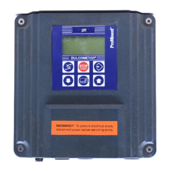
Page 5: Device Overview / Controls
Device Overview / Controls Display field measured variable Graphic display START/STOP Button CHANGE Button ENTER Button RETURN Button ® DULCOMETER DOWN STOP Button Button START D1C2-Cl-002-GB CHANGE button UP button To change over within a menu level To increase a displayed numerical and to change from one variable to value and to change variables (flashing another within a menu point. -
Page 6: Functional Description
Functional Description Brief functional description ® The DULCOMETER D1C is a device designed for measuring, displaying and controlling measures variables. With the corresponding expansion stage it can also process disturbance variables. The measured variables to be processed are: - pH, ORP - Standard signal, Temperature - Dissolved Oxygen - Chlorine, ClO... -
Page 7: Mounting / Installation
The aperture in the control panel for installing the device is defined in DIN 43700. We recommend a smaller aperture. In this way, the device is held more securely in place (reduced lateral play) and the seal is pressed more evenly. DED1C1S003 +0,5 +0,6 Aperture to Aperture to ProMinent DIN 43700 recommendation... - Page 8 Mounting / Installation To make aperture: As an installation aid, a drill/punch template at a scale of 1:1 is provided with the device for the purpose of optimally positioning the device on the control panel. With the aid of a spirit level, align the template in the corresponding position on the control panel and secure in this position.
- Page 9 Mounting / Installation Ø 8 x 50 deep drilled hole D1C1(W) 003 D 5.2.3 Control panel installation D1C W A 4 mm wide flange acting as the stop for the control panel together with an all-round groove for a seal is provided on the perimeter of the device.
- Page 10 Mounting / Installation Mounting with SN6 socket (depending on identity code) Corresponding to the order, an SN6 input socket may be preassembled on the device. This socket must first be removed Control panel in order to facilitate installation in the control panel. For this purpose, open device as described under Point 5.3.
- Page 11 Mounting / Installation 5.3.2 Electrical installation D1C W (wall mounting) Opening the housing The device should only be opened when it is mounted on a wall or installed in a control panel. To open the housing, initially, the four captive countersunk screws must be released. The upper section is additionally locked to the bottom section by means of snap hooks.
- Page 12 If the controller features an SN6 input (corresponding to identity code), the corresponding input socket is located in the rear row on the left side in a PG 11 threaded hole. Any ProMinent cable combination coax SN6 can be connected to this input.
-
Page 13: Technical Data
Technical Data Temperature specifications D1C D Control panel Wall mounting Permissible ambient temperature installation Basic version: 0 °C...50 °C -5 °C...45 °C Expansion version: with position feedback or with correction value via mA or with disturbance variable via mA 0 °C...45 °C -5 °C...40 °C D1C W Permissible ambient temperature... - Page 14 Technical Data Probe input via SN6 socket (X2.12 ... X2.9): Input resistance: Ω Other data same as for “Probe input via terminals” Standard signal input (all measured variables) (X2.12 ... X2.9): Input range: 0/4…20 mA (programmable) Input resistance: 50 Ω Accuracy: 0.5 % of input range Resolution:...
- Page 15 Technical Data Standard signal input for correction variable or disturbance variable mA (X1.16 ... X1.14): Galvanically isolated from other inputs and outputs Insulation voltage: 500 V Input range: 0/4…20 mA (programmable) Input resistance: 50 Ω Accuracy: 0.5 % of input range Resolution: 0.014/0.012 mA Supply voltage and current for external electronics:...
- Page 16 Technical Data Power relay output for alarm triggering (XR3): Type of contact: Changeover contact, noise-suppressed with varistors Load capacity: 250 V AC, 3 A, 700 VA Contact lifespan: >20 x 10 switching operations IMPORTANT The supply voltage applied at relays XR1-XR3 must be identical to the supply voltage of XP.
-
Page 17: Maintenance / Repair
Maintenance / Repair Safety information WARNING • The device or system must be disconnected from the power supply before starting any ® maintenance work. The DULCOMETER D1C does not feature a separate power switch! The power supply must therefore be interrupted by means of an external master switch or by a main fuse. - Page 18 Maintenance / Repair Fuse change D1C W: • The above-specified safety measures must be implemented (disconnection from mains!) before replacing the device fuse: The mains power fuse is located in a closed fuse holder (6) in the terminal box. Open device and set in “park position” Release bayonet catches of fuse holder Remove fuse and replace by new fuse Lock bayonet catch and close housing...
-
Page 19: Applicable Types Of Enclosure / Standards
Applicable Types of Enclosure / Standards Electric shock and moisture protection (IP) D1C D: Device in installed condition: Type of enclosure DIN 40050 - IP 54 D1C W: Device in sealed housing type of enclosure IP 65 in accordance with DIN VDE 0470 corresponding to EN 60529 and IEC 529 outer seal (control panel installation): type of enclosure IP 54 in accordance with DIN VDE 0470 corresponding to EN 60529 and IEC 529. -
Page 20: Spare Parts / Accessories
Plastics and scrapped electronic components are special waste and must be recycled! Used electronic components are accepted by municipal collection points set up by towns and municipal districts or ProMinent branches! With the exception of the electrical assemblies, the design of the device comprised few mechanical parts. -
Page 21: Ec Declaration Of Conformity
EC Declaration of Conformity... -
Page 22: Overview Of Terminal Arrangement
Übersicht Klemmenanordnung / Overview of terminal arrangement Klemmenanordnung Schalttafelgerät Terminal order switchboard mounting... - Page 23 Klemmenanordnung Wandgerät Terminal order wall mounting ACHTUNG Nicht die Klemmenbezeichnungen von X2 und X1 verwechseln! IMPORTANT Do not confuse the terminal designations X2 and X1!
-
Page 24: Terminal Diagrams
pH/Redox über Klemme / pH/ORP via terminals Klemmenanschluss für pH / Redox über Klemme Terminal connection for pH / ORP via terminals Frequenz-Ausgänge pH/Redox (ORP) Temperatur- Normsignal-Ausgang 1 (Pumpen) Eingang (Pt 100) 0/4-20mA mV-Eingang-Klemme Standard signal output 1 Frequency outputs Temperature mV-input terminal 0/4-20mA... - Page 25 pH/Redox über SN6-Eingang / pH/ORP via SN6 socket Klemmenanschluss für pH / Redox über SN6-Eingang Terminal connection for pH / ORP via SN6 socket Frequenz-Ausgänge pH/Redox (ORP) Temperatur- Normsignal-Ausgang 1 (Pumpen) Eingang (Pt 100) 0/4-20mA SN6-Eingang Standard signal output 1 Frequency outputs Temperature SN6-input...
- Page 26 F, Br , Cl , ClO , mA, mS/cm, pH*, Redox / ORP*, ºC* Klemmenanschluss für Terminal connection for F, Br , Cl , ClO , mA, mS/cm, pH*, Redox*, ˚C* Frequenz-Ausgänge Normsignal-Ausgang 1 Messgröße Temperatur- (Pumpen) 0/4-20 mA Normsignal-Eingang (mA) Eingang (Pt 100) Standard signal output 1 Frequency outputs...
- Page 27 Leitfähigkeit / conductivity Klemmenanschluss für Leitfähigkeit Terminal connection for conductivity Leitfähigkeits- Frequenzausgänge Normsignal-Ausgang 1 Temperatur- (Pumpen) Eingang Eingang 0/4-20mA Frequency outputs Standard signal output 1 Temperature Conductivity input (pumps) 0/4-20mA input 121110 9 Intern internal Extern external Netz Netz Mains power Mains power *** Korrekturgröße für mS/cm (vgl.
- Page 28 mit Grenzwertrelais / with limit value relays Klemmenanschluss mit Grenzwertrelais Terminal connection with limit value relay Leistungsrelais- Interne Spannungs- Leistungsrelais- Ausgänge versorgung Ausgang zur Alarmgabe Power relay Internal output Power relay output power supply for alarm triggering Intern internal Extern external Speise- Speise-...
- Page 29 mit Magnetventilen / with solenoid valves Klemmenanschluss mit Magnetventilen Terminal connection with solenoid valves Leistungsrelais- Interne Spannungs- Leistungsrelais- Ausgänge versorgung Ausgang zur Alarmgabe Power relay Internal output power supply Power relay output for alarm triggering Intern internal Extern external Speise- Speise- Speise- Speise-...
- Page 30 mit Stellmotor / with servomotor Klemmenanschluss mit Stellmotor Terminal connection with servomotor Stellungsrückmelde- Leistungsrelais- Leistungsrelais- Interne Spannungs- Eingang Ausgänge Ausgang zur versorgung Alarmgabe Position feedback Power relay Internal input output power supply Power relay output for alarm triggering 3 2 1 Intern internal Extern...
- Page 31 mit Normsignal-Ausgang 2, mit Pause / with standard signal output 2, with pause Anschlussdetails Normsignalausgang 2 / Digitaleingang Pause Connection details Standard signal output 2 / Digital input pause Normsignal- Digital- Ausgang 2 Eingang 0/4-20mA Digital input Standard signal output 2 10 9 8 Intern internal...
- Page 32 mit Störgröße / with disturbance variable Anschlussdetails Störgröße Connection details disturbance variable Normsignal-Eingang Digital- für Korrekturgröße oder Störgröße (mA) Eingang Standard signal input Digital input correction variable or disturbance variable (mA) Belegungsvarianten Assignment variants 16 15 14 7 6 5 16 15 14 Intern internal...
- Page 33 mit Korrekturgröße / with correction variable Anschlussdetails Korrekturgröße Connection details correction variable Temperatur- Normsignal-Eingang Eingang (Pt 100) für Korrekturgröße oder Störgröße (mA) Temperature Standard signal input input (Pt 100) correction variable or disturbance variable (mA) Belegungsvarianten Assignment variants 16 15 14 16 15 14 16 15 14 Intern...
- Page 35 ©1999 ProMinent Dosiertechnik GmbH · 69123 Heidelberg · Germany ® Operating Instructions DULCOMETER D1C, Part 1, issue 04/03 Subject to technical modifications · Printed in Germany ProMinent Dosiertechnik GmbH Im Schuhmachergewann 5-11 · 69123 Heidelberg · Germany Postfach 101760 · 69007 Heidelberg · Germany Tel.: +49 6221 842-0 ·...
Need help?
Do you have a question about the DULCOMETER D1CA and is the answer not in the manual?
Questions and answers