Table of Contents
Advertisement
Quick Links
- 1 Device Identification / Identity Code
- 2 Table of Contents
- 3 Device Overview / Controls
- 4 Operation
- 5 Calibrating the Chlorite Probe
- 6 Calibrating the Chlorite Probe (Zero Point and Slope)
- 7 Standard Signal Output 1
- 8 Complete Operating Menu
- Download this manual
See also:
Operating Instructions Manual
Operating Instructions
®
DULCOMETER
D1C
Part 2: Adjustment and Operation,
Measured variable chlorite
D1C2-Clt-001-GB
Type D
Type W
___ ___ ___ ___ ___ ___ ___ ___ ___ ___ ___ ___ ___
D1C A
Please enter the identity code of your device here.
Please completely read through operating instructions! · Do not discard!
The warranty shall be invalidated by damage caused by operating errors!
Part No. 987028
ProMinent Dosiertechnik GmbH · 69123 Heidelberg · Germany
BA DM 106 09/03 GB
Advertisement
Table of Contents

Related Manuals for ProMinent DULCOMETER D1CA


Summary of Contents for ProMinent DULCOMETER D1CA
- Page 1 Please enter the identity code of your device here. Please completely read through operating instructions! · Do not discard! The warranty shall be invalidated by damage caused by operating errors! Part No. 987028 ProMinent Dosiertechnik GmbH · 69123 Heidelberg · Germany BA DM 106 09/03 GB...
-
Page 2: Device Identification / Identity Code
Device Identification / Identity Code D1C A DULCOMETER ® Controller Series D1C / Version A Type of mounting Control panel installation 96 x 96 mm Wall mounting Operating voltage 230 V 50/60 Hz 115 V 50/60 Hz 200 V 50/60 Hz (only with control panel installation) 100 V 50/60 Hz (only with control panel installation) 24 V AC/DC Measured variable... -
Page 3: Table Of Contents
Contents / General User Information Page Device Identification / Identity Code ....................2 General User Information ........................3 Device Overview / Controls ........................4 Functional Description ......................... 5 Display Symbols ........................... 6 Operation .............................. 7 Restricted Operating Menu ........................8 Overview .............................. -
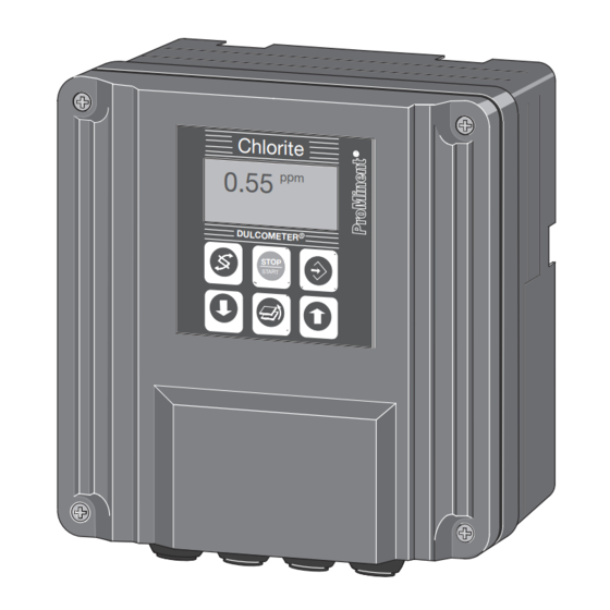
Page 4: Device Overview / Controls
Device Overview / Controls Display field Measured variable chlorite Graphic display Chlorite "Start/Stop" Button "Change" Button "Enter" Button "Branch back" Button ® DULCOMETER "Up" Button STOP "Down" Button START D1C2-Clt-002-GB CHANGE Button UP Button To change over within a menu level To increase a displayed numerical and to change from one variable to value and to change variables (flashing... -
Page 5: Functional Description
Functional Description NOTE Please refer to the description of the complete operating menu in Section 8 for a detailed description of the individual characteristics of the DULCOMETER ® D1C controller! Operating Menu The D1C controller permits settings to be made in two different menus. All values are preset and can be changed in the complete operating menu. -
Page 6: Display Symbols
Display Symbols ® The display of the DULCOMETER D1C controller uses the following symbols: Description Comment Symbol Limit value transgression Symbol Relay 1, upper left Symbol Relay 1, lower left Symbol Relay 2, upper right Symbol Relay 2, lower right Metering pump 1 (chlorite) Symbol Control off... -
Page 7: Operation
Operation The various menus are selected with Permanent the CHANGE button display 1 The menu is started with the ENTER button Permanent BRANCH BACK to permanent display display 2 or to relevant setting menu Calibration Calibration notes menu Various Access code, correct Setting menus Parameter Access code... -
Page 8: Restricted Operating Menu
Restricted Operating Menu / Overview The restricted operating menu permits simple operation of the most important parameters. The following overview shows the settings which can be selected: Permanent display 1 0.55 mea. val 0.55 ppm Permanent display 2 Positive values of setting variable: chlorite feedfwd: 70 % only with control... -
Page 9: Description
Restricted Operating Menu / Description Permanent display 1 0.55 mea. val. 0.55 ppm Permanent display 2 Positive values of setting variable: chlorite feedfwd: 70 % only with control Negative values of setting variable: De-Clt ctrlout: 59 % (w = setpoint) (chlorite destruction) 0.40 ppm D1C2-Clt-011-GB... - Page 10 Restricted Operating Menu / Description Limits Access to all setting menus can be blocked with an access code ! limits limit 2 upper setting ? 5.00 ppm limit 1 lower 1.00 ppm D1C2-Clt-014-GB Possible values Initial value Increment Lower value Upper value Remarks Type of limit trans-...
- Page 11 Restricted Operating Menu / Description Possible values Initial value Increment Lower value Upper value Remarks Setpoint 0.50 ppm 0.01 ppm lower limit upper limit 2 setpoints necessary measuring range measuring range for control with dead zone. Setpoint 1 > setpoint 2 Control parameter xp 10 % 500 %...
-
Page 12: Complete Operating Menu
Complete Operating Menu / Overview All parameters of the controller can be set in the complete operating menu (access see previous page). The following overview shows the settings which can be selected: Permanent display 1 0.55 Permanent display 2 mea. val 0.55 ppm feedfwd: 70 % only with control... - Page 13 Complete Operating Menu / Description Permanent display 1 0.55 mea. val. 0.55 ppm Permanent display 2 Positive values of setting variable: chlorite feedfwd: 70 % only with control Negative values of setting variable: De-Clt ctrlout: 59 % (w = setpoint) (chlorite destruction) 0.40 ppm D1C2-Clt-018-GB...
- Page 14 Complete Operating Menu / Description Error message Condition Effect – Calibration Clt not possible! slope too low Calibrate again Probe slope too low (<25 % of norm slope) – Calibration Clt not possible! slope too high Calibrate again Probe slope too high (>300 % of norm slope) DPD value too low DPD <2 % of...
- Page 15 Complete Operating Menu / Description Possible values Initial value Increment Lower value Upper value Remarks Standard signal input 4 mA 0 mA lower signal limit 4 mA Allocated measured value lower 0 ppm 0.01 ppm -0.20 ppm 2.20 ppm for CLT1-mA-2 ppm 0 ppm 0.001 ppm -0.05 ppm...
- Page 16 Complete Operating Menu / Description Relay for power control Access to all setting menus can be blocked with an access code ! Only with limit relay, solenoid valve relay or servomotor relays relay adjustment control setting ? relay1: solenoid valves: relay2: SV1 chlorit SV2 De-Clt...
- Page 17 Complete Operating Menu / Description Cycle Solenoid min. time Actuating valve variable: 80 % = 0.80 Cycle Cycle Actuating variable: 50 % = 0.50 Cycle ® The switching time of the DULCOMETER D1C (solenoid valve) depends on the actuating variable and the “min.
- Page 18 Complete Operating Menu / Description Limit values Access to all setting menus can be blocked with an access code ! limits fault limit 2 upper limits hyst.: 0.20 ppm 1.50 ppm setting ? ∆t on: limit 1 lower control: 0.10 ppm relay 1 relay 2 - active closed...
- Page 19 Complete Operating Menu / Description Servomotor Activation of the servomotor must be carried out with the same meticulous care as taken when calibrating a measuring probe. The operating range is defined by the total resistance range of the feedback potentiometer. The maximum limit of the range actually used is set by defining the control range. CAUTION To ensure correct operation, the activation time of the actuator used should not be less than 25 seconds for the control range from 0…100 %!
- Page 20 Complete Operating Menu / Description Control Access to all setting menus can be blocked with an access code ! Note: The controlled variable is recalculaed every second. Only suitable for prosecc with time constants greater than 30 s ! Only with control Positive values of setting variable: chlorite Negative values of setting variable: De-Clt control...
- Page 21 Complete Operating Menu / Description Feed forward control Access to all setting menus can be blocked with an access code ! feedforward ctrl. feedforward ctrl. feedforward ctrl. feedforward ctrl. setting ? Hz / mA rated value disturb. variable 10 Hz 10.00 Hz additive feedforward ctrl.
- Page 22 Complete Operating Menu / Description Standard Signal Output 1 Access to all setting menus can be blocked with an access code ! Control with standard signal control mA output 1 control output control output Only with standard signal output positive chlorit 0 mA = mA output 1 mA output 1...
- Page 23 Complete Operating Menu / Description General setting Access to all setting menus can be blocked with an access code ! general setting ident-code: D1CA alarm relay pause normal information DxIxxxxxxxxxx active - active... closed software version - alarm off D1C-B1 FW-4.90 - td: 0 min access c.: 5000...
- Page 24 Complete Operating Menu / Description Standard Pause ® If the pause-switch is off, the DULCOMETER D1C sets the operating outputs to “0” for as long as the pause-switch is off or for a set time-delay t (if t is set to > 0 min). Whilst the pause-switch is off, the D1C establishes the P-proportion in the background.
-
Page 25: Ec Declaration Of Conformity
EC Declaration of Conformity... - Page 26 10 Fehler / Hinweise / Fehlerbehebung...
- Page 28 Operating Instructions DULCOMETER D1C, Part 2/I, Issue 09/03 Subject to modifications · Printed in Germany ProMinent Dosiertechnik GmbH · Im Schuhmachergewann 5-11 · 69123 Heidelberg · Germany Postfach 101760 · 69007 Heidelberg Phone: +49 (6221) 842-0 · Fax: 842-419 info@prominent.de · www.prominent.de...
Need help?
Do you have a question about the DULCOMETER D1CA and is the answer not in the manual?
Questions and answers