Lennox Prodigy 2.0 Application Manual
M3 unit controller
Hide thumbs
Also See for Prodigy 2.0:
- Installation (1 page) ,
- Installation, operation & maintenance manual (17 pages)
Table of Contents
Advertisement
Litho U.S.A.
©2014
®
Prodigy
2.0 (M3 Unit Controller) Application Guide (Advanced Features)
To insure correct voltage phasing before start up:
1) use refrigerant pressure gauges to check proper compressor operation and,
2) check arrow label for blower rotation.
Compressor damage will be the responsibility of the installer.
ELECTROSTATIC DISCHARGE (ESD)
Precautions and Procedures
507242-01
7/2014
CAUTION
CAUTION
Electrostatic discharge can affect electronic components. Take precautions
during unit installation and service to protect the unit's electronic controls.
Precautions will help to avoid control exposure to electrostatic discharge by
putting the unit, the control and the technician at the same electrostatic
potential. Neutralize electrostatic charge by touching hand and all tools on an
unpainted unit surface before performing any service procedure
Page 1
®
PRODIGY
2.0 APPLICATION
GUIDE
Advertisement
Table of Contents

Related Manuals for Lennox Prodigy 2.0


Summary of Contents for Lennox Prodigy 2.0
- Page 1 ® PRODIGY 2.0 APPLICATION 507242-01 7/2014 GUIDE Litho U.S.A. ©2014 ® Prodigy 2.0 (M3 Unit Controller) Application Guide (Advanced Features) CAUTION To insure correct voltage phasing before start up: 1) use refrigerant pressure gauges to check proper compressor operation and, 2) check arrow label for blower rotation.
-
Page 2: Table Of Contents
Table Of Contents 1. Prodigy 2.0 M3 Unit Controller Description .......... - Page 3 3.5.1. Electric Heat Operation ........... . . Page 22 3.5.2.
- Page 4 9.4. Supply Constant Air Volume (CAV) with Zone Bypass Damper Control ....Page 46 9.4.1. Bypass Damper Actuator ........... . Page 46 9.4.2.
- Page 5 ........Page 77 19.1.4. CAV Units in Single-Zone Applications with a Lennox Room Sensor (4 Heat / 4 Cool) Page 79 19.1.5.
-
Page 6: Prodigy 2.0 M3 Unit Controller Description
1. Prodigy 2.0 – M3 Unit Controller Description The M3 Unit Controller provides all rooftop unit control functions to insure its safe and reliable operation. It also provides status and diagnostic information to facilitate troubleshooting. The controller's programmable parameters allow adjustment of time delays and set points that enable advanced features. -
Page 7: Main Controller Operation
2. Main Controller Operation 2.1. Control Type - Thermostat The M3 Unit Controller will operate the system from a wired thermostat, room sensor, zoning system using L Connection Zoning System based on the System Mode selected in SETTINGS > CONTROL > CONTROL TYPE = WIRED THERMOSTAT. -
Page 8: Heating Stages
2.1.2. Heating Stages The M3 Unit Controller default thermostat operation is for two heating stages. See table 3 for gas heat units and table 4 for electric heat units. The M3 Unit Controller allows three different staging options: Go to SETTINGS > RTU OPTION > EDIT PARAMETER =112 (HEAT STAGING OPTION) •... - Page 9 Table 5. Menu Interface (Level 1 - SETUP) LCONN ADDRESS = X • NETWORK SENSOR CO2 = YES OR NO • NETWORK SENSOR RELATIVE HUMIDITY = YES OR NO • NETWORK SENSOR TEMPEATURE = YES OR NO • ROOM SENSOR OCC BLOWER MODE= AUTO CYCLES OR ON- NETWORK = RTU CONTROL MODE = CONTINUOUS 1, 2 OR 3 *...
-
Page 10: Room Sensor Back-Up Mode Set Points
Figure 3. Backup Mode 2.2.3. Room Sensor Back-Up Mode Set Points The following set points are available when primary mode is set to NETWORK THERMOSTAT and the backup sensor mode is set to either RETURN AIR BACK or ROOM SENSOR. All available set points have a range of 40.0°F to 95.0°F. The listed values below are defaults. -
Page 11: L Connection Network Back-Up Mode Requirements
2.2.4. L Connection Network Back-Up Mode Requirements Go to SETUP > NETWORK INTEGRATION wizard to configure a back up mode option. Use table 6 references the wizard path to the backup mode setting. Table 6. Menu Interface (Level 1 - SETUP) LCONN ADDRESS = X •... -
Page 12: Room Sensor Parameters
2.2.8. Room Sensor Parameters Any of the parameters listed in table 7, can be directly modified using the following method: Go to SETTINGS > RTU OPTION > EDIT PARAMETER = Table 7. Room Sensor Parameter Summary Control Parameter Control Value Unit Description Screen Name... - Page 13 Table 7. Room Sensor Parameter Summary Control Parameter Control Value Screen Name Short Description Min. Default Max. Unit Unit Description Description • Backup occupied heating set point. • Used if the communications link is lost for 5 minutes between the M3 and Net Occupied Heating Set work Control Panel.
- Page 14 Table 7. Room Sensor Parameter Summary Control Parameter Control Value Screen Name Short Description Min. Default Max. Unit Unit Description Description • Cooling stage 3 differential. Used only with room sensor applications. Cooling Stage 3 COOL STAGE3 DIFFER 0.00 1.50 3.00 °F •...
- Page 15 Units With Economizer: Cooling stage-up timers 15 minutes. Parameter 101 - Parameter 103 C1=Free Cooling 2°F Diff Cooling stage-down timers 15 minutes. Parameter 104 C2=Compressor 1 C3=Compressor 2 Parameter 147 C4=Compressor 3 + 4 1.5°F Diff C1=Cooling Stage 1 Parameter 144 C2=Cooling Stage 2 C3=Cooling Stage 3 1°F Diff...
-
Page 16: Unit Component Operation
3. Unit Component Operation 3.1. Compressor Protection and Delays 3.1.1. Compressor Minimum Run and Off Times Energence Ultra-High Efficiency Units Energence UltraHigh Efficiency Units have both compressor Minimum Run Time (default 240 seconds) and Minimum OFF Time (default 300 seconds) always enabled. This configuration cannot be altered, but values can be adjusted (refer to the Appendix C for details) Go to SETTINGS >... -
Page 17: Low Pressure Switches (S87, S88, S97 And S98)
3.1.4. Thermal Protector Switches (S5, S8, S31 and S180) 3.1.4.1. Energence Ultra-High Efficiency Units This model has one pressure switch (S4) that is connected in series with two temperature switches (S5 and S8) (see figure to right). If pressure switch trips, both compressors are de-energized. -
Page 18: Combustion Air Inducer Proof Switch (S18 And S45)
3.2.3. Combustion Air Inducer (CAI) Proof Switches (S18 and S45) 3.2.3.1. Open Proof Sequence of Operations The M3 Unit Controller will set alarm 166 and/or 167 if either S18 or S45 are not proved open while the combustion air blower is not energized. If gas heat demand is still present, the M3 Unit Controller will attempt to prove either S18 or S45 are in a open condition every 60 seconds. -
Page 19: Gas Valve Sensor
3.2.4. Gas Valve Sensor Activation Feedback If M3 Unit Controller does not detect that gas valve is energized within two minutes after a heating demand, it will display and store error code 58 for gas heat section 1 and alarm 68 for gas heat section 2. If the gas valve is energized and de-energized three times (default) during a single heating demand, the M3 will display and store error code 59 for the gas heat section 1 and alarm 60 for gas heat section 2. -
Page 20: Safety Switch Input (A42-Optional)
3.3.4. Safety Switch Input (A42-Optional) The M3 Unit Controller has 24VAC optional inputs (D1-2 or DI-3) which may be used for additional safety switches (such as a blower overload, loss of phase protector, or supply duct high pressure limit switch). Wire the safety switch in series with the input. -
Page 21: Unoccupied Or Night Setback Mode
3.3.10. Blower Off-Delay • For electric heat units, the blower off is delayed 20 seconds (default) from the time the heating call is terminated. The blower delay is adjustable using Parameter 60. Parameter range setting is 0 to 300 seconds. Go to SETTINGS > RTU OPTION >... -
Page 22: Electric Heat Operation-Electric / Electric Units
3.5. Electric Heat Operation—Electric / Electric Units 3.5.1. Electric Heat Stage Delay Operation First-stage heating demand energizes first-stage electric heat (K15 and K17). Second-stage heating demand energizes second-stage electric heat (K16 and K18). When first-stage and second-stage heating demands are simultaneous, a delay will occur between stage one and two (Parameter 62). -
Page 23: Optional Supply Static Pressure Sensor
4.5. Optional Supply Static Pressure Sensor The supply duct differential static pressure sensor (A30) is an analog sensor with a 0-10VDC output over a range of 0-5"w.c as shown in the following table. The sensor is powered with 24VAC. Pressure "w.c. DC Voltage Pressure "w.c. - Page 24 Table 11. Number of Compressors/Fans and Fan Layout Fan Layout Models Compr. Fans Size LCH, LGH 36H, 48H and 60H 1 (2 step) (variable) A BOX LCH, LGH 36S, 48S, 60S and 72H LCH, LGH 090, 092U, 102, 120, 120U and 150 B BOX LCH, LGH 094U, 120U, 122U and 3 (2 out...
- Page 25 Table 12 .LCH and LGH 36S,48S,60S,72H Low Ambient Fan Operations Models Associated Compressor Fan Control LCH, LGH 36S, 48S, 60S and 72H On with S11 Table 13. LCH and LGH 090,102,120,150 Low Ambient Fan Operations Low Ambient Control Models Associated Compressor OD Temp <...
-
Page 26: Energence High Efficiency A
6. Dehumidification Operation Dehumidification mode is a combination of cooling to dehumidify and heating to maintain space temperature. Supermarket ® reheat uses gas heat and Humiditrol units route hot discharge gas to a reheat coil downstream of the evaporator. A gas ®... - Page 27 0 - 10VDC = 0-100% relative humidity J298A P298 AI-1 A91 HUMIDITY SENSOR DO-1 Two separate shielded cables required. One wire of the two pairs is not connected. DO-2 Figure 6. Relative Humidity Sensor Diagram Go to SETTINGS > RTU OPTION > EDIT PARAMETER = 106 (DEHUMID SETPOINT) and 107 (DEHUMID DEADBAND) (see paragraph 6.3.
-
Page 28: Third-Party Digital Output To Control Dehumidification
6.3. Third Party Digital Input to Control Dehumidification 1. Go to SETUP > INSTALL. Set Configuration ID1, position 1 to H for Humiditrol option. Follow the wizard until sensor type option is prompted and select REHEAT DI4. 2. An alternate method is to Go to SETTINGS >... -
Page 29: Selecting Minimum Low And Minimum High Damper Positions
Table 20. Summary Of Dehumid Parameter Options Control Parameter Control Value Short Description Screen Name Min. Default Max. Unit Description Dehumidification Mode No reheat. Supermarket reheat using De-Humidistat (wired thermostat mode only) Supermarket reheat using relative humidity 0 - No sensor. -
Page 30: Compressor And Humiditrol ® Operation
6.6. Compressor and Humiditrol Operation Table 22. 2-Compressor Humiditrol Default Operation (Using 2-Stage Wired Thermostat) Demands Condition Unit Operation Free Air Compressor Blower Speeds Reheat Damper Humidity Valve 1 Thermostat Trigger Cool Cool (Economizer) Sensor Vent Heat Unoccupied Closed Occupied Minimum Modulate up to Suitable... - Page 31 Table 24. 3-Compressor Humiditrol Default Operation (using 2Stage Thermostat) Demands Condition Unit Operation Blower Speeds Compressor Free Air Damper (Economizer) Trigger Cool Cool Cool Cool Vent Heat Unoccupied OFF OFF OFF Closed Occupied OFF OFF OFF Minimum Modulate up to Suitable OFF OFF OFF Maximum...
- Page 32 Table 26. 3-Compressor Humiditrol Default Operation (using 4Stage Thermostat with Zone Sensor) Demands Condition Unit Operation Blower Speeds Compressor Free Air Damper (Economizer) Trigger Cool Cool Cool Cool Vent Heat Unoccupied OFF OFF OFF Closed Occupied OFF OFF OFF Minimum Modulate up to Suitable OFF OFF OFF...
- Page 33 Table 27. 4-Compressor Humiditrol Default Operation (using 2stage Thermostat) Demands Condition Unit Operation Blower Speeds Compressor Free Air Damper (Economizer) Trigger Cool Cool Cool Cool Vent Heat Unoccupied OFF OFF OFF OFF Closed Occupied OFF OFF OFF OFF Minimum Modulate up to Damper position Suitable OFF OFF OFF OFF...
- Page 34 Table 28. 4-Compressor Humiditrol Default Operation (using 3stage Thermostat) Demands Unit Operation Free Air Damper Blower Speeds (Economizer) Compressor Trigger Cool Cool Cool Cool Vent Heat Unoccupied OFF OFF OFF OFF Closed Occupied OFF OFF OFF OFF Minimum Modulate up to Suitable OFF OFF OFF OFF Maximum...
- Page 35 Table 29. 4-Compressor Humiditrol Default Operation (using 4stage Thermostat, DDC with Room Sensor) Demands Unit Operation Free Air Damper Blower Speeds (Economizer) Compressor Trigger Cool Cool Cool Cool Vent Heat UNOCP OFF OFF OFF OFF Closed OFF OFF OFF OFF Minimum Modulate up to Suitable...
-
Page 36: Economizer
7. Economizer 7.1. General The economizer, when configured, controls: • Damper position, which determines how much outdoor air is used to meet free cooling or indoor air quality requirements, • Optional power exhaust fans. On a cooling demand, outdoor air is used for free cooling instead of first-stage compressor(s) when outdoor air is suitable. 7.2. -
Page 37: Enabling Economizer And Settings
Configuration ID 1, position 2 needs to be set to M. The damper will open to the specified position during the occupied time period and close during the unoccupied time period. NOTE - When equipped with Motorized Outdoor damper Air Damper, Prodigy 2.0 provides only Demand Control Ventilation. Free Cooling/Economizer function is not available. -
Page 38: Economizer Checkout
7.10. Economizer Checkout The following checkout procedures are completed with unit energized. Confirm proper operation of the heartbeat LED. Step 1 will determine whether the economizer is allowing full damper travel. Use step 2 when the damper does not respond to step Steps 3, 4, 5, and 6 checkout the operating modes;... - Page 39 Step 5. ALL TEMPERATURE MODES OF OPERATION In the Economizer – Temperature mode, the damper opens for free cooling when the outdoor air temperature is: • Less than return air temperature by at least a difference of (Parameter 161 - ECON FRCL TMP OFFST) if Temperature Offset mode is selected •...
-
Page 40: Demand Control Ventilation
7.11. Demand Control Ventilation 7.11.1. General A field-provided and installed indoor air quality (IAQ) sensor can be used with the modulating economizer or OADM to control carbon dioxide levels in the conditioned space. The carbon dioxide level in a space is an indicator of the number of people occupying a room. -
Page 41: Parameter Adjustments
7.11.4. Parameter Adjustments Default indoor air quality economizer operation is based on common or average applications. Adjustments may be made to the indoor air quality parameters to alter operation or meet required specifications. Use the user interface to change Parameter 117 through 119. Go to SETTINGS > RTU OPTIONS > EDIT PARAMETER Select a demand control ventilation mode with Parameter 134. - Page 42 Table 32. Demand Control Ventilation Parameters Control Parameter Control Value Parameter Short Description Screen Name Min. Default Max. Units Units Description Description Demand Control Ventilation Outdoor Low outdoor air temp. where DCV LO TMP OV ST CL Air Control Low -31.0 40.0 132.0...
-
Page 43: Power Exhaust Operation
7.11.4.1. Set Point Control Option Set point control mode is commonly used in areas with high occupancy and frequent change out such as classrooms or conference rooms. In applications requiring this on/off damper response to carbon dioxide levels, set the start open (Parameter 118 - DCV DAMP START OPEN) set point higher than the full open (Parameter 119 - DCV DAMP FULL OPEN) set point. -
Page 44: Supply Air Delivery
9. Supply Air Delivery 9.1. Blower Delays The following is summary of blower delay options, For more details refer to sections 3.3.9 and 3.3.10. 9.1.1. Gas / Electric Units The blower default delay is 40 seconds (Parameter 66 HT GAS BLR ON DELAY) after the gas valve is energized and a default of 120 seconds (Parameter 67 ... - Page 45 • High Efficiency Energence A Box Units with Smart Airflow™ (Advance Airflow) Applications that have Smart Airflow™ option installed and with successful blower calibration, will run the blower at a calculated percent output to deliver the airflow as set by the installer. The table below shows the default Airflow set points parameter. Parameter 18 by default is 0 but needs to be set to a valid value during installation.
- Page 46 Supply Constant Air Volume (CAV) with Zone Bypass Damper Control Configuration ID 2 position 7 must be set to Y to enable Prodigy 2.0 Zone bypass operation with Constant Air Volume. This configuration is used for L Connection or third-party zoning systems that utilize a blower bypass damper for controlling duct static pressure.
-
Page 47: Analog Output Control
9.4.2. Analog Output Control The analog output on the M3 Unit Controller (P2594) is set to closed loop PID or staged control when configured for Constant Air Volume bypass damper (Configuration ID 2, position 7 must be set to Y). The closed loop PID method used by the M3 Unit Controller has three constants manual resets;... - Page 48 9.4.2.5. Tuning In the event that the PID loop requires tuning, the following two methods are recommended depending on the severity of the problem: 1. In most cases the parameters will only need a small adjustment. In that case use the following table as a basic guide. Table 41.
-
Page 49: Discharge Air Control
10. Discharge Air Control 10.1. Cooling The discharge air control cooling option automatically cycles up to 4-stages of cooling to maintain a discharge air control cooling set point. • When an economizer is installed, adjust free cooling set point Parameter 159 approximately 2 degrees lower than Discharge Air Control Cooling set point. -
Page 50: Discharge Air Control Cooling (Dacc) Outdoor Air Temperature Reset
The DACC OAT Reset and free cooling set point can be automatically reset when outdoor air temperature becomes cooler. • For DACC OAT Reset, use the Lennox UC software to access Parameter 287 and enable DACC Outdoor Air Temperature Reset. -
Page 51: Discharge Air Control Cooling (Dacc) Total Reset Limit
EXAMPLE: The application calls for the discharge air occupied set point Parameter 180 to be 55.0°F when Return Air Temperature is 70.0°F or higher. When the Return Air Temperature drops below 70°F, the set point needs to increase proportionately with the Outdoor Air Temperature decrease (maximum set point increase of 10°F). The 10.0°F Return Air Temperature difference is called Parameter 203 and the set point increase of 10.0°F is called the Parameter 204. - Page 52 Table 42. Discharge Air Cooling Parameters Summary Control Parameter Control Value Unit Description Short Description Screen Name Min. Default Max. Unit Description Discharge Air Control Discharge Air Control Cooling set point during DACC UNOCC SETPOINT Cooling Un 40.0 65.0 100.0 °F unoccupied period.
- Page 53 Table 42. Discharge Air Cooling Parameters Summary Control Parameter Control Value Unit Description Short Description Screen Name Min. Default Max. Unit Description Discharge • Discharge Air Control Cooling return air Air Control reset proportional band. Cooling Re DACC RAT RS PRP BND 10.0 30.0 °F...
-
Page 54: Heating
10.2. Heating The discharge air control heating option automatically cycles up to four-stages of heating to maintain a discharge air control heating set point. • Discharge Air Control Heating option applies to gas/electric and electric /electric units only; Discharge Air Control Heating is not allowed with heat pumps units. -
Page 55: Discharge Air Control Heating (Dach) Outdoor Air Temperature Reset
10.2.1. Discharge Air Control Heating (DACH) Outdoor Air Temperature Reset Note: Parameter 287 cannot be modify directly from the M3 Unit Controller interface. • Using the Lennox UC software, access Parameter 287 and enable DACH Outdoor Air Reset. If using the Lennox UC software. •... -
Page 56: Discharge Air Control Heating (Dach) Total Reset Limit
Note: Parameter 287 cannot be modify directly from the M3 Unit Controller interface. • Using the Lennox UC software, access Parameter 287 and enable DACH Return Air Temperature Reset. • The Discharge Air Control Heating set point can be automatically reset when return air temperature becomes warmer. - Page 57 Table 43. Discharge Air Heating Parameters Summary Control Parameter Control Value Screen Name Min. Default Max. Unit Unit Description Description Discharge Air Control Heating Discharge Air Control Heating and Fresh Air DACH FAH STG UP TMR Stage-Up Time Heating stage-up time delay. Delay Discharge Air Control Heating...
-
Page 58: Third-Party Zoning
11. Third-Party Zoning The M3 Unit Controller is only compatible with bypass damper actuators specified in the Product Specification bulletin. Figure 19 is a Constant Air Volume with bypass damper unit wiring summary. In addition to providing bypass damper control (Constant Air Volume units), the M3 Unit Controller provides discharge air control for cooling and/or heating. -
Page 59: Discharge Air Control Heating Outdoor Air Reset
11.4.1. Discharge Air Control Heating Outdoor Air Reset The outside air reset saves energy by gradually decreasing the discharge air set point as the outside air temperature increases. Refer to section 10.2.1. for further details. 11.4.2. Discharge Air Control Heating Return Air Reset The return air reset reduces the possibility of overheating by gradually decreasing the discharge air set point as the return air temperature increases. -
Page 60: Bacnet
The optional M3 Unit Controller BACnet Module allows communication between the M3 Unit Controller and a BACnet MSTP network. The BACnet module conforms to the BACnet application specific controller (B-ASC) device profile. A Lennox non-communicating room sensor, a BACnet network room sensor, or a BACnet thermostat may be used to send the room temperature or thermostat demands to the M3. -
Page 61: Analog Output Objects
ROUTER Cable type - twisted pair with shield, 22 awg minimum, (not terminated) (terminated) (terminated per mfg Belden #88761 or #8761 (Lennox 27M19, 94L63, 68M35). instructions) Figure 21. Terminating ends of daisy-chained networks 12.4. Analog Output Objects Optional Properties Supported:... -
Page 62: Analog Value Objects
12.5. Analog Value Objects Optional Properties Supported: None Optional Writable Properties: Present_Value Table 45. Analog Value Objects List Object Min. Max. Valid Values within Object Name Units Note Value Value Range 9600, 19200, 38400, Baud Rate Setting None 9600 76800 38400 default 76800 Heating Occupied Set... -
Page 63: Analog Input Objects
12.6. Analog Input Objects Optional Properties Supported: None Optional Writable Properties: Out_Of_Service (AI239 - AI252, AI274 - AI285 only) Table 46. Analog Input Objects List Object ID Object Name Units Data Range Mac Address None 0 − 127 IMC Address None 1−31 IMC Version[4]... - Page 64 Table 46. Analog Input Objects List Object ID Object Name Units Data Range Most Recent Error 10 None 1 − 255 Space Carbon Dioxide Sensor (Effective) Parts−per−million 0 − 2000 Space Carbon Dioxide Sensor (Local) Parts−per−million 0 − 2000 Space Humidity (Effective) Percent 0 −...
- Page 65 Table 47. Lennox Proprietary Objects - Compressor (Object ID: 136) Property Property ID Data type and range Access Description Numeric code that identifies the object (unique within Object_Identifier Integer (0-4194302) Read Only Lennox BACnet Device). character string of 1 character (min.)
- Page 66 Table 49. Lennox Proprietary Objects - Heating (Object ID: 130) Property Property ID Data type and range Access Description Numeric code that identifies the object (unique within Object_Identifier Integer (0-4194302) Read Only Lennox BACnet Device). character string of 1 character (min.)
- Page 67 A value of 0 means no error while any Lennox_Object_Error Integer (0 - 255) Read Only non-zero value represent an error. Table 51. Lennox Proprietary Objects - Discharge Air (Object ID: 133) Property Property ID Data type and range Access...
-
Page 68: Load Shedding Options
Table 52. Lennox Proprietary Objects - Space Air (Object ID: 133) Property Property ID Data type and range Access Description Numeric code that identifies the object (unique within Object_Identifier Integer (0-4194302) Read Only Lennox BACnet Device) Character string of 1 character (min.) -
Page 69: Service Relay
14. Service Relay 14.1. Service Relay Operation The M3 Unit Controller Service Relay output (A55_P298-8) default operation indicates that service is required. If the default operation is not required, the Service Relay output may be used as a control output. Use Parameter 186 to choose the input which will trigger the Service Relay output. -
Page 70: System Relative Humidity Options
Table 55. Service Relay Options Control Parameter Control Value Screen Name Min. Default Max. Unit Unit Description Description Service Output Set Point for SRV OUTPT SP RH Service Output Set Point for Relative Humidity Relative Humidity Service Output SRV OUTPT SP TEMP Set Point -31.0 51.0... - Page 71 Example 1: Use the Service output to energize a dehumidifier at 60% relative humidity and turn off at 55% relative humidity. (Refer to figure 22.) 1. Determine: Dehumidifier On Parameter 186 - Input Source X to option “7" (relative humidity) Algorithm Y to option “0"...
-
Page 72: Control Parameters
Fans BASED HVAC Lights Figure 25. L Connection Network SYS BUS TERMINAL S-BUS TERMINAL SYS BUS TERMINAL BLOCK ON LENNOX BLOCK ON LENNOX BLOCK ON LENNOX CONTROLLERS IMC (M1-7, PRODIGY M2 OR M3 CONTROLLERS IMC M1-8, NTC, BC AND ZONE... -
Page 73: Calibration
™ 18. Advanced Airflow System (Smart Airflow ) in High Efficiency A Box (3-5 Ton units) The optional factory installed Advanced Airflow System employs a pressure sensor equipped economizer and an ECM blower motor. This feature enables the Prodigy M3 Unit Controller to accurately measure and control the Supply Airflow and Outdoor Airflow. -
Page 74: Outdoor Airflow (Oa) Measurement And Control
18.3. Outdoor Airflow (OA) Measurement and Control Target OA is calculated for all the modes (DCV, Free Cooling, Minimum Run) individually when there is a change in the supply airflow target or minimum and maximum OA targets (Parameters 237, 241 and 242). DCV and minimum run modes will be active only if occupied. - Page 75 18.4. Airflow Target Minimum - Maximum Settings ENERGENCE A BOX WITH SMART CFM VALUES BY MODEL Parameter AIRFLOW™ (ADVANCE AIRFLOW) NOTES Number (LCH/LGH) SMOKE DEFAULT CFM 1200 1600 2000 SUPPLY AIRFLOW HEAT TARGET 1200 1600 2000 For both gas & electric heating. HIGH SPEED TARGET (COOLING HI) 1080 1440...
-
Page 76: Sequence Of Operation
Constant volume units in either single-zone or bypass zoning applications can use this control mode. To operate correctly, a Lennox or third-party thermostat or unit control must provide the following wiring connections to the M3 Unit Controller: 1. Ventilation demand 2. -
Page 77: Operations Common To All Rooftop Units
Although not as common, constant volume units in either single-zone or bypass zoning applications may also use this control mode. To operate correctly, a Lennox or third-party thermostat or unit control must provide the following wiring connections to the M3 Unit Controller: 1. - Page 78 Unit Controller memory, have factory default settings, and may be adjusted at start up. The user can change these settings ® either locally or remotely through Lennox L Connection Network Unit Controller Software. The user will not have the ability to adjust the settings through third-party software or control devices.
- Page 79 19.1.4.1. Unit Controller Operation When using a Lennox room sensor with the M3 Unit Controller operating in room sensor mode, a packaged rooftop unit can provide up to four stages each of mechanical heating and cooling operation. The room sensor provides space temperature information to the M3 Unit Controller.
- Page 80 19.1.4.5. Heating Demand (General Operation) The M3 Unit Controller directly monitors space temperature through the room sensor. Based on this information, the M3 Unit Controller turns on or off the heating stages to maintain the desired temperature set point. Increasing heating stages provides additional heating capacity while decreasing heating stages provides less heating capacity.
- Page 81 19.1.5. Constant Air Volume Units in Single-Zone Applications with a Wired Thermostat or Third-Party Unit Controller (2-Heat / 2-Cool) 19.1.5.1. Unit Controller Operation When using a two-stage heat/ cool thermostat or third-party temperature control with the M3 Unit Controller in the thermostat mode, a packaged rooftop unit can provide up to two stages of mechanical heating and cooling operation.
- Page 82 The discharge supply air temperature set point resides in the M3 Unit Controller, has a factory default setting, and can be adjusted at start-up. The user can adjust the set point either locally or remotely with Lennox' L Connection Network Unit Controller software or at the M3 Unit Controller board.
- Page 83 M3 Unit Controller, has a factory default setting, and may be adjusted at start up. The user can adjust the set point either locally or remotely with Lennox' L Connection Network Unit Controller software or at the M3 Unit Controller board.
- Page 84 The following sequence of operation information is specific to constant air volume units in bypass zoning applications. 19.1.7.3. Supply Duct Bypass Damper To maintain accurate supply duct static pressure control, constant volume units in bypass zoning applications use a bypass damper between the supply and return air ducts.
-
Page 85: M3 Unit Controller Inputs And Outputs
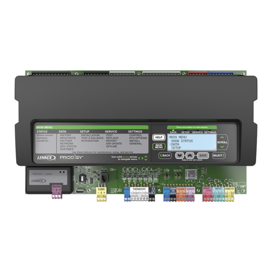
20. M3 Unit Controller Inputs and Outputs Figure 31. Wiring Diagram Page 85... - Page 86 Appendix A. M3 User Interface Menu Structure, Display Status Screen and LED Operation Indications Level 1 Menu Options SELECT BACK ALARMS, ZAT, DAT, SCROLL OCC OR UNOCC, DEMAND STATUS ALARMS SHOW STATUS PRESENT? ZAT, DAT, OCC DATA OR UNOCC, DEMAND SETUP STATUS SERVICE...
- Page 87 Menu Interface Details The following tables indicate the major levels of the menu interface. Many of these options have more levels which are described in the following sections that detail DATA, SETUP, SERVICE, and SETTINGS. Use the SELECT button to progress to the next menu level (i.e. level 1 to level 2). Use the SCROLL arrows ▲▼...
- Page 88 Table 57. Menu Interface (Level 1 - DATA) Level 2 Level 3 Level 4 Level 5 CURRENT ALARMS ACTIVE ALARMS XXX APP MODE ADVANCED BLOWER SPEED X % AND RPM IF A BLOWER BLOWER STATUS STATUS BOX. TARGET: X % DAMPER DAMPER STATUS ACTUAL X %...
- Page 89 Table 58. Menu Interface (Level 1 - SETUP) Level 2 Level 3 Level 4 Level 5 Level 6 LANGUAGE = = ENGLISH, ESPANOL, OR FRANCAIS DATE/TIME = = DAY, MONTH, YEAR, HOURS, MINUTES, SECONDS DISPLAY UNITS F/C = FAHRENHEIT OR CELSIUS MODEL NUMBER = LOCATED ON UNIT NAMEPLATE.
- Page 90 Table 58. Menu Interface (Level 1 - SETUP) Level 2 Level 3 Level 4 Level 5 Level 6 • NETWORK SENSOR CO2 = YES OR NO • NETWORK SENSOR RELATIVE HUMIDITY = YES OR NO • NETWORK SENSOR TEMPERATURE = YES OR NO •...
- Page 91 Table 59. Menu Interface (Level 1 - SERVICE) Note: Available menu options are dependent on hardware configuration. Use the Adjust and set values WHEN SELECTED (PRESS BACK TO RETURN TO Level 1 Level 2 Level 3 arrows to scroll up or down for THE PREVIOUS MENU) selection options.
- Page 92 Table 59. Menu Interface (Level 1 - SERVICE) Note: Available menu options are dependent on hardware configuration. Use the Adjust and set values WHEN SELECTED (PRESS BACK TO RETURN TO Level 1 Level 2 Level 3 arrows to scroll up or down for THE PREVIOUS MENU) selection options.
- Page 93 Table 60. Menu Interface (Level 1 - SETTINGS) Note: Available menu options are dependent on hardware configuration. USE THE ADJUST AND SET VALUES AR Level 2 Level 3 Level 4 Level 5 ROWS TO SCROLL UP OR DOWN FOR SE LECTION OPTIONS.
- Page 94 Table 60. Menu Interface (Level 1 - SETTINGS) Note: Available menu options are dependent on hardware configuration. USE THE ADJUST AND SET VALUES AR Level 2 Level 3 Level 4 Level 5 ROWS TO SCROLL UP OR DOWN FOR SE LECTION OPTIONS.
- Page 95 System Status Screen System Status Screen Table 61. Network Status The display shows operating mode if in normal operation. Screen Label Network Type Alarms will interrupt the display. LonTalk Alarm messages will appear on the display and remain there BACNET BACnet until dismissed.
- Page 96 Normal Mode Messages The format of the message is mode and setpoint (see table 62). Table 62. Possible MODE messages COMP LOAD Unit is running at lower power capacity SHEDDING COOLING Cool demand present; unit is in mechanical cooling. DEHUMIDIFICATION Unit is dehumidifying FREE COOLING Cooling demand is present, no compressor cooling.
- Page 97 LED Operations LED Indicators: Some indicators on the circuit board are visible with the cover in place; others are not. The indicators and their meanings are described in table 63. Table 63. LED Operation Indications Status Indication Meaning Green Slow Flash Normal Operation Green Fast Flash...
- Page 98 Appendix B. Model Number and Configuration ID 1 / 2 Settings This section addresses the requirement that specific configuration information must be completed using the SETUP / INSTALL feature if a new unit controller was being installed. Other requirements are the addition of accessories that were not factory-installed.
- Page 99 Power Exhaust Control [4] B = BACnet Not Installed = N L = LonTalk (Lennox) Damper Position = A NOTE - The M3 unit controller will display applicable alarm(s) if any positions is left unconfigured (U). Figure 35. Configuration ID 1...
- Page 100 Installed on DI-3 = 3 [5] Phase / Voltage Detection* N = Not Installed 1 = Enabled Internal (Lennox) 2 = External (A42) Phase Detection on * When Phase / Voltage detection monitoring is enabled on three-phase system and DI-2 configured incorrectly will cause the system to go to demand hold and restart after 3 minutes.
- Page 101 Appendix C. Control Parameter Definitions Many M3 unit controller operations may be modified within a set range. Default settings are based on common or average applications; change parameter settings only when custom applications, preferences or local building codes exist. Default, minimum, and maximum range settings are found in table 64. NOTICE: Units with Novar 2051 module! Failure to perform the following steps may result in unsatisfactory unit operation.
- Page 102 Table 64. M3 Control Parameters Control Parameter Control Value Screen Name Parameter Short Description Min. Default Max. Units Description = ENGLISH, ESPA Select desired language for user interface. Options are English, LANGUAGE LANGUAGE (SPANISH) or FRAN Option French and Spanish. (FRENCH) Power and Damper Parameters Applicable to A Box units only.
- Page 103 Table 64. M3 Control Parameters Control Parameter Control Value Screen Name Parameter Short Description Min. Default Max. Units Units Description Description Blower Proportional Base Control Loop for Variable Air Variable Air Volume or Constant Air Volume with Bypass Damper BLOWER PID P CONST Counts Volume or Constant Air Volume supply PID Proportional constant.
- Page 104 Table 64. M3 Control Parameters Control Parameter Control Value Screen Name Parameter Short Description Min. Default Max. Units Units Description Description Constant Air Volume with Bypass Damper Manual Reset Constant air volume with bypass damper manual reset value output. BLOWER MANUAL RESET 20.0 52.0 100.0...
- Page 105 Table 64. M3 Control Parameters Control Parameter Control Value Screen Name Parameter Short Description Min. Default Max. Units Units Description Description Gas Minimum Low Fire Time HT GAS HI FIRE DLAY Seconds The minimum low fire time before high fire is allowed. Prior to High Fire HT GAS OFF DELAY Heating Off Delay Timer...
- Page 106 Table 64. M3 Control Parameters Control Parameter Control Value Screen Name Parameter Short Description Min. Default Max. Units Units Description Description • Low ambient outdoor air limit temp. 2. Parameters 83 and 84 are used to shed fans. Low Ambient Outdoor Air Limit •...
- Page 107 Table 64. M3 Control Parameters Control Parameter Control Value Screen Name Parameter Short Description Min. Default Max. Units Units Description Description • Stage 4 stage up timer. The maximum time that cooling stage 3 runs before calling cooling stage 4. Maximum Stage 3 Cooling Time CL STG 4 STGUP TIME 3600...
- Page 108 Table 64. M3 Control Parameters Control Parameter Control Value Screen Name Parameter Short Description Min. Default Max. Units Units Description Description Block 5 Miscellaneous Parameters Smoke alarm control options. Smoke alarm control options. Unit off. Blower on, exhaust fan off, outdoor air damper open (positive pressure) Blower on, exhaust fan on, outdoor air damper closed (negative pressure).
- Page 109 Table 64. M3 Control Parameters Control Parameter Control Value Screen Name Parameter Short Description Min. Default Max. Units Units Description Description • Enables return air temperature limit option. Enable Return Air Temperature EN RET AIR TMP LMT Option • Return air limits may be used for limiting zone temperatures. Con Limit tinuous fan operation recommended.
- Page 110 Table 64. M3 Control Parameters Control Parameter Control Value Screen Name Parameter Short Description Min. Default Max. Units Units Description Description • Suspends all unit operation room sensor and Constant Air Volume with bypass damper applications. • Suspends Fresh Air Heat Control-Reheat, Fresh Air Cooling Con ZONE SENS STRTUP DLY Room Sensor Start-up Delay Minutes...
- Page 111 Table 64. M3 Control Parameters Control Parameter Control Value Screen Name Parameter Short Description Min. Default Max. Units Units Description Description • Heating dead-band. Used only with M3 unit controller room sensor applications. HEAT STAGE DEADBAND Heat Stage Deadband 1.00 1.00 3.75 °F...
- Page 112 Table 64. M3 Control Parameters Control Parameter Control Value Screen Name Parameter Short Description Min. Default Max. Units Units Description Description • Minimum autochangeover dead-band temperature. Dead band must be greater than or equal to Parameter 142 plus Parameter Automatic Changeover AUTO CHGOVR DEADBND 2.00 3.00...
- Page 113 Table 64. M3 Control Parameters Control Parameter Control Value Screen Name Parameter Short Description Min. Default Max. Units Units Description Description These are the operating profile options for the economizer damper during free cooling when any compressor is on and can be selected as follows: Option 0: Damper continues to modulate while compressors are on, but the effect of mechanical cooling may force the damper closed to...
- Page 114 Table 64. M3 Control Parameters Control Parameter Control Value Screen Name Parameter Short Description Min. Default Max. Units Units Description Description Fresh Air Cooling Control Cycle FAC MIN CYCLE TIME 1800 Seconds Fresh Air Cooling minimum cycle time. Time • Fresh Air Cooling stage differential between stages.
- Page 115 Table 64. M3 Control Parameters Control Parameter Control Value Screen Name Parameter Short Description Min. Default Max. Units Units Description Description A55 Service Output Control Mode = X + 32*Y + 16*Z Input source = X: None. Standard Service Output based on alarms. Compressor 1 duty cycle.
- Page 116 Table 64. M3 Control Parameters Control Parameter Control Value Screen Name Parameter Short Description Min. Default Max. Units Units Description Description Service Output Deadband for SRV OUTPT DB TEMP 162.0 °F Service Output Deadband for Temperature Temperature SRV OUTPT DELAY Service Output Delay 8160 Seconds...
- Page 117 Table 64. M3 Control Parameters Control Parameter Control Value Screen Name Parameter Short Description Min. Default Max. Units Units Description Description Discharge Air Control Heating DACH OAT RS PRP BND Outdoor Air Temperature Reset 20.0 60.0 °F Discharge Air Control Heating temperature reset proportional band. Proportional Band Discharge Air Control Heating Return Air Temperature...
- Page 118 Table 64. M3 Control Parameters Control Parameter Control Value Screen Name Parameter Short Description Min. Default Max. Units Units Description Description Advance Airflow No Airflow NO AIRFLOW ALARM EU Count Applicable to A Box units only. Alarm Evaluation OUTDOOR AIR TARGET Outdoor Air Target 1000 Applicable to A Box units only.
- Page 119 Description Description Note: Options for Parameter 287 are not accessible via the M3 Unit Controller user interface. Options can be set using the Lennox UC software. Default set bit is 0x00000300. Set Bit Description 0x00000002 Enable Fresh Air Heating (ALGO_FAH)
- Page 120 Appendix D. Parameter Cross-References M2 ECTO to M3 Parameter Table 65. M2 ECTO to M3 Parameter Cross-Reference Accessible via ECTO M3 Parameter M3 Parameter Name Settings Menu 0.01 DIN_Supply_VAV_Control_Mode 0.02 DIN_MSAV_SMK_Stg_Output 0.03 DIN_MSAV_VT_Stg_Output 0.04 DIN_MSAV_HT_Stg_Output 0.05 DIN_MSAV_CL_Stg_1_Output 0.06 DIN_MSAV_Min_Output_for_CL_VT_SMK 0.07 DIN_MSAV_Min_Output_for_HT 0.08 DIN_CAVB_ManualReset...
- Page 121 Table 65. M2 ECTO to M3 Parameter Cross-Reference Accessible via ECTO M3 Parameter M3 Parameter Name Settings Menu 1.16 NONE 1.17 NONE 1.18 DIN_HT_Pump_SuppHTStage1Dif f 1 1.19 DIN_HT_Pump_SuppHTStage1Dif f 2 1.20 DIN_HT_Pump_SuppHTStageLatch1 1.21 DIN_HT_Pump_SuppHTStageLatch2 1.22 DIN_HT_Pump_SuppHTStageUpT imer1 1.23 DIN_HT_Pump_SuppHTStageUpT imer2 1.24 DIN_HT_Pump_StageDownT imer 1.25...
- Page 122 Table 65. M2 ECTO to M3 Parameter Cross-Reference Accessible via ECTO M3 Parameter M3 Parameter Name Settings Menu 4.02 DIN_CL_BL_On_Delay 4.03 DIN_CL_BL_Off_Delay 4.04 DIN_Max_Frz_Stat_Occurrences 4.05 DIN_Cond_Fan_ReStart_Delay 4.06 DIN_LAC_SP_T emp_1 4.07 DIN_LAC_SP_T emp_2 4.08 DIN_Compr_1_Low_T emp_Lockout 4.09 DIN_Compr_2_Low_T emp_Lockout 4.10 DIN_Compr_3_Low_T emp_Lockout 4.11 DIN_Compr_4_Low_T emp_Lockout 4.12...
- Page 123 Table 65. M2 ECTO to M3 Parameter Cross-Reference Accessible via ECTO M3 Parameter M3 Parameter Name Settings Menu 5.18 DIN_DCV_Damper_Full_Open_SP 5.19 DIN_DCV_Low_T emp_Override_Full_Closed 5.20 DIN_DCV_Low_T emp_Override_Start_Closing 5.21 DIN_DCV_High_T emp_Override_Start_Closing 5.22 DIN_DCV_High_T emp_Override_Full_Closed 5.23 DIN_Free_CL_Max_Damper 5.24 DIN_Min_Damper_Position 5.25 DIN_Zone_Sensor_StartUp_Delay 5.26 DIN_IAQ_Input_Mode 5.27 NONE 6.01...
- Page 124 Table 65. M2 ECTO to M3 Parameter Cross-Reference Accessible via ECTO M3 Parameter M3 Parameter Name Settings Menu 7.07 DIN_FAC_StageDeadband 7.08 DIN_FAC_MinCycleTime 7.09 DIN_FAC_StageDifferential 7.10 DIN_DACH_OCP_SP 7.11 DIN_DACH_UnOCP_SP 7.12 DIN_DACH_StageDeadband 7.13 DIN_DACH_FAH_StageUpTimer 7.14 DIN_DACH_FAH_StageDownTimer 7.15 DIN_DACH_StageDifferential 7.16 DIN_DACC_OCP_SP 7.17 DIN_DACC_UnOCP_SP 7.18 DIN_DACC_StageDeadband 7.19...
- Page 125 Table 65. M2 ECTO to M3 Parameter Cross-Reference Accessible via ECTO M3 Parameter M3 Parameter Name Settings Menu 8.24 DIN_Exh_Fan_Stage2_Damper_DB 8.26 DIN_Exh_Fan_StageUp_Delay 9.01 NONE 9.02 DIN_OAC_SetPoint 9.03 NONE 9.04 NONE 9.05 NONE 9.06 NONE 9.07 NONE 9.08 DIN_OAC_ManualReset 9.09 NONE 9.10 NONE 9.11...
- Page 126 Table 65. M2 ECTO to M3 Parameter Cross-Reference Accessible via ECTO M3 Parameter M3 Parameter Name Settings Menu 10.17 DIN_EP_PARAM_OD_CFM_TARGET 10.18 DIN_EP_PARAM_OD_CFM_CALIB 10.19 DIN_EP_PARAM_LO_OD_CFM_ALARM_STPT 10.20 DIN_EP_PARAM_HI_OD_CFM_ALARM_STPT 10.21 DIN_EP_PARAM_MAX_OD_CFM_DCV_STPT 10.22 DIN_EP_PARAM_MAX_OD_CFM_FC_STPT 10.23 DIN_EP_PARAM_LO_OD_CFM_ALARM_EV AL 10.24 DIN_EP_PARAM_HI_OD_CFM_ALARM_EV AL 10.25 DIN_EP_PARAM_OA_DMPR_ERR_ALARM_EV AL 10.26 DIN_EP_PARAM_ALTITUDE_STPT 10.27 DIN_EP_PARAM_BLOW_RAMP_RA TE_STPT...
- Page 127 Table 65. M3 Parameter to M2 ECTO Cross-Reference Accessible via M3 Parameter ECTO Parameter Name Settings Menu NONE DIN_PwrExh_Stg2_Min_Blower_Output 0.10 DIN_VAV_CAVB_PID_P_Constant 0.11 DIN_VAV_CAVB_PID_I_Constant 0.12 DIN_VAV_CAVB_PID_D_Constant NONE DIN_CAVB_Static_Pressure_SMK_SP NONE DIN_CAVB_Static_Pressure_VT_SP NONE DIN_CAVB_Static_Pressure_HT_SP NONE DIN_CAVB_Static_Pressure_CL_SP 0.17 DIN_CAVB_Min_Output_for_CL_VT_SMK 0.18 DIN_CAVB_Min_Output_for_HT 0.19 DIN_CAVB_Max_Output 0.08 DIN_CAVB_ManualReset 0.21 DIN_Static_Shutdown_SP...
- Page 128 Table 65. M3 Parameter to M2 ECTO Cross-Reference Accessible via M3 Parameter ECTO Parameter Name Settings Menu 3.09 DIN_HT_Gas_MAX_GV_Sense_Occurrences 3.11 DIN_HT_Gas_StageUpTimer 3.12 DIN_HT_Gas_StageDownT imer 3.13 DIN_HT_Gas_MVG_Mode 3.14 DIN_HT_Gas_MVG_StartupPhase2Delay 4.01 DIN_CoolDownDelay 4.02 DIN_CL_BL_On_Delay 4.03 DIN_CL_BL_Off_Delay 4.04 DIN_Max_Frz_Stat_Occurrences 4.05 DIN_Cond_Fan_ReStart_Delay 4.06 DIN_LAC_SP_T emp_1 4.07 DIN_LAC_SP_T emp_2 4.08...
- Page 129 Table 65. M3 Parameter to M2 ECTO Cross-Reference Accessible via M3 Parameter ECTO Parameter Name Settings Menu 5.08 DIN_Max_Phase_Monitor_Occurences 5.16 DIN_DCV_Max_Damper_Open 5.17 DIN_DCV_Damper_Start_Open_SP 5.18 DIN_DCV_Damper_Full_Open_SP 5.22 DIN_DCV_High_T emp_Override_Full_Closed 5.21 DIN_DCV_High_T emp_Override_Start_Closing 5.19 DIN_DCV_Low_T emp_Override_Full_Closed 5.20 DIN_DCV_Low_T emp_Override_Start_Closing NONE DIN_OAC_Damper_Start_Open_SP NONE DIN_OAC_Damper_Full_Open_SP 9.02 DIN_OAC_SetPoint...
- Page 130 Table 65. M3 Parameter to M2 ECTO Cross-Reference Accessible via M3 Parameter ECTO Parameter Name Settings Menu 6.23 DIN_Free_Cooling_Supply_SP 6.26 DIN_Economizer_Free_Cooling_T emp_SP NONE DIN_Economizer_Free_Cooling_T emp_Offset NONE DIN_Economizer_Free_Cooling_Enth_SP NONE DIN_Economizer_Free_Cooling_Enth_Of fset 6.27 DIN_EconomizerProfile 7.01 DIN_FAH_StageDifferential 7.02 DIN_FAH_Reheat_OAT_SP 7.03 DIN_FAH_Reheat_Damper 7.04 DIN_FAH_Reheat_SP 7.05 DIN_FAT_AutoChangeOverDelay 7.06...
- Page 131 Table 65. M3 Parameter to M2 ECTO Cross-Reference Accessible via M3 Parameter ECTO Parameter Name Settings Menu 8.05 DIN_DACC_OAT_RS_SP 8.06 DIN_DACC_OAT_RS_Proportional_Band 8.04 DIN_DACC_RAT_RS_Adjust_Band 8.02 DIN_DACC_RAT_RS_SP 8.03 DIN_DACC_RAT_RS_Proportional_Band 8.01 DIN_DACC_RS_Limit 8.14 DIN_DACH_OAT_RS_Adjust_Band 8.12 DIN_DACH_OAT_RS_SP 8.13 DIN_DACH_OAT_RS_Proportional_Band 8.04 DIN_DACH_RAT_RS_Adjust_Band 8.09 DIN_DACH_RAT_RS_SP 8.10 DIN_DACH_RAT_RS_Proportional_Band 8.08 DIN_DACH_RS_Limit...
- Page 132 Table 65. M3 Parameter to M2 ECTO Cross-Reference Accessible via M3 Parameter ECTO Parameter Name Settings Menu DIN_EP_PARAM_OA_DMPR_ERR_ALARM_EVAL 10.25 DIN_EP_PARAM_ALTITUDE_STPT 10.26 DIN_EP_PARAM_BLOW_RAMP_RATE_STPT 10.27 NONE DIN_EP_Calibration_String1 NONE DIN_EP_Calibration_String2 NONE DIN_BACnet_Max_Info_Frames NONE DIN_BACnet_Max_Master NONE DIN_BACnet_Device_Name NONE DIN_BACnet_Device_Description NONE DIN_BACnet_Device_Location NONE DIN_BACnet_Database_Revision NONE DIN_BACnet_Device_id NONE DIN_BACnet_Device_id_source...
- Page 133 Table 65. M3 Parameter to M2 ECTO Cross-Reference Accessible via M3 Parameter ECTO Parameter Name Settings Menu NONE DIN_CSSH_CCH_On_Limit NONE DIN_CCH_HighAmb_T emp NONE DIN_CCH_LowAmb_T emp NONE DIN_CSSH_Formula_Coef f 1 NONE DIN_CSSH_Formula_Coef f 2 NONE DIN_CSSH_Formula_Of f set NONE DIN_CSSH_Stability_TimeDelay NONE DIN_MAX_Low_CSSH_Count NONE DIN_Comp_Sump_T emp_Rise_TimeDelay...
- Page 134 Table 65. M3 Parameter to M2 ECTO Cross-Reference Accessible via M3 Parameter ECTO Parameter Name Settings Menu NONE 2.09 NONE 3.08 NONE 3.10 NONE 3.15 NONE 3.16 NONE 3.17 NONE 3.18 NONE 3.19 NONE 3.20 NONE 3.21 NONE 3.22 NONE 3.23 NONE 4.16...
- Page 135 Table 65. M3 Parameter to M2 ECTO Cross-Reference Accessible via M3 Parameter ECTO Parameter Name Settings Menu NONE 9.16 NONE 9.17 NONE 9.18 NONE 9.19 NONE 9.20 NONE 9.21 NONE 9.22 NONE 9.23 NONE 9.24 NONE 9.25 NONE 10.03 NONE 10.04 NONE 10.10...
- Page 136 Appendix E. Prodigy 2.0 Events and Alarms Phase - Voltage Detection The M3 unit controller has the ability to detect that the rooftop unit power source has the correct frequency, phasing and voltage levels. When this feature is enabled, the detection of frequency and phasing is determined at power-on and the voltage level is continuously monitored. If any of these is out of range, then an alarm is logged and the rooftop unit operation is locked out.
- Page 137 M3 Event Codes TABLE 66. PRODIGY 2.0 ALARM CODES ALARM TYPE CODES DISPLAY MESSAGE Event Action Check power connections. The unit controller will set an alarm Erratic Power whenever service is turned off due to detection of power loss. User will...
- Page 138 TABLE 66. PRODIGY 2.0 ALARM CODES ALARM ALARM TYPE TYPE CODES CODES DISPLAY MESSAGE Event Action Compressor is off. Check charge, fans and coil. The unit controller will clear High pressure Switch alarm when corresponding High Pressure Switch is detected as closed.
- Page 139 TABLE 66. PRODIGY 2.0 ALARM CODES ALARM ALARM TYPE TYPE CODES CODES DISPLAY MESSAGE Event Action Check for block drain, condensate lines and drain pan overflow switch. Alarm set if overflow switch is detected opened and compressor will be locked out. system will automatically clear alarm...
- Page 140 TABLE 66. PRODIGY 2.0 ALARM CODES ALARM ALARM TYPE TYPE CODES CODES DISPLAY MESSAGE Event Action ALARM HEAT 1 CAI SWITCH S18 Check heat section 1 combustion air motor and proof switch. ALARM STRIKE 3 HEAT 1 CAI SWITCH S18 Check heat section 1 combustion air motor and proof switch.
- Page 141 TABLE 66. PRODIGY 2.0 ALARM CODES ALARM ALARM TYPE TYPE CODES CODES DISPLAY MESSAGE Event Action if measurement of the return air temperature sensor is out of specified range (including open / short detection, the alarm will be activated. alarm will automatically clear once in range condition is detected.
- Page 142 TABLE 66. PRODIGY 2.0 ALARM CODES ALARM ALARM TYPE TYPE CODES CODES DISPLAY MESSAGE Event Action ALARM OUTDOOR ECON SENSOR A24 Check sensor and wiring. ALARM AIR VOL CONTROL SETUP ERROR Check for proper installation of GP board and settings.
- Page 143 TABLE 66. PRODIGY 2.0 ALARM CODES ALARM ALARM TYPE TYPE CODES CODES DISPLAY MESSAGE Event Action High output voltage on T1 transformer. alarm set when 24VAC voltage high if calculated RMS voltage is below low voltage alarm threshold for more than two seconds. System will stop unit operations (cooling, heating and ventilation). Low voltage threshold is 30VAC.
- Page 144 TABLE 66. PRODIGY 2.0 ALARM CODES ALARM ALARM TYPE TYPE CODES CODES DISPLAY MESSAGE Event Action ADVANCE AIRFLOW DAMPER PRESSURE ALARM Outdoor air differential pressure sensor value not in valid range. Might be tubing problem or high return duct resistance.
- Page 145 TABLE 66. PRODIGY 2.0 ALARM CODES ALARM ALARM TYPE TYPE CODES CODES DISPLAY MESSAGE Event Action Prodigy provides 0-5VDC analog input for the suction pressure sensor. Sensor output is connected to P333, pin 1. valid suction pressure range is 0 to 300 psig.
- Page 146 Appendix F. M3 Unit Controller I/O Interfaces Table 67. M3 Unit Controller Signal Reference Diagram 24VAC 24 VAC COM S - BUS P297 P298 P299 MS 9413-03-401 MS 9413-10-407 MS 9413-10-408 MS 9413-10-409 Pin # Label Description Type Description Part Number P297 Thermostat Assembly MS 9413-10-407...
- Page 147 Figure 37. M3 Unit Controller...
- Page 148 Appendix G. Abbreviations M3 board. Main RTU control board A169 MCB1 board. A Box motor control board. Analog input Analog output Blower Add on board for third and forth compressor and second-stage heat (A178). 1st stage cooling 2nd stage cooling 3rd stage cooling 4th stage cooling Combustion air inducer...
- Page 149 RT16 Return air temperature sensor RT17 Outdoor air temperature sensor Smoke detection mode (alarm) Setpoint Stage Terminal block UnOCP Unoccupied Thermostat demand, heat stage 1 Thermostat demand, heat stage 2 Thermostat demand, heat stage 3 Thermostat demand, heat stage 4 Alternating current voltage Variable air volume.
Need help?
Do you have a question about the Prodigy 2.0 and is the answer not in the manual?
Questions and answers