
Related Manuals for Lennox Climatic 200


Summary of Contents for Lennox Climatic 200
- Page 1 INSTALLATION OPERATING & MAINTENANCE MANUAL x 1000 MODE ON/OFF mode on off ECOLEAN CLIMATIC™ 200/400 English/01-2004...
-
Page 3: Table Of Contents
INDEX CONTENTS PAGE • INDEX • GENERAL DESCRIPTION ® • THE KEYPAD, Climatic ® • THE KEYPAD, Climatic ® • THE KEYPAD REMOTE CONTROLLER (OPTION), RC Climatic ® • THE KEYPAD REMOTE CONTROLLER (OPTION), RC Climatic • FUNCTION UNIT COMMISSIONING SELECTING OPERATING MODE SELECTING SET POINT •... -
Page 4: General Description
GENERAL DESCRIPTION This equipment is an electronic device that controls packaged water cooling systems via air and reversible air/water heat pumps. The thermostat allows the following operations: - Unit ON/OFF. - Select system operating mode. - Set point adjustment. - Alarm signal relay. - Display temperature. -
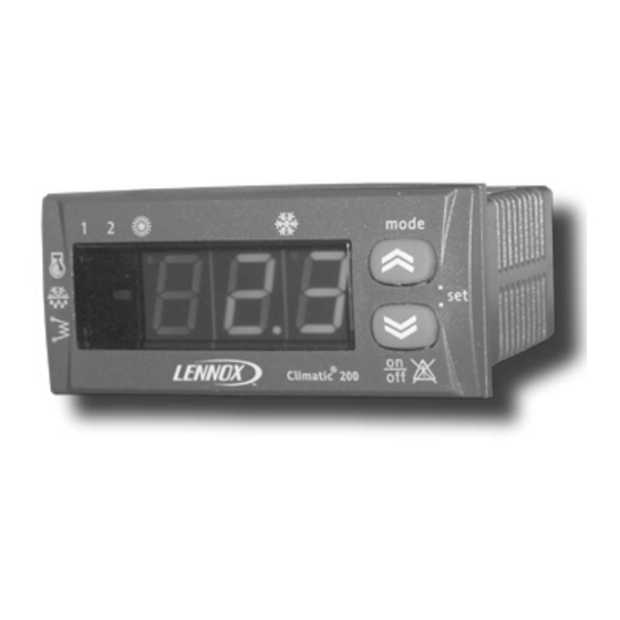
Page 5: The Keypad, Climatic ® 200
® THE KEYPAD INCORPORATED AT THE UNIT, MODEL Climatic READING DISPLAY This is a 3-digit display, the inlet water temperature is shown in degrees (default), ºC (when shows decimal point), or ºF (without the decimal point). The following can also be displayed: - Values of all parameters controlled by the equipment: - Cooling set point, cooling differential temperature. -
Page 6: The Keypad, Climatic ® 400
® THE KEYPAD INCORPORATED AT THE UNIT, MODEL Climatic READING DISPLAY This is a 3-digit display, the inlet water temperature is shown in degrees (default), ºC (when shows decimal point), or ºF (without the decimal point). The following can also be displayed: - Values of all parameters controlled by the equipment: - Cooling set point, cooling differential temperature. -
Page 7: The Keypad Remote Controller (Option), Rc Climatic ® 200
® THE KEYPAD REMOTE CONTROLLER (OPTION), MODEL RC Climatic READING DISPLAY This is a 3-digit display, the inlet water temperature is shown in degrees (default), ºC (when shows decimal point), or ºF (without the decimal point). The following can also be displayed: - Values of all parameters controlled by the equipment: - Cooling set point, cooling differential temperature. -
Page 8: The Keypad Remote Controller (Option), Rc Climatic ® 400
® THE KEYPAD REMOTE CONTROLLER (OPTION), MODEL RC Climatic READING DISPLAY This is a 3-digit display, the inlet water temperature is shown in degrees (default), ºC (when shows decimal point), or ºF (without the decimal point). The following can also be displayed: - Values of all parameters controlled by the equipment: - Cooling set point, cooling differential temperature. -
Page 9: Function
FUNCTION UNIT COMMISSIONING When all the instructions in the Operating, Service and Installation Manual have been carried out, the unit can be commissioned as follows: POWER SUPPLY TO THE UNIT - Set the general cut-off switch to ON. TURN ON/OFF THE UNIT - Pressing on off button during more than 2 seconds lets you turn ON the unit. -
Page 10: Menu Mode
MENU MODE Press buttons and release within 2 seconds, to enable the user mode on off to get to the menu mode mode mode To move through the menu on this way Press buttons simultaneously and release within 2 seconds. mode on off on off... -
Page 11: Adjusting Water Temperature (Set Point)
SET POINT THERMOSTAT FUNCTION DESCRIPTION LEVEL 1 LEVEL 2 LEVEL 3 MAIN DISPLAY Set point value Cooling set point Visualizes: SET POINT Inlet water temperature Active alarms Set point value Heating set point See page 7, for adjustment of set point of the system. The water temperature is thermostatically controlled via a set point and a tolerance range (differential). -
Page 12: Analogue Inputs, Temperature Probes
ANALOGUE INPUTS MAIN DISPLAY Visualizes: SET POINT Probe value Inlet water temperature mode Active alarms Press Press Probe value on off Probe status Probe value Probe value Probe value NOTE: When the leds on the mode mode display lit alternatively from one to the other, you are on on off on off... -
Page 13: Options
OPTIONS ON/OFF REMOTE Remove the wire between 93 and 94 terminal block on the electrical box and insert a contact. If the unit stops with ON/OFF Remote, "E00" will appear on the unit display. REMOTE CHANGEOVER SUMMER/WINTER On heat pump units, it is possible to select cooling or heating mode with a remote contact. The ON/OFF remote can be combined with this function in order to control the unit from a long distance, with the Off/Cool/Heat options. -
Page 14: Options
OPTIONS Set point ºC Set point ºC DYNAMIC SET POINT 42ºC 12ºC heating set point 38ºC 9ºC cooling set point Outdoor temp. ºC Outdoor temp. ºC 6ºC 12ºC 25ºC 35ºC starting starting differential differential Dynamic Dynamic set point set point -10ºC 6ºC COOLING MODE... - Page 15 MODIFY PARAMETERS MAIN DISPLAY mode Press on off Visualizes: Inlet water temperature Active alarms Press Press mode Press Press on off PARAMETERS NOTE: When the leds on the mode mode display lit alternatively from one to the other, you are on on off on off menu mode.
-
Page 16: Modify Unit Parameters
MODIFY UNIT PARAMETERS DESCRIPTION MIN MAX UNIT VAR. ® 1 CIRCUIT UNIT MODEL Climatic Cooling thermal regulator hysteresis 25,5 ºC 25,5 ºC Heating thermal regulator hysteresis Steps delta 25,5 ºC St4 configuration 0: no probe / 2: remote changeover S./W. / 3: outdoor temp. St4 configuration (if digital) 3: remote changeover Summer/Winter. -
Page 17: Operating Hours
OPERATING HOURS mode Press on off Visualizes: Inlet water temperature Press Active alarms Press Press Press Compressor 1 operating hours Compressor 2 operating hours mode Press Press Compressor 3 operating hours on off Compressor 4 operating hours OPERATING HOURS Water pump operating hours NOTE: When the leds on the mode mode... -
Page 18: Alarm Codes
ALARM CODES MENU STRUCTURE MAIN DISPLAY LEVEL 1 Visualizes: SET POINT Inlet water temperature Active alarms Press Probe status mode Press LEVEL 2 Press on off Active alarms Codes ALARMS ----- The unit self-protects through safety devices; when any of these safety devices detect an anomaly, this is shown in the display in order to advise the installer. - Page 19 ALARM CODES EFFECT VIS. DESCRIPTION ACTION Press the ON/OFF button until the alarm Anti-freeze alarm. disappears; if alarm shows up again, It indicates the outlet water temperature is lower • Check the water filter. than +3ºC. Unit stops • Check water flow. After 1 automatic reset, it comes to be a manual •...
-
Page 20: Alarm Codes
ALARM CODES VIS. DESCRIPTION EFFECT ACTION Press the ON/OFF button until the alarm disappears; if alarm shows up again, check Compressor thermal protection alarm Compressor 1 continuity and change the faulty component. compressor 1 circuit 2: circuit 2 • Check refrigerant charge. - Compressor thermal protection open. -
Page 21: Defrosting System
DESCRIPTION OF THE DEFROSTING SYSTEM The defrosting process is activated during heating mode in heat pump units, when the outside temperature is low and the outdoor coil could become frozen. To melt the ice the defrosting function will switch the unit to cooling operation for a short period. During defrosting mode the low pressure is at minimum level, consequently the pressure switch is disabled in this mode. -
Page 22: Fan Speed Control (Only For 0091 To 0812 Units)
FAN SPEED CONTROL (only for 0091 to 0812 units) Fan speed control: Management of the fan speed It is managed by a fan speed control printed plate located at the electrical box of the unit. The function of this fan speed control is to prevent from very low condensing temperatures during the cooling mode in order to operate between -5ºC and 46ºC (outside temperature). -
Page 23: Safety Devices
SAFETY DEVICES These units contain various safety devices, in order to avoid the water reaches low temperatures so it may cause a damage to the system. 1.- Anti-freeze protection. This protection is activated by the control of the unit when the outlet water temperature probe (St2), located inside the water exchanger, measures +5ºC and deactivates when the outlet water temperature probe reaches to +6ºC again. - Page 26 : marketing@lennoxdist.com www.lennoxeurope.com CLIMATIC™ 200/400 Due to Lennox's ongoing commitment to quality, Specifications, Ratings and Dimensions subject to change without notice and without incurring liability. Improper installation, adjustment, alteration, service or maintenance can cause property damage or personal injury. MIL28E-0104/01-2004...
Need help?
Do you have a question about the Climatic 200 and is the answer not in the manual?
Questions and answers