Table of Contents
Advertisement
Improper installation, adjustment, alteration, service or maintenance can cause property damage, personal injury or
loss of life.
Installation and service must be performed by a licensed professional HVAC installer (or equivalent) or service agency.
1.1.
. . . . . . . . . . . . . . . . . . . . . . . . . . . . . . . . . . . . . . . . . . . . . . . . . . . . . . . . . . . . . . . . . . . . . . . . .
1.2.
1.3.
2.1.
2.1.1.
2.1.2.
2.2.
2.2.1.
2.2.2.
2.2.3.
2.2.4.
2.2.5.
2.2.5.1.
2.2.5.2.
2.2.5.3.
2.2.5.4.
3.1.
3.1.1.
3.1.1.1.
3.1.1.2.
3.1.2.
3.1.3.
3.1.4.
3.1.4.1.
3.1.4.2.
3.1.4.3.
3.1.5.
3.1.5.1.
3.1.5.2.
WARNING
Table Of Contents
. . . . . . . . . . . . . . . . . . . . . . . . . . . . . . . . . . . . . . . . . . . . . . .
. . . . . . . . . . . . . . . . . . . . . . . . . . . . . . . . . . . . . . . . . . . . . . . . . . . . . . . . . . . . . . . . . .
. . . . . . . . . . . . . . . . . . . . . . . . . . . . . . . . . . . . . . . . . . . . . . . . . . . . . . . . . . . . . . . . .
. . . . . . . . . . . . . . . . . . . . . . . . . . . . . . . . . . . . . . . . . . . . . . . . . . . . . . . . . . .
. . . . . . . . . . . . . . . . . . . . . . . . . . . . . . . . . . . . . . . . . . . . . . . . . . . . . . . . . . . .
. . . . . . . . . . . . . . . . . . . . . . . . . . . . . . . . . . . . . . . . . . . . . . . . . . . . . . . . . . . .
. . . . . . . . . . . . . . . . . . . . . . . . . . . . . . . . . . . . . . . . . . . . . . . . . . . . . .
. . . . . . . . . . . . . . . . . . . . . . . . . . . . . . . . . . . . . . . . . . . . . . .
. . . . . . . . . . . . . . . . . . . . . . . . . . . . . . . . . . . . . . . . . . . . . . . . . . . . . . . . . . . . . . . .
. . . . . . . . . . . . . . . . . . . . . . . . . . . . . . . . . . . . . . . . . . . . . . . . . . .
. . . . . . . . . . . . . . . . . . . . . . . . . . . . . . . . . . . . . . . . . . . . . . . . . . . . . .
. . . . . . . . . . . . . . . . . . . . . . . . . . . . . . . . . . . . . . . . . . . . . . . . . .
(M3 UNIT CONTROLLER)
APPLICATION GUIDE
. . . . . . . . . . . . . . . . . . . . . . . . . . . . . . . . . . . . . . . . . . . .
. . . . . . . . . . . . . . . . . . . . . . . . . . . . . . . . . .
. . . . . . . . . . . . . . . . . . . . . . . . . . . . . . . . . . . . . .
. . . . . . . . . . . . . . . . . . . . . . . . . . . .
. . . . . . . . . . . . . . . . . . . . . . . . . . . .
. . . . . . . . . . . . . . . . . . . . . . . . . . . . . . .
. . . . . . . . . . . . . . . . . . . . . . . . . . . . . . . . . . . . . . . . .
. . . . . . . . . . . . . . . . . . . . . . . . . . . . . . . .
. . . . . . . . . . . . . . . . . . . . . . . . . . . . . . . . . . . . . . . .
. . . . . . . . . . . . . . . . . . . . . . . . . . . . . . . . . . . . . . . .
. . . . . . . . . . . . . . . . . . . . . . .
. . . . . . . . . . . . . . . . . . . . . . . . . . . . . . . . . . . . . . . . . . . . . . .
. . . . . . . . . . . . . . . . . . . . . . . . . . . . . . . .
. . . . . . . . . . . . . . . . . . . . . . . . . . . . . . . . . . . . . .
1
®
PRODIGY
2.0
507242-03
3/2016
Supersedes 2/2016
. . . . . .
. . . . . . . . . . . . . . . . . .
. . . . . . . . . . . . . . . . . . . . . .
. . . . . . . . . . . . . . . . . . . .
. . . . . . . . . . . . .
7
7
7
8
9
9
9
10
11
11
11
12
13
13
13
14
14
14
16
16
16
16
16
16
16
16
17
17
17
17
17
17
Advertisement
Table of Contents

Related Manuals for Lennox PRODIGY2.0


Summary of Contents for Lennox PRODIGY2.0
-
Page 1: Table Of Contents
® PRODIGY (M3 UNIT CONTROLLER) APPLICATION GUIDE 507242-03 3/2016 Supersedes 2/2016 WARNING Improper installation, adjustment, alteration, service or maintenance can cause property damage, personal injury or loss of life. Installation and service must be performed by a licensed professional HVAC installer (or equivalent) or service agency. Table Of Contents 1. - Page 2 3.1.6. Low Pressure Switches (S87, S88, S97 and S98) ......3.1.7. Loss of Power Detection (Single-Phase Units Only) .
- Page 3 5.3.1. Energence Standard Efficiency (3- to 5-Ton) and High Efficiency (6-Ton) ... 5.3.2. Energence High Efficiency (3- to 5-Ton) ........5.3.3.
- Page 4 13.1.2. Electric / Electric Units ............13.1.3.
- Page 5 ... 22.2. CAV Units in Single-Zone Applications with a Lennox Room Sensor ..... . .
- Page 6 22.3.3.1. Unit Controller Operation ......... . 22.3.3.2.
-
Page 7: Prodigy 2.0 - M3 Unit Controller Description
1. Prodigy 2.0 – M3 Unit Controller Description The M3 unit controller provides all rooftop unit control functions to insure its safe and reliable operation. It also provides status and diagnostic information to facilitate troubleshooting. The controller's programmable parameters allow adjustment of time delays and set points that enable advanced features. -
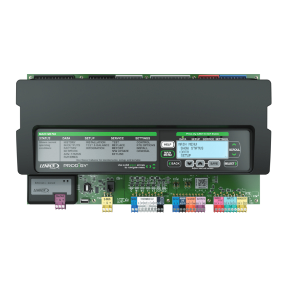
Page 8: M3 Unit Controller Layout And Connections
1.3. M3 Unit Controller Layout and Connections Connection for GP3 Control Connection for (A178) additional daughter-board EXPANSION EXPANSION PORT PORT Connection for C3 Control (A178) Only on 104661-xx) MODBUS connector To disconnect USB CONNECTION To disconnect TSTAT.COM from (for unit controller HMD.COM from COM cut jumper. -
Page 9: Main Controller Operation
2. Main Controller Operation 2.1. Control Type - Thermostat The M3 unit controller will operate the system from a wired thermostat, room sensor, zoning system using L Connection Zoning System based on the System Mode selected in SETTINGS > CONTROL > CONTROL TYPE = WIRED THERMOSTAT. -
Page 10: Heating Stages
Table 3. Thermostat Mode Operation (Three Cooling Stages Parameter 111) No Economizer With Economizer* Number of Compressors Y1 Demand Y2 Demand Adds Y3 Demand Adds Y1 Demand Y2 Demand Adds Y3 Demand Adds NO CHANGE NO CHANGE Free Cool NO CHANGE Free Cool (or two stage compressor) Free Cool... -
Page 11: System Mode - Room Sensor Backup Mode Set Points
Table 6. Default Thermostat Mode Operation (Gas Heat) (Energence LG 3 to 25 ton) No. of Heat Sections Gas Valve W1 Demand W2 Demand (1) 1 Stage Gas Valve 1 Gas Valve 1 (1) 2 Stage** Low Rate High Rate (2) 1 Stage High Rate - Both Valves High Rate - Both Valves... -
Page 12: Room Sensor Back-Up Mode Set Points
NOTE: Select the appropriate menu option to determine the room sensor back-up mode. The back-up mode is used in the event that the A2 room sensor fails or is disconnected. The following options are available: • NONE has no back-up mode of control should the A2 room sensor fail. •... -
Page 13: L Connection Network Back-Up Mode Requirements
2.2.4. L Connection Network Back-Up Mode Requirements Go to SETUP > NETWORK INTEGRATION wizard to configure a back up mode option. Table 10 references the wizard path to the backup mode setting. Table 10. Menu Interface (Level 1 - SETUP) LCONN ADDRESS = X •... -
Page 14: Start-Up Delay In Room Sensor Mode
2.2.5.2. Start-Up Delay in Room Sensor Mode In Room Sensor Mode, the M3 unit controller initiates a start up delay on any power-up or reset (two minute default). During the delay, no blower, heating, or cooling operation will occur. This delay may be adjusted using parameter 133 to stagger the start of each unit, reducing the initial power demand. - Page 15 Units With Economizer: Cooling stage-up timers: 15 minutes. Parameter 101 - Parameter 103 C1=Free Cooling 2°F Diff Cooling stage-down timers 15 minutes: Parameter 104 C2=Compressor 1 C3=Compressor 2 Parameter 147 C4=Compressor 3 + 4 1.5°F Diff C1=Cooling Stage 1 Parameter 146 C2=Cooling Stage 2 C3=Cooling Stage 3 1°F Diff...
-
Page 16: Unit Component Operation
On all other Energence models, Minimum OFF Time is enabled by default while Minimum Run Time is disabled by default. This method can be altered by modifying parameter 225 but can only be modified using the Lennox unit controller Software (UCS). -
Page 17: Energence Ultra-High Efficiency Units (3- To 6-Ton)
On certain compressors, these switches are in series with the high pressure switches, and will cause a 300 second delay (default) which is set using parameter 110. This will also set off an alarm. Adjustable delay range is 64 to 1800 seconds. Go to SETTINGS >... -
Page 18: Loss Of Power Detection (Single-Phase Units Only)
The default setting can be changed by using parameter 99. The valid number of occurrence range is 1 through 7. When a compressor is de-energized due to an open low pressure switch, alarm 22 (S87 switch) or 24 (S88 switch) is issued. Go to SETTINGS >... -
Page 19: Gas Valve Sensor Activation Feedback
3.2.4. Gas Valve Sensor Activation Feedback If M3 unit controller does not detect that gas valve is energized within two minutes after a heating demand, it will display and store error code 58 for gas heat section 1 and alarm 68 for gas heat section 2. If the gas valve is energized and de-energized three times (default) during a single heating demand, the M3 will display and store error code 59 for the gas heat section 1 and alarm 60 for gas heat section 2. -
Page 20: Air Flow Proving Switch (S52 - Optional)
Go to SETUP > INSTALL. Configuration ID 2, position 5 will need to be set to either 2 or 3 depending whether A42 is wired on DI-2 or DI-3. Using parameter 115 is only applicable if Safety switch A42 is enabled via Configuration ID 2. Go to SETTINGS >... -
Page 21: Unoccupied Or Night Setback Mode
• For gas units (Energence LG -3 to 6-ton), the blower off is delayed 180 seconds (default) from the time the heating call is terminated. This value is fixed and cannot be changed. • For cooling units, the blower off is delayed 60 seconds (default) from the time the cooling call is terminated. The blower delay is adjustable using parameter 80. -
Page 22: Gas Heat Operation-Gas Units
3.4. Gas Heat Operation—Gas Units The Prodigy system has gas heat output control for up to two gas heat sections with two-stage gas valves. NOTE: M3 unit controller controls the first heat circuit and C3 controls the second heat circuit. 3.4.1. -
Page 23: Sensors
4. Sensors The M3 unit controller is only compatible with L-Connection sensors provided with the unit or purchased separately as specified in the Product Specification. IMPORTANT All 0-10VDC sensors require two separate twisted pair cables with shield. One cable is used for the 24VAC power and one cable is used for the 0-10VDC output. -
Page 24: Supply Static Pressure Sensor - Optional
4.5. Supply Static Pressure Sensor - Optional The supply duct differential static pressure sensor (A30) is an analog sensor with a 0-10VDC output over a range of 0-5"w.c as shown in the following table. The sensor is powered with 24VAC. Table 15. -
Page 25: Outdoor Fan Operations
5. Outdoor Fan Operations 5.1. High Ambient Conditions 5.1.1. Energence Ultra-High Efficiency (7-1/2- to 20-ton) Under high ambient conditions (outdoor air temperature greater than 105°F), if one or both compressors are running, then all the fans corresponding to that circuit, run at speed set in parameter 96 - FAN HI AMBIENT SPD. When the outdoor air temperature drops below 100F, the fans will switch to normal ambient condition speed. -
Page 26: Compressor / Fan Configurations
5.4. Compressor / Fan Configurations See unit installation instruction or service manual for specific operational details. Table 16. Number of Compressors/Fans and Fan Layout Fan Layout Models Compr. Fans Size LCH, LGH 036S, 048S, A BOX 060S and 072H LCH, LGH 036H, 048H, A BOX (2 step) (variable) -
Page 27: Low Ambient Outdoor Fan Control And Cycling
5.5. Low Ambient Outdoor Fan Control and Cycling During low ambient conditions, various outdoor fans are cycled by liquid line pressure switches; S11, S84, S85 and S94. The M3 unit controller will also deenergize fans due to low outdoor temperature. See tables 17 through 21 for further details. -
Page 28: Energence B Box Standard, High And Ultra-High Efficiency Units (7.5-, 8.5-, 10-, 12- And 12.5-Ton)
5.5.2. Energence B Box Standard, High and Ultra-High Efficiency Units (7.5-, 8.5-, 10-, 12- and 12.5-Ton) Table 19. Low Ambient Fan Operations (B Box Standard, High and Ultra-High Efficiency Units) Associated Low Ambient Control Models Compressor OD Temp < Parameter 84 (55°F) 1, 2 LCH, LGH 092H, 102H, 120H, and 150S 1, 2... -
Page 29: Energence C Box High And Ultra-High Efficiency Units (13-, 15- And 20-Ton)
5.5.3. Energence C Box High and Ultra-High Efficiency Units (13-, 15- and 20-Ton) Table 20. Low Ambient Fan Operations (C Box Standard, High and Ultra-High Efficiency Units) Models Associated Low Ambient Control OD Temp Compressor < Parameter 84 (55°F) 1, 2, 3 On with S11 or S84 or S85 LCH, LGH 156H 2, 3... - Page 30 CONDENSER FANS C BOX 1 (B4) 3 (B21) Gas / Electric & Electric / Electric LC/LG 180H 15 Ton ANY−A55−K10 ANY−A178−K149 2 (B5) COMPRESSORS 4 (B22) 55ºF 55ºF A55−K1 A178−K14 A55−K2 ANY−A55−K68 ANY−A178−K150 CONDENSER FANS C BOX Gas / Electric & 4 (B22) 1 (B4) Electric / Electric...
-
Page 31: Energence C Box Standard And High Efficiency Units (17.5-, 20- And 25-Ton)
5.5.4. Energence C Box Standard and High Efficiency Units (17.5-, 20- and 25-Ton) Table 21. Low Ambient Fan Operations (C Box Standard and High Efficiency Units) Low Ambient Control OD Temp < Low Ambient Control Models Associated Compressor Parameters 84 (55°F) and > OD Temp <... - Page 32 CONDENSER FANS C BOX 1 (B4) 4 (B22) Gas / Electric & Electric / Electric 40ºF LC/LG 240H 20 Ton LC/LG 300S 25 Ton CP1 OR 2 −A55−K10 CP3 or 4 −A187 −K150 2 (B5) 5 (B23) 55ºF 55ºF CP 1 or 2 −A55−K68 CP3 or 4 −A178−K152 (3) B21 6 (B24)
-
Page 33: Dehumidification Operation
6. Dehumidification Operation Dehumidification mode is a combination of cooling to dehumidify and heating to maintain space temperature. ® Supermarket reheat uses gas heat and Humiditrol units route hot discharge gas to a reheat coil downstream of the ® ® evaporator. - Page 34 0 - 10VDC = 0-100% relative humidity J298A P298 AI-1 A91 HUMIDITY SENSOR DO-1 Two separate shielded cables required. One wire of the two pairs is not connected. DO-2 Figure 6. Relative Humidity Sensor Diagram Go to SETTINGS > RTU OPTION > EDIT PARAMETER = 106 (DEHUMID SETPOINT) and 107 (DEHUMID DEADBAND) (see paragraph 6.3.
-
Page 35: Third Party Digital Input To Control Dehumidification
6.3. Third Party Digital Input to Control Dehumidification 1. Go to SETUP > INSTALL. Set Configuration ID1, position 1 to H for Humiditrol option. Follow the wizard until sensor type option is prompted and select REHEAT DI4. 2. An alternate method is to Go to SETTINGS >... -
Page 36: Compressor And Humiditrol Operation
6.6. Compressor and Humiditrol Operation Table 23. 1-Compressor Humiditrol Default Operation (Using 2-Stage Wired Thermostat or Room Sensor) Unit Operation Demands Summary Idle. CP1 Reheat (Reheat Stage 1) CP1 Reheat (Reheat Stage 1) CP1 Cool Free Cool CP1 Cool CP1 Cool CP1 Cool Free Cool, CP1 Cool CP1 Cool... - Page 37 Table 25. 2-Compressor Humiditrol Default Operation (using 3Stage Thermostat DDC with Zone Sensor) Demands Condition Unit Operation Free Air Compressor Blower Speeds Reheat Damper Humidity Valve 1 Thermostat Cool Cool (Economizer) Sensor Vent Heat Unoccupied Closed Occupied Minimum Modulate up to Suitable Maximum Modulate up to...
- Page 38 Table 27. 3-Compressor Humiditrol Default Operation (using 3Stage Thermostat) Demands Condition Unit Operation Blower Speeds Compressor Free Air Damper (Economizer) Trigger Cool Cool Cool Cool Vent Heat Unoccupied OFF OFF OFF Closed Occupied OFF OFF OFF Minimum Modulate up to Suitable OFF OFF OFF Maximum...
- Page 39 Table 28. 3-Compressor Humiditrol Default Operation (using 4Stage Thermostat with Zone Sensor) Demands Condition Unit Operation Blower Speeds Compressor Free Air Damper (Economizer) Trigger Cool Cool Cool Cool Vent Heat Unoccupied OFF OFF OFF Closed Occupied OFF OFF OFF Minimum Modulate up to Suitable OFF OFF OFF...
- Page 40 Table 29. 4-Compressor Humiditrol Default Operation (using 2stage Thermostat) Demands Condition Unit Operation Blower Speeds Compressor Free Air Damper (Economizer) Trigger Cool Cool Cool Cool Vent Heat Unoccupied OFF OFF OFF OFF Closed Occupied OFF OFF OFF OFF Minimum Modulate up to Damper position Suitable OFF OFF OFF OFF...
- Page 41 Table 30. 4-Compressor Humiditrol Default Operation (using 3stage Thermostat) Demands Unit Operation Free Air Damper Blower Speeds (Economizer) Compressor Trigger Cool Cool Cool Cool Vent Heat Unoccupied OFF OFF OFF OFF Closed Occupied OFF OFF OFF OFF Minimum Modulate up to Suitable OFF OFF OFF OFF Maximum...
- Page 42 Table 31. 4-Compressor Humiditrol Default Operation (using 4stage Thermostat, DDC with Room Sensor) Demands Unit Operation Free Air Damper Blower Speeds (Economizer) Compressor Trigger Cool Cool Cool Cool Vent Heat UNOCP OFF OFF OFF OFF Closed OFF OFF OFF OFF Minimum Modulate up to Suitable...
-
Page 43: Increased Dehumidification Operation - Energence Ultra-High Efficiency (3- To 6-Ton)
7. Increased Dehumidification Operation - Energence Ultra-High Efficiency (3- to 6-ton) Energence Ultra-High Efficiency 3 to 6-ton units do not support humidity control as described in Section 6, instead they use Increased dehumidification for these models. 7.1. Increased Dehumidification in Wired Thermostat Mode Increased Dehumidification mode can be activated by the M3 unit controller only when a cooling demand is present. -
Page 44: How To Enable Or Disable Increased Dehumidification Mode
7.3. How to Enable or Disable Increased Dehumidification Mode Go the MAIN MENU > SETUP > INSTALL. Follow the prompts until you reach MODEL NUMBER. Enter the Ultra-High Efficiency model number here. Touch SAVE to proceed. Continue through the various configuration problems until you reach DEHUM SENSOR TYPE. -
Page 45: Economizer
8. Economizer 8.1. General The economizer, when configured, controls: • Damper position, which determines how much outdoor air is used to meet free cooling or indoor air quality requirements, and • Optional power exhaust fans. On a cooling demand, outdoor air is used for free cooling instead of first-stage compressor(s) when outdoor air is suitable. 8.2. -
Page 46: Enthalpy Set Point
8.6. Enthalpy Set Point This setting pertains to the single enthalpy free cooling mode only. The M3 unit controller will enable free cooling when outdoor air enthalpy (A7) is less than the enthalpy set point (parameter 162 - ECON FREECL ENTH SP). Figure 8 shows the approximate enthalpy sensor output at various temperatures and percentage of relative humidity. -
Page 47: Economizer Checkout
8.11. Economizer Checkout The following checkout procedures are completed with unit energized. Step 1 will determine whether the economizer is allowing full damper travel. Use step 2 when the damper does not respond to step 1. Steps 3, 4, 5, and 6 checkout the operating modes; checkout only the mode that applies to the unit being worked on. CAUTION Power exhaust fans will be functional. - Page 48 Refer to the “Displaying Sensor Inputs" section to read return air (RT16) and outdoor air (RT17) temperatures. If outdoor air is not cooler than return air, simulate a colder outdoor air temperature with a resistor. Select a resistor value that corresponds to a temperature (see table 32): Locate RT17 sensor in unit.
-
Page 49: Demand Control Ventilation (Dcv)
9. Demand Control Ventilation (DCV) 9.1. General A field-provided and installed indoor air quality (IAQ) sensor can be used with the modulating economizer or motorized outdoor air damper (OADM) to control carbon dioxide levels in the conditioned space. The carbon dioxide level in a space is an indicator of the number of people occupying a room. -
Page 50: Parameter Adjustments
Low Temp. Operation High Temp. Operation 40°F Parameter 75°F Parameter 121 30°F 85°F 20°F 95°F Min. Position 10°F Parameter 122 105°F Parameter 120 1000 Parameter 118 Parameter 119 (ppm) Figure 10. Default Demand Control Ventilation (DCV) Operation 9.4. Parameter Adjustments Default indoor air quality economizer operation is based on common or average applications. -
Page 51: Determining Indoor Air Quality Inputs
Parameter 117 Max. Open Close Open Min. Position Parameter 119 Parameter 118 (full) (start) carbon dioxide (ppm) Figure 11. Set point Control Indoor Air Quality Option 9.4.2. Determining Indoor Air Quality Inputs Go to DATA> IN/OUTPUTS > SENSORS menu selection from the M3 unit controller menu display. -
Page 52: Outdoor Air Control (Oac)
10. Outdoor Air Control (OAC) ® This feature is available on all models except Energence 3 to 6-ton units with Advanced Airflow Control enabled. Outdoor Air Control cannot be enabled on systems configured as indicated. Outdoor Air Control is an alternative to Demand Control Ventilation for modulating the outdoor air damper in order to hold a constant outdoor airflow. -
Page 53: Building Pressure Control (Bpc)
11. Building Pressure Control (BPC) The M3 unit controller supports building pressure control of ventilation. This feature will modulate the outdoor air damper in order to hold a constant building pressure. This mode requires an A34 building pressure sensor to be installed on M3 unit controller IAQ input (instead of CO2 sensor). -
Page 54: Power Exhaust Operation
12. Power Exhaust Operation The M3 unit controller is capable of controlling up to two stages of power exhaust. The M3 unit controller configuration has to match the power exhaust equipment installed in the roof top unit: To enable the Power Exhaust feature in the software, set Configuration ID 1 position 3 to either S or D (whichever is applicable). -
Page 55: Supply Air Delivery
13. Supply Air Delivery 13.1. Blower Delays The following is summary of blower delay options, For more details refer to sections 3.3.9 and 3.3.10. 13.1.1. Gas / Electric Units The blower default delay is 40 seconds (parameter 66 HT GAS BLR ON DELAY) after the gas valve is energized and a default of 120 seconds (parameter 67 ... -
Page 56: Supply Constant Air Volume (Cav) With Zone Bypass Damper Control
13.5. Supply Constant Air Volume (CAV) with Zone Bypass Damper Control Configuration ID 2 position 7 must be set to Y to enable Prodigy 2.0 Zone bypass operation with Constant Air Volume. This configuration is used for L Connection or third-party zoning systems that utilize a blower bypass damper for controlling duct static pressure. -
Page 57: Analog Output Control
13.5.2. Analog Output Control The analog output on the M3 unit controller (P2594) is set to closed loop PID or staged control when configured for Constant Air Volume bypass damper (Configuration ID 2, position 7 must be set to Y). The closed loop PID method used by the M3 unit controller has three constants manual resets;... -
Page 58: Tuning
13.5.2.5. Tuning In the event that the PID loop requires tuning, the following two methods are recommended depending on the severity of the problem: 1. In most cases the parameters will only need a small adjustment. In that case use the following table as a basic guide. Table 39. -
Page 59: Discharge Air Control
14. Discharge Air Control 14.1. Cooling The discharge air control cooling option automatically cycles up to 4-stages of cooling to maintain a discharge air control cooling set point. • When an economizer is installed, adjust free cooling set point parameter 159 approximately 2 degrees lower than Discharge Air Control Cooling set point. -
Page 60: Discharge Air Control Cooling (Dacc) Outdoor Air Temperature Reset
The DACC OAT Reset and free cooling set point can be automatically reset when outdoor air temperature becomes cooler. • For DACC OAT Reset, use the Lennox UC software to access parameter 287 and enable DACC Outdoor Air Temperature Reset. •... -
Page 61: Discharge Air Control Cooling (Dacc) Return Air Temperature Reset
NOTE: Parameter 287 cannot be modify directly from the M3 unit controller interface. • For DACC RAT Reset, use the Lennox UC software to access parameter 287 and enable DACC RAT Reset. • For DACC RAT Reset, the discharge air cooling set point starts to increase when the return air temperature drops to the parameter 205 (DACC RAT RS ADJ SP) which has a default of 70.0°F. -
Page 62: Discharge Air Control Cooling (Dacc) Total Reset Limit
To use example values, set the following parameters: • Parameter 205 – Set to 70.0°F • Parameter 206 – Set to 10.0°F • Parameter 204 – Set to 10.0°F (this setting enables Discharge Air Control Cooling return air reset). 14.1.3. Discharge Air Control Cooling (DACC) Total Reset Limit Parameter 207 with a default setting of 10.0°F defines the total Discharge Air Control Cooling set point reset limit. -
Page 63: Discharge Air Control Heating (Dach) Outdoor Air Temperature Reset
Discharge Air Control Heating (DACH) Outdoor Air Temperature Reset NOTE: Parameter 287 cannot be modify directly from the M3 unit controller interface. • Using the Lennox UC software, access parameter 287 and enable DACH Outdoor Air Reset. If using the Lennox UC software. •... -
Page 64: Discharge Air Control Heating (Dach) Total Reset Limit
Parameter 213 (DACH RAT RS PRP BND) ° Example 10.0 ° Parameter 211 (DACH RAT RS ADJ BND) Example ° 10.0 DACH Set point ° 100.0 ° ° Reset Set point Approx.105.0 F (at 75.0 ° ° 70.0 80.0 Return Air Temp. RAT) Parameter 212 (DACH RAT RS ADJ SP) Figure 18. -
Page 65: Third-Party Zoning
15. Third-Party Zoning The M3 unit controller is only compatible with bypass damper actuators specified in the Product Specification bulletin. Figure 19 is a Constant Air Volume with bypass damper unit wiring summary. In addition to providing bypass damper control (Constant Air Volume units), the M3 unit controller provides discharge air control for cooling and/or heating. -
Page 66: Discharge Air Control Heating Outdoor Air Reset
15.4.1. Discharge Air Control Heating Outdoor Air Reset The outside air reset saves energy by gradually decreasing the discharge air set point as the outside air temperature increases. Refer to section 14.2.1. for further details. 15.4.2. Discharge Air Control Heating Return Air Reset The return air reset reduces the possibility of overheating by gradually decreasing the discharge air set point as the return air temperature increases. -
Page 67: Bacnet
MSTP network. The BACnet module conforms to the BACnet application specific controller (B-ASC) device profile. A Lennox non-communicating room sensor, a BACnet network room sensor, or a BACnet thermostat may be used to send the room temperature or thermostat demands to the M3. -
Page 68: Analog Output Objects
ONLY at the ends of the chain. Cable type - twisted pair with shield, 22 awg minimum, (not terminated) (terminated) (terminated per mfg Belden #88761 or #8761 (Lennox 27M19, 94L63, 68M35). instructions) Figure 21. Terminating ends of daisy-chained networks 16.4. Analog Output Objects Optional Properties Supported:... -
Page 69: Analog Value Objects
16.5. Analog Value Objects Optional Properties Supported: None Optional Writable Properties: Present_Value Table 42. Analog Value Objects List Object Min. Max. Valid Values within Object Name Units Note Value Value Range 9600, 19200, 38400, Baud Rate Setting None 9600 76800 38400 default 76800 Heating Occupied Set... -
Page 70: Analog Input Objects
16.6. Analog Input Objects Optional Properties Supported: None Optional Writable Properties: Out_Of_Service (AI239 - AI252, AI274 - AI285 only) Table 43. Analog Input Objects List Object ID Object Name Units Data Range Mac Address None 0 − 127 IMC Address None 1−31 200*... - Page 71 Table 43. Analog Input Objects List Object ID Object Name Units Data Range Most Recent Error 10 None 1 − 255 Space Carbon Dioxide Sensor (Effective) Parts−per−million 0 − 2000 Space Carbon Dioxide Sensor (Local) Parts−per−million 0 − 2000 Space Humidity (Effective) Percent 0 −...
- Page 72 Table 44. Lennox Proprietary Objects - Compressor (Object ID: 136) Property Property ID Data type and range Access Description Numeric code that identifies the object (unique with Object_Identifier Integer (0-4194302) Read Only in Lennox BACnet Device). character string of 1 character...
- Page 73 Table 46. Lennox Proprietary Objects - Heating (Object ID: 130) Property Property ID Data type and range Access Description Numeric code that identifies the object (unique with Object_Identifier Integer (0-4194302) Read Only in Lennox BACnet Device). character string of 1 character...
-
Page 74: M3 Unit Controller Bacnet Module Installation
Integer (0 - 255) Read Only encountered. A value of 0 means no error while any non-zero value represent an error. Table 48. Lennox Proprietary Objects - Discharge Air (Object ID: 133) Property Property ID Data type and range Access Description Numeric code that identifies the object (unique with... -
Page 75: Comfort Sensors
NOTE: Additional settings will be required to complete the configuration after entering the baud rate. 16.8. Comfort Sensors BacNet Configuration To enable the M3 Unit Controller to use Comfort Sensors, use the following procedure: 1. Confirm that the Configuration ID 1, position 5 has been set to B as mentioned in the previous section. 2. -
Page 76: Lontalk
17. LonTalk ® For complete information on how to perform the physical installation of LonTalk , please refer to 506693-01, LonTalk Module Kit (54M27). 17.1. Setup To enable the LonTalk module, go to: 1. SETUP > INSTALL and run the setup wizard. When Configuration ID 1 appears on the screen, configure position 5 as L. -
Page 77: L Connection Network
The Building Controller (BC) is used to control building functions such as lights and signs. Use L connection specific network cable and daisy chain as shown in figure 23. SYS BUS TERMINAL BLOCK ON LENNOX SYS BUS TERMINAL BLOCK... -
Page 78: Load Shedding Options
19. Load Shedding Options The M3 unit controller may be setup to de-energize part or all of the mechanical cooling provided by a rooftop unit. Configuration ID 2, position 8 defines where the digital input for load shedding is configured. Go to SETUP >... -
Page 79: Service Relay
20. Service Relay 20.1. Service Relay Operation The M3 unit controller Service Relay output (A55_P298-8) default operation indicates that service is required. If the default operation is not required, the Service Relay output may be used as a control output. Use parameter 186 to choose the input which will trigger the Service Relay output. - Page 80 1. Determine: Dehumidifier On Parameter 186 - Input Source X to option “7" (relative humidity) Algorithm Y to option “0" (hysteresis loop) Inversion Z option “0" (output not inverted) 2. Apply step 1 to parameter 186 formula: Parameter 186 = X + (32 Y) + (16 = 7 + (32 0) + (16...
-
Page 81: Advanced Airflow System (Smart Airflow™)
™ 21. Advanced Airflow System (Smart Airflow Applicable to Energence High Efficiency 3 to 5-ton units and Ultra-High Efficiency 3 to 6-ton units. The optional factory installed Advanced Airflow System employs a pressure sensor equipped economizer and an ECM blower motor. This feature enables the Prodigy M3 unit controller to accurately measure and control the Supply Airflow and Outdoor Airflow. -
Page 82: Outdoor Airflow (Oa) Measurement And Control
21.3. Outdoor Airflow (OA) Measurement and Control Target OA is calculated for all the modes (DCV, Free Cooling, Minimum Run) individually when there is a change in the supply airflow target or minimum and maximum OA targets (parameters 237, 241 and 242). DCV and minimum run modes will be active only if occupied. -
Page 83: Sequence Of Operation
Three stage cool operation is possible with special setting described in section 2.1.1. Constant volume units in either single-zone or bypass zoning applications can use this control mode. To operate correctly, a Lennox or third-party thermostat or unit control must provide the following wiring connections to the M3 unit controller: 1. - Page 84 Although not as common, constant volume units in either single-zone or bypass zoning applications may also use this control mode. To operate correctly, a Lennox or third-party thermostat or unit control must provide the following wiring connections to the M3 unit controller: 1.
-
Page 85: Operations Common To All Rooftop Units
The user can change these settings ® either locally or remotely through Lennox L Connection Network unit controller Software. The user will not have the ability to adjust the settings through third-party software or control devices. -
Page 86: Discharge Air Cooling Reset Operation
IMPORTANT For fresh air tempering modes to operate properly, the RT6 discharge sensor must be relocated to the supply air duct. 22.1.3.4. Discharge Air Cooling Reset Operation Discharge air cooling reset operation saves energy by gradually increasing the discharge air set point as outside air temperature decreases. -
Page 87: Cav Units In Single-Zone Applications With A Lennox Room Sensor
Unit Controller Operation (4-Heat / 4-Cool) When using a Lennox room sensor with the M3 unit controller operating in room sensor mode, a packaged rooftop unit can provide up to four stages each of mechanical heating and cooling operation. The room sensor provides space temperature information to the M3 unit controller. -
Page 88: Humiditrol Dehumidification Operation - Dehumidification Demand
22.2.7. Humiditrol Dehumidification Operation - Dehumidification Demand Upon a dehumidification only demand, the M3 unit controller activates various compressors depending on model for reheating. At the same time, the M3 unit controller will use the solenoid valve(s) to divert hot gas from the compressor(s) to the reheat coil. -
Page 89: Cooling Demand With Economizer
If the unit is unable to satisfy the call for cooling within a specified time period and receives a stage two cooling demand from the thermostat or third-party temperature control, the M3 unit controller activates additional compressors in order to provide 100% cooling capacity. -
Page 90: Humiditrol Dehumidification Operation - Cooling And Dehumidification Demand
The discharge supply air temperature set point resides in the M3 unit controller, has a factory default setting, and can be adjusted at start-up. The user can adjust the set point either locally or remotely with Lennox L Connection Network unit controller software or at the M3 unit controller. -
Page 91: Heating Demand (General Operation)
M3 unit controller, has a factory default setting, and may be adjusted at start up. The user can adjust the set point either locally or remotely with Lennox L Connection Network unit controller software or at the M3 unit controller. -
Page 92: Bypass Zoning Applications (4-Heat / 4-Cool)
22.3.4. Bypass Zoning Applications (4-Heat / 4-Cool) 22.3.4.1. Unit Controller Operation When using a third-party controller and the M3 unit controller is operating in thermostat mode and configured for discharge air temperature control, a packaged rooftop unit can provide up to four stages of mechanical heating and cooling operation. -
Page 93: M3 Unit Controller Inputs And Outputs
23. M3 Unit Controller Inputs and Outputs Figure 31. Wiring Diagram... -
Page 94: M3 User Interface Menu Tree And Display Status Screen
24. M3 User Interface Menu Tree and Display Status Screen 24.1. Menu Tree (Level 1) SELECT BACK ALARMS, ZAT, DAT, OCC OR UNOCC, SCROLL DEMAND STATUS ALARMS SHOW STATUS PRESENT? ZAT, DAT, OCC DATA OR UNOCC, DEMAND SETUP STATUS SERVICE SETTINGS HISTORY INSTALL... -
Page 95: Menu Interface Details
24.2. Menu Interface Details The following tables indicate the major levels of the menu interface. Many of these options have more levels which are described in the following sections that detail DATA, SETUP, SERVICE, and SETTINGS. Use the SELECT button to progress to the next menu level (i.e. level 1 to level 2). Use the SCROLL arrows ▲▼... - Page 96 Table 56. Menu Interface (Level 1 - DATA) Level 2 Level 3 Level 4 Level 5 Level 6 COMPRESSOR 1: ON/OFF COMPRESSOR 1: ON/OFF COMPRESSOR 3: ON/OFF COMPRESSOR 4: ON/OFF BLOWER: ON/OFF EXHAUST: ON/OFF FAN 1: ON/OFF FAN 2: ON/OFF FAN 3: ON/OFF FAN 4: ON/OFF FAN 5: ON/OFF...
- Page 97 Table 56. Menu Interface (Level 1 - DATA) Level 2 Level 3 Level 4 Level 5 Level 6 CURRENT ALARMS ACTIVE ALARMS XXX OCC HEAT UNOCC HEAT SETPOINTS OCC COOL UNOCC COOL APP MODE BLOWER SPEED X RPM. BLOWER BLOWER STATUS ADVANCED SUPPLY TARGET X CFM...
-
Page 98: Setup
24.2.3. Setup Table 57. Menu Interface (Level 1 - SETUP) Level 2 Level 3 Level 4 Level 5 Level 6 Level 7 LANGUAGE = = ENGLISH, ESPANOL, OR FRANCAIS DATE/TIME = = DAY, MONTH, YEAR, HOURS, MINUTES, SECONDS DISPLAY UNITS F/C = FAHRENHEIT OR CELSIUS MODEL NUMBER = LOCATED ON UNIT NAMEPLATE. - Page 99 Table 57. Menu Interface (Level 1 - SETUP) Level 2 Level 3 Level 4 Level 5 Level 6 Level 7 LCONN ADDRESS = X • NETWORK SENSOR CO2 = YES OR NO • NETWORK SENSOR RELATIVE HUMIDITY = YES OR NO •...
- Page 100 Table 57. Menu Interface (Level 1 - SETUP) Level 2 Level 3 Level 4 Level 5 Level 6 Level 7 BLOWER HEATING HIGH = XXXX CFM BLOWER COOLING HIGH = XXXX CFM BLOWER COOLING LOW = XXXX CFM BLOWER VENTILATION = XXXX CFM ON (TARGET XXXX CFM) ADJUST BLOWER RPM = XXXX RPM BLOWER STARTING BLOWER >...
-
Page 101: Service
Table 57. Menu Interface (Level 1 - SETUP) Level 2 Level 3 Level 4 Level 5 Level 6 Level 7 OUTDOOR AIR CONTROL (ONLY VISIBLE IF CONFIGURATION ID 1, POSITION 8 IS SET VELOCITY SETPOINT = XXX FT/MIN CORRECTLY) POWER EXHAUST ON BY ECON TRAVEL = XX.X % FRESH AIR HEATING ENABLE FAH = NO OR FRESH AIR HEATING FAH SETPOINT = XX F... - Page 102 Table 58. Menu Interface (Level 1 - SERVICE) NOTE: AVAILABLE MENU OPTIONS ARE DEPENDENT ON HARDWARE CONFIGURATION. TEST MENU SECTION: EACH MAJOR COMPONENT OF THE M3 UNIT CONTROLLER WILL INCLUDE A TEST MODE TO VERIFY CRITICAL COMPONENT AND SYSTEM PERFORMANCE. ALL BLOWER TESTING WILL REMAIN ACTIVE FOR TWO HOURS UNLESS TERMINATED BY THE USER.
-
Page 103: Settings
24.2.5. Settings Table 59. Menu Interface (Level 1 - SETTINGS) NOTE: AVAILABLE MENU OPTIONS ARE DEPENDENT ON HARDWARE CONFIGURATION. USE THE ADJUST AND SET VALUES ARROWS TO SCROLL UP OR DOWN FOR SELECTION OPTIONS. Level 2 Level 3 Level 4 Level 5 Level 6 Level 7... - Page 104 Table 59. Menu Interface (Level 1 - SETTINGS) NOTE: AVAILABLE MENU OPTIONS ARE DEPENDENT ON HARDWARE CONFIGURATION. USE THE ADJUST AND SET VALUES ARROWS TO SCROLL UP OR DOWN FOR SELECTION OPTIONS. Level 2 Level 3 Level 4 Level 5 Level 6 Level 7 CONTROL MODE = MONITOR...
- Page 105 Table 59. Menu Interface (Level 1 - SETTINGS) NOTE: AVAILABLE MENU OPTIONS ARE DEPENDENT ON HARDWARE CONFIGURATION. USE THE ADJUST AND SET VALUES ARROWS TO SCROLL UP OR DOWN FOR SELECTION OPTIONS. Level 2 Level 3 Level 4 Level 5 Level 6 Level 7 ECONOMIZER ENTHALPY OFFSET = X MA...
- Page 106 Table 59. Menu Interface (Level 1 - SETTINGS) NOTE: AVAILABLE MENU OPTIONS ARE DEPENDENT ON HARDWARE CONFIGURATION. USE THE ADJUST AND SET VALUES ARROWS TO SCROLL UP OR DOWN FOR SELECTION OPTIONS. Level 2 Level 3 Level 4 Level 5 Level 6 Level 7 DEHUMIDIFIER DEHUMID SETPOINT = X.XX %...
-
Page 107: System Status Screen
24.3. System Status Screen System Status Screen The display shows operating mode if in normal operation. Alarms will interrupt the display. Alarm messages will appear on the display and remain there until dismissed. Dismissing an alarm is just clearing the alarm from using the entire screen to display the condition(s). -
Page 108: Normal Mode And Status Messages
24.3.4. Normal Mode and Status Messages The format of the message is mode and setpoint (see table 61). Table 61. Possible Demand and Status Messages COMP LOAD SHEDDING Unit is running at lower power capacity COOLING Cool demand present; unit is in mechanical cooling. DEHUMIDIFICATION Unit is dehumidifying FREE COOLING... -
Page 109: Led Operations
24.4. LED Operations LED Indicators: Some indicators on the circuit board are visible with the cover in place; others are not. The indicators and their meanings are described in table 62. Table 62. LED Operation Indicators Status Indication Meaning Green Slow Flash Normal Operation Green... -
Page 110: Model Number And Configuration Id 1 And 2
25. Model Number and Configuration ID 1 and 2 This section addresses the requirement that specific configuration information must be completed using the SETUP / INSTALL feature if a new unit controller was being installed. Other requirements are the addition of accessories that were not factory-installed. -
Page 111: Configuration Id 1
N = Not Installed A34 Pressure Sensor with B = BACnet Enable Switch = D L = LonTalk (Lennox) S27 and S39 Pressure Switch = E NOTE: The M3 unit controller will display applicable alarm(s) if any positions is left unconfigured (U). -
Page 112: Configuration Id 2
Installed on DI-3 = 3 Detection* N = Not Installed 1 = Enabled Internal (Lennox) * When Phase / Voltage detection monitoring is enabled on three-phase system and configured incorrectly will cause the system to go to demand hold and restart after 2 = External (A42) Phase Detection 3 minutes. -
Page 113: M3 Unit Controller Parameters
26. M3 Unit Controller Parameters Many M3 unit controller operations may be modified within a set range. Default settings are based on common or average applications; change parameter settings only when custom applications, preferences or local building codes exist. Default, minimum, and maximum range settings are found in table 63. NOTICE: Units with Novar 2051 module! Failure to perform the following steps may result in unsatisfactory unit operation. - Page 114 Table 63. M3 Control Parameters Control Parameter Control Value Parameter Short Description Screen Name Min. Default Max. Units Description = ENGLISH, Select desired language for ESPA (SPAN LANGUAGE LANGUAGE Option user interface. Options are Eng ISH) or FRAN lish, French and Spanish. (FRENCH) Power and Damper Parameters Applicable to Energence Stan...
- Page 115 Table 63. M3 Control Parameters Control Parameter Control Value Parameter Short Description Screen Name Min. Default Max. Units Units Description Description Multi-Stage Air Volume Smoke Detection Mode (Alarm) NOTE: In order for the SMOKE Check unit CFM change to take affect, go Multi-Stage Air Volume parameter label the SETUP >...
- Page 116 Table 63. M3 Control Parameters Control Parameter Control Value Parameter Short Description Screen Name Min. Default Max. Units Units Description Description • Constant air volume with by pass damper minimum out put for cooling, ventilation Constant Air Volume with and during smoke alarms. Bypass Damper This sets the minimum air Minimum Output...
- Page 117 Table 63. M3 Control Parameters Control Parameter Control Value Parameter Short Description Screen Name Min. Default Max. Units Units Description Description Electric Heating Parameters Warm-up time delay. The time Electric Heat Warm-up that the economizer is forced HT ELEC WARMUP Time Delay for 3584 8160...
- Page 118 Table 63. M3 Control Parameters Control Parameter Control Value Parameter Short Description Screen Name Min. Default Max. Units Units Description Description • Stage-up timer. The maxim um time that lower stage runs before calling next heat HT GAS STG UP TMR Gas Stage Up Timer 3600 Seconds...
- Page 119 Table 63. M3 Control Parameters Control Parameter Control Value Parameter Short Description Screen Name Min. Default Max. Units Units Description Description • Low ambient lockout for compressor 2. Check unit para • A value of (-31F) will disable Low Ambient meter label as COMP2 LO TMP low ambient lockout function.
- Page 120 Table 63. M3 Control Parameters Control Parameter Control Value Parameter Short Description Screen Name Min. Default Max. Units Units Description Description • Stage 4 stage up timer. The maximum time that cooling stage 3 runs before calling Maximum Stage 3 cooling stage 4.
- Page 121 Table 63. M3 Control Parameters Control Parameter Control Value Parameter Short Description Screen Name Min. Default Max. Units Units Description Description When outdoor air is suitable for Free Cooling Low free cooling and an economizer FREE LO AMB LCKT Ambient Lockout Set 45.0 55.0 80.0...
- Page 122 Table 63. M3 Control Parameters Control Parameter Control Value Parameter Short Description Screen Name Min. Default Max. Units Units Description Description Block 5 Miscellaneous Parameters Heating staging options: No heating operation. HEAT STAGING Heating Staging Option Option Discharge air control with OPTION up to four stages.
- Page 123 Table 63. M3 Control Parameters Control Parameter Control Value Parameter Short Description Screen Name Min. Default Max. Units Units Description Description OAC PID P CON Outdoor Air Control PID Outdoor Air Control PID P Con Counts STANT P Constant stant Outdoor Air Control PID I Outdoor Air Control PID I Con...
- Page 124 Table 63. M3 Control Parameters Control Parameter Control Value Parameter Short Description Screen Name Min. Default Max. Units Units Description Description • Backup unoccupied heating set point. Used if the com munications link is lost for 5 minutes between the M3 and NCP.
- Page 125 Table 63. M3 Control Parameters Control Parameter Control Value Parameter Short Description Screen Name Min. Default Max. Units Units Description Description • Cooling stage 2 differential. Used only with room sensor applications. Cooling Stage 2 COOL STAGE2 DIFFER 0.00 1.00 3.00 °F •...
- Page 126 Table 63. M3 Control Parameters Control Parameter Control Value Parameter Short Description Screen Name Min. Default Max. Units Units Description Description Blower control option for room sensor applications during oc cupied periods. • Auto Cycle: Blower cycles with demand • On-Continuous 1: blower is on with either the occupancy sensor or occupancy sched...
- Page 127 Table 63. M3 Control Parameters Control Parameter Control Value Parameter Short Description Screen Name Min. Default Max. Units Units Description Description These are the operating profile options for the economizer damper during free cooling when any compressor is on and can be selected as follows: Option 0: Damper continues to modulate while compressors...
- Page 128 Table 63. M3 Control Parameters Control Parameter Control Value Parameter Short Description Screen Name Min. Default Max. Units Units Description Description Fresh Air Heating Fresh air damper position dur FAH REHEAT DAMPER Control Reheat Damper 40.0 100.0 ing Fresh Air Heating reheat op Position eration.
- Page 129 Table 63. M3 Control Parameters Control Parameter Control Value Parameter Short Description Screen Name Min. Default Max. Units Units Description Description A55 Service Output Control Mode = X + 32*Y + 16*Z Input source = X: None Compressor 1 duty cycle.
- Page 130 Table 63. M3 Control Parameters Control Parameter Control Value Parameter Short Description Screen Name Min. Default Max. Units Units Description Description Service Output Set Point Service Output Set Point Tem SRV OUTPT SP TEMP -31.0 51.0 132.0 °F Temperature perature Service Output A55 service relay output dead- SRV OUTPT DB C02...
- Page 131 Table 63. M3 Control Parameters Control Parameter Control Value Parameter Short Description Screen Name Min. Default Max. Units Units Description Description • Discharge Air Control Cool ing return air reset propor Discharge Air Control DACC RAT RS PRP tional band. Cooling Return Air Reset 10.0 30.0...
- Page 132 Table 63. M3 Control Parameters Control Parameter Control Value Parameter Short Description Screen Name Min. Default Max. Units Units Description Description Applicable to Energence Stan dard Efficiency 3- to 6-ton units only. Advanced Airflow Hi CL HI SPD CALIB -1200 1200 Count If the absolute value of this...
- Page 133 Enable High Outdoor Temp override of DCV/OAC operation (ALGO_HI_OAT_DCV_OAC_OVERRIDE) 0x00000800 Enable Free Cooling Blower Stage Up Here is an example of the selection options for Algorithms Enable via the Lennox UC Software. Heartbeat configuration propriet ies define how often a network...
- Page 134 Table 63. M3 Control Parameters Control Parameter Control Value Parameter Short Description Screen Name Min. Default Max. Units Units Description Description Building Pressure BPC PID I CONST Count BPC PID Integral Constant Control PID I Constant 1 - Occupied - PID set point A Unoccupied - PID set point B 2 - Occupied - PID set point A Unoccupied -Staged output B...
- Page 135 Table 63. M3 Control Parameters Control Parameter Control Value Parameter Short Description Screen Name Min. Default Max. Units Units Description Description Source/feedback for the PID loop. General Purpose A02 SOURCE GP A02 SOURCE 1 = Analog input 1 on GP3 A02 Source SELECTION 2 = Analog input 2 on GP3 A02...
- Page 136 Table 63. M3 Control Parameters Control Parameter Control Value Parameter Short Description Screen Name Min. Default Max. Units Units Description Description Source/feedback for the PID loop. General Purpose A03 GP A03 SOURCE SOURCE 1 = Analog input 1 on GP3 A03 Source 2 = Analog input 2 on GP3 A03 3 = Analog input 3 on GP3 A03...
- Page 137 Table 63. M3 Control Parameters Control Parameter Control Value Parameter Short Description Screen Name Min. Default Max. Units Units Description Description General Purpose D01 GP D01 TIME DELAY 8160 For delay on or delay off. Time Delay GP3 Digital Out Control Mode = X + 32*Y + 16*Z Input Sources X: 0- None.
- Page 138 Parameter 358 Windowed Hysteresis Loop Algorithm Y for Input Sources 7-15: 0- Hysteresis loop • On when input > = set point • Off when input < set point - dead-band percentage (P 363) 1- Window • On when input is in range > = setpoint setpoint setpoint and <...
- Page 139 Parameter 365 Algorithm Y for Input Sources 7-15: Hysteresis Loop Windowed 0- Hysteresis loop • On when input > = set point • Off when input < set point - dead-band percentage (P 370) 1- Window • On when input is in range > = setpoint and <...
-
Page 140: M2 Ecto To M3 Parameter Cross-References
27. M2 ECTO to M3 Parameter Cross-References Table 64. M2 ECTO to M3 Parameter Cross-Reference Accessible via ECTO M3 Parameter M3 Parameter Name Settings Menu 0.01 Variable Air Volume Control Mode 0.02 Blower Smoke Output 0.03 NONE 0.04 Blower Heat Output 0.05 Blower Cool Output 0.06... - Page 141 Table 64. M2 ECTO to M3 Parameter Cross-Reference Accessible via ECTO M3 Parameter M3 Parameter Name Settings Menu 1.13 Maximum Low Pressure Occurrences 1.14 NONE 1.15 NONE 1.16 NONE 1.17 NONE 1.18 NONE 1.19 NONE 1.20 NONE 1.21 NONE 1.22 NONE 1.23 NONE...
- Page 142 Table 64. M2 ECTO to M3 Parameter Cross-Reference Accessible via ECTO M3 Parameter M3 Parameter Name Settings Menu 3.21 NONE 3.22 NONE 3.23 NONE 4.01 Cool Down Time Delay 4.02 Cooling Blower On Time Delay 4.03 Cooling Blower Off Time Delay 4.04 Maximum Freeze Thermostat Occurrence 4.05...
- Page 143 Table 64. M2 ECTO to M3 Parameter Cross-Reference Accessible via ECTO M3 Parameter M3 Parameter Name Settings Menu 5.11 NONE 5.12 NONE 5.13 NONE 5.14 NONE 5.15 NONE 5.16 Demand Control Ventilation Maximum Damper Open. Parameter 134 is set to 0. Demand Control Ventilation Damper Start Open 5.17 Outdoor Air Control Damper Start Open Set Point...
- Page 144 Table 64. M2 ECTO to M3 Parameter Cross-Reference Accessible via ECTO M3 Parameter M3 Parameter Name Settings Menu 6.22 Fresh Air Heating Minimum Cycle Time 6.23 Free Cooling Supply Set Point 6.24 Heating Stage 3 Differential 6.25 Heating Stage 4 Differential Economizer Free Cooling Temperature Set Point Economizer Free Cooling Temperature Offset 6.26...
- Page 145 Table 64. M2 ECTO to M3 Parameter Cross-Reference Accessible via ECTO M3 Parameter M3 Parameter Name Settings Menu 8.03 Discharge Air Control Cooling Return Air Reset Proportional Band 8.04 Discharge Air Control Cooling Return Air Reset Adjustment Band 8.04 Discharge Air Control Heating Return Air Temperature Adjustment Band 8.05 Discharge Air Control Cooling Outdoor Air Temperature Cooling Reset Set Point Discharge Air Control Cooling Outdoor Ambient Air Temperature Cooling Propor...
- Page 146 Table 64. M2 ECTO to M3 Parameter Cross-Reference Accessible via ECTO M3 Parameter M3 Parameter Name Settings Menu 9.20 General Purpose A02 Proportional Constant for PID 9.21 General Purpose A02 Integral Constant for PID 9.22 NONE 9.23 General Purpose D01 Mode General Purpose D01 Set Points Volts General Purpose D01 Set Point Parts Per Million 9.24...
-
Page 147: Events And Alarms
M3 unit controller user interface. See the Installation and Setup Guide for instructions on how to configure the CONFIGURATION ID 2, Position 5. Options are: N = NOT INSTALLED 1 = ENABLED INTERNAL (LENNOX) 2 = EXTERNAL (A42) PHASE DETECTION ON DI-2 3 = EXTERNAL (A42) PHASE DETECTION ON DI-3 When an event occurs, the M3 unit controller will display a code which corresponds to control function. - Page 148 Table 65. Prodigy 2.0 Alarm and Event Codes Selected alarms (marked with * in table result in the closure of the service relay contacts (DO1). ALARM DISPLAY MESSAGE EVENT ACTION CODE RESERVED Lockout is active with multiple alarm code 5 detected. Alarm can be manually STRIKE 3 ON BLOWER S52 cleared through the user interface.
- Page 149 Table 65. Prodigy 2.0 Alarm and Event Codes Selected alarms (marked with * in table result in the closure of the service relay contacts (DO1). ALARM DISPLAY MESSAGE EVENT ACTION CODE Compressor lockout. Check charge, fans and coil. Use service menu to clear lock outs.
- Page 150 Table 65. Prodigy 2.0 Alarm and Event Codes Selected alarms (marked with * in table result in the closure of the service relay contacts (DO1). ALARM DISPLAY MESSAGE EVENT ACTION CODE Compressor is locked out. Check freezestat, air flow, charge, coil, air filter and out side air temperature.
- Page 151 Table 65. Prodigy 2.0 Alarm and Event Codes Selected alarms (marked with * in table result in the closure of the service relay contacts (DO1). ALARM DISPLAY MESSAGE EVENT ACTION CODE If measurement is out of specified range (including open/short detection) the system will ignore the Zone Temperature Sensor readings and set the alarm.
- Page 152 Table 65. Prodigy 2.0 Alarm and Event Codes Selected alarms (marked with * in table result in the closure of the service relay contacts (DO1). ALARM DISPLAY MESSAGE EVENT ACTION CODE If Enthalpy Sensor failure is detected, the system will disable 'Free Cooling' opera tion.
- Page 153 Table 65. Prodigy 2.0 Alarm and Event Codes Selected alarms (marked with * in table result in the closure of the service relay contacts (DO1). ALARM DISPLAY MESSAGE EVENT ACTION CODE Check sensor and wiring. Prodigy controller shall "lockout" a unit operation after the Max Static Duct Pressure Occurrences have occurred of Supply Static Pressure Sensor Error (alarm 107) and/or High Supply Static (Duct) Pressure (alarm 108).
- Page 154 Table 65. Prodigy 2.0 Alarm and Event Codes Selected alarms (marked with * in table result in the closure of the service relay contacts (DO1). ALARM DISPLAY MESSAGE EVENT ACTION CODE Advanced Airflow enabled RTU indicates airflow target cannot be achieved. Check ADVANCED AIRFLOW LOW SUPPLY CFM cause of airflow reduction such as dirty filter, changes in duct work, etc Blower RPM is too low as indicates by blower status.
- Page 155 Table 65. Prodigy 2.0 Alarm and Event Codes Selected alarms (marked with * in table result in the closure of the service relay contacts (DO1). ALARM DISPLAY MESSAGE EVENT ACTION CODE This alarm occurs when a SBUS master device sends a M2 style command to the SBUS RECEIVED AN OBSOLETE M3 M3 unit controller.
- Page 156 Table 65. Prodigy 2.0 Alarm and Event Codes Selected alarms (marked with * in table result in the closure of the service relay contacts (DO1). ALARM DISPLAY MESSAGE EVENT ACTION CODE Alarming Value = Inverter error code Possible alarming values for Prodigy Alarm 188 are: 21 - Peak DC current 22 - Maximum current reached lockout 23 - DC Link low voltage...
-
Page 157: Abbreviations
29. Abbreviations M3 board. Main RTU control board Analog input Analog output Blower Add on board for third and forth compressor and second-stage heat (A178). 1st stage cooling 2nd stage cooling 3rd stage cooling 4th stage cooling Combustion air inducer CAVB Constant air volume with bypass damper Electrical common... - Page 158 Discharge air temperature sensor RT16 Return air temperature sensor RT17 Outdoor air temperature sensor Smoke detection mode (alarm) Setpoint Stage Terminal block UnOCP Unoccupied Thermostat demand, heat stage 1 Thermostat demand, heat stage 2 Thermostat demand, heat stage 3 Thermostat demand, heat stage 4 Alternating current voltage Variable air volume.
-
Page 159: Controller Signal References
30. Controller Signal References 30.1. M3 Unit Controller Table 66. P259 Blower ECM Motor Pin # Label Description Type ODF / OUTDOOR FAN PWM1 PWM 1 ODF / OUTDOOR FAN PWM2 PWM 2 DIGITIAL GROUND IDB / PWM ENERGENCE STANDARD EFFICIENCY 3 TO 6-TON UNIT INDOOR BLOWER / VO MSAV / VAV: VFD VOLT OUT 0-10 VAC OUT... - Page 160 Table 70. P265 Contactors / Relays Pin # Label Description Type 24VAC COMMON 24VAC COM CONTACTOR COMPRESSOR 1 24VAC DO CONTACTOR COMPRESSOR 2 24VAC DO CONTACTOR BLOWER 24VAC DO ENERGENCE STANDARD EFFICIENCY 3 TO 6-TON UNITS INDOOR BLOWER 24VAC DO 24VAC COMMON 24VAC COM RELAY OUTDOOR FAN 1...
- Page 161 Table 75. P271 Heating 1 Safety Pin # Label Description Type S10-C PRIMARY LIMIT BURNER 1C S10-NC PRIMARY LIMIT BURNER 1 NC SW 24VAC S10-NO PRIMARY S21-C SECONDARY LIMIT BURNER 1C SW 24VAC S21-NC SECONDARY LIMIT BURNER 1 NC ROLL OUT SWITCH BURNER 1 SW 24VAC ROLL OUT SWITCH BURNER 1 CAB PROOF SWITCH 1...
-
Page 162: Gp3 Control
Table 80. P358 (M3 Unit Controller - Part Number 104661-xx Only) Pin # Label Wire Color RS485_A RS485_B YELLOW NOT USED BLACK 30.2. GP3 Control Table 81. P348 Pin # Description Type 5VDC SUPPLY (10MA MAX) 5VDC ANALOG/PWM OUTPUT 4 AO: 0-10VDC;... - Page 163 Table 83. P119 Pin # Label Description Type HPSW3 HIGH PRESSURE SWITCH COMPRESSOR 3 SW 24VAC HPSW4 HIGH PRESSURE SWITCH COMPRESSOR 4 SW 24VAC FRZST3 FREEZESTAT COMPRESSOR 3 SW 5VDC LPSW3 LOW PRESSURE SWITCH COMPRESSOR 3 SW 24VAC FRZST4 FREEZESTAT COMPRESSOR 4 SW 5VDC LPSW4 LOW PRESSURE SWITCH COMPRESSOR 3...
-
Page 164: Prodigy 2.0 Release History
31. Prodigy 2.0 Release History 08.03.0112 – Energence Ultra High Efficiency 3-6 Ton Family (A Box) release on 3-11-16 • Energence Ultra High Efficiency 3-6 ton unit operations • Enhanced low ambient operation for single compressor units • Enhanced no current alarm messaging •... - Page 165 INDEX Discharge Air Control, 59 Abbreviations, 157 Add-On Controllers, 7 Economizer, 45 Advanced Airflow System, 81 Economizer and Settings, 45 Air Flow Proving Switch (S52 - Optional) , 20 Economizer Checkout, 47 Economizer Differential Pressure Sensor - Optional, 24 Electric Heat Operation—Electric / Electric Units , 22 Backup Mode Process, 12 Electric Heat Stage Delay Operation , 22 BACnet Module Installation, 74...
- Page 166 Unit Controller (2-Heat / 2-Cool), 91 Minimum Damper Position, 46 Constant Air Volume Units in Single-Zone Minimum Low and Minimum High Damper Positions, 35 Applications with a Lennox Room Sensor (4-Heat / Motorized Outdoor Air Damper, 46 4-Cool), 87 Constant Air Volume Units in Single-Zone...
- Page 167 Unoccupied or Night Setback Mode , 21 Temperature Sensors - Provided With Unit , 23 Thermal Protection Switches (S5, S8, S31 and S180) , Thermostat Bounce Delay (Wired Thermostat Mode Variable Frequency Drive Control, 55 Only), 19 Velocity Sensor Settings, 52 Third Party Digital Input to Control Dehumidification, 35 Third-Party Zoning, 65 Unit Sizes, 7...
Need help?
Do you have a question about the PRODIGY2.0 and is the answer not in the manual?
Questions and answers