Advertisement
Quick Links
E2009
Litho U.S.A.
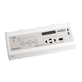
INSTALLATION & SETUP GUIDE FOR THE M2 UNIT CONTROLLER
Use arrows to move
DISPLAY
SERVICE
ALARM
STATUS
OFFLINE
MODE
IN/OUTPUTS
CALLS
REPLACE
USB
REPORT
M2 UNIT CONTROLLER
t Listed
BACnet
R
USB CONNECTION
(for Unit Controller
Description
The Prodigyt M2 unit controller:
S
provides control functions for Energencet roof-
top unit,
S
includes a user interface consisting of a dot ma-
trix display, navigation arrow buttons, a select
button, and a USB port,
S
provides status & diagnostic information for trou-
bleshooting,
S
allows adjustment of time delays and setpoints
that enable advanced features,
S
is controlled by a standard room thermostat, di-
rect digital controller (DDC), or a zone sensor,
S
can be configured as a device on the network
when daisy−chained to the L Connection
work,
S
may be connected to a PC which has been
loaded with Unit Controller software,
S
accepts add−on boards to build variations ac-
cording to application or equipment type.
S
USB verification
09/09
*2P0909*
506215−01
09/09
USED WITH ENERGENCEt ROOFTOP UNITS
Push to select or enter value; then use
arrows
DATA
SETTINGS
TEST
RUNTIMES
UNIT
HISTORY
SETPOINTS
SENSORS
CONTROL
NETWORK
OPTIONS
FACTORY
INSTALL
L CONNECTION ( optional
connection method for Unit
software)
Controller software)
®
DISPLAY
DISPLAY
USER INTERFACE NAVIGATION ARROWS
USER INTERFACE NAVIGATION ARROWS
SMARTWIREt
CONNECTORS
Table Of Contents
M2 unit controller, expansion board locations,
SmartWiret connections
M2 unit controller LED operation indications
Startup
. . . . . . . . . . . . . . . . . . . . . . . . . . . . . . . . . . . . . . . . . . . .
Menu interface
. . . . . . . . . . . . . . . . . . . . . . . . . . . . . . . . . . . . .
Operation:
DISPLAY
. . . . . . . . . . . . . . . . . . . . . . . . . . . . . . . . . . . . . .
SERVICE
. . . . . . . . . . . . . . . . . . . . . . . . . . . . . . . . . . . . . .
TEST
. . . . . . . . . . . . . . . . . . . . . . . . . . . . . . . . . . . . .
DATA
. . . . . . . . . . . . . . . . . . . . . . . . . . . . . . . . . . . . . . . . .
SETTINGS
BACnet ®
. . . . . . . . . . . . . . . . . . . . . . . . . . . . . . . . . . . . . . . . . .
Networking Controllers
Economizer (Damper)
APPENDIX:
Net-
Abbreviations
Parts List
. . . . . . . . . . . . . . . . . . . . . . . . . . . . . . . . . . . . . .
USB Service Report Example
Alarm Codes
Wiring Diagrams
M2 unit controller signal reference diagram
M2 unit controller board connections diagram
QUICK START GUIDE (BACK COVER)
Page 1
PRODIGYt
M2 Unit Controller
USB
USB
INTERFACE
INTERFACE
PORT
PORT
(For Flash Drive
SELECT
SELECT
BUTTON
BUTTON
. . . . . . . . . . . . . . . . . . . . . . . .
. . . . . . . . . . . .
. . . . . . . . . . . . . . . . . . . . . . . . . . . . . . . . . . . .
. . . . . . . . . . . . . . . . . . . . . . . . . . . . . .
. . . . . . . . . . . . . . . . . . . . . . . . . . . . . . .
. . . . . . . . . . . . . . . . . . . . . . . . . . . . . . . . . .
. . . . . . . . . . . . . . . . . . . .
. . . . . . . . . . . . . . . . . . . . . . . . . . . . . . . . . . .
. . . . . . . . . . . . . . . . . . . . . . . . . . . . . . . .
. . . . . . . . . . . .
506215−01
*P506215-01*
2
3
3
5
6
7
8
9
11
15
17
18
20
20
21
22
25
. . . . . . . . .
30
. . . . . . .
31
32
Advertisement

Related Manuals for Lennox PRODIGY M2


Summary of Contents for Lennox PRODIGY M2
- Page 1 PRODIGYt 506215−01 09/09 M2 Unit Controller E2009 Litho U.S.A. INSTALLATION & SETUP GUIDE FOR THE M2 UNIT CONTROLLER USED WITH ENERGENCEt ROOFTOP UNITS DISPLAY DISPLAY Push to select or enter value; then use Use arrows to move arrows INTERFACE INTERFACE PORT DISPLAY SERVICE...
- Page 2 M2 (A55) unit controller − location, controls, inputs/outputs M2 unit controller board, expansion board locations, SmartWiret connections Figure 1 shows the controller components and the locations for expansion boards. CONTROL CONTROL BOARD BOARD EXPANSION EXPANSION PORT PORT ECONOMIZER POTS 2 AMP FUSE USB CONNECTION AND DIP SWITCHES (for Unit Controller...
- Page 3 M2 unit controller LED indicators Some indicators on the circuit board are visible with the cover in place; others are not. The indicators and their meanings are described in table 1. Table 1. LED operation indications Status Indication Meaning Status Indication Meaning S−BUS...
- Page 4 Startup (continued) User interface menu tom of the left column in figure 2. For example, if an alarm is present, that will be displayed until it has been silenced or The user interface is accessed through the menu naviga- cleared. tion arrows and the select button .
- Page 5 Menu Interface Table 2 shows the major levels of the menu interface. Table 2. Menu Interface (cont’d) Many of these options have more levels and are described in the following sections that detail DISPLAY, SERVICE, Level 1 Level 2 Level 3 DATA, and SETTINGS.
- Page 6 Demand satisfied; blower off USB Service Verification MORNING WARMUP Outdoor air damper closed When the Lennox USB drive is plugged in during normal Display is missing messages from M2 FAILED TO RESPOND MODE, a message will be displayed to indicate data is be- ing written to the drive.
- Page 7 Menu Interface SERVICE From the DISPLAY mode, press and then use SERVICE > OFFLINE scroll to SERVICE. Next, press to enter the SERVICE In the SERVICE menu, use until OFFLINE is dis- menu. Use until desired item is displayed. played. Press to enter the OFFLINE menu.
- Page 8 Menu Interface SERVICE (Continued) SERVICE > TEST (Continued) Table 4. TEST TEST GUIDED BLOWER HIGH K3 HK3 OFF/ON Run blower on maximum speed LOW K3 LK3 OFF/ON Run blower on minimum speed PROVING SWITCH Display status of the switch with blower low speed. FILTER SWITCH Display status of the switch with blower low speed XX RPM...
- Page 9 Menu Interface DATA From the DISPLAY mode, press and then use DATA > HISTORY scroll to DATA. Next, press to enter the DATA menu. In the DATA menu, use until HISTORY is displayed. until desired item is displayed. Press to enter the HISTORY menu. Read the accumulated historical data of alarms, status, Use DATA to view information stored in the M2 Unit Con- and USB reports logged by the M2 unit controller.
- Page 10 Menu Interface DATA (Continued) DATA > NETWORK DATA > FACTORY In the DATA menu, use until FACTORY is displayed. In the DATA menu, use until NETWORK is displayed. Press to enter the NETWORK menu. Press to enter the NETWORK menu. Read the FACTORY information stored in the M2 unit con- Read the NETWORK addresses stored in the M2 unit con- troller.
- Page 11 Menu Interface SETTINGS − From the DISPLAY mode, press and then use SETTINGS > SETPOINTS scroll to SETTINGS. Next, press to enter the SET- COOLING TINGS menu. Use until desired item is displayed. HEATING (See Page 12 for DAMPER) Use SETTINGS to make changes to the REHEAT SETTINGS Unit Controller after initial installation.
- Page 12 Menu Interface SETTINGS (Continued) SETTINGS > SETPOINTS SETTINGS > CONTROL DAMPER LOCAL Use SETTINGS > SETPOINTS > DAMPER as shown in Select SETTINGS > CONTROL > LOCAL as shown in the the following diagram; default settings will be used. You following diagram;...
- Page 13 Menu Interface SETTINGS (Continued) SETTINGS > CONTROL SETTINGS > CONTROL BACNET MSAV (Multi-stage air volume) Select SETTINGS > CONTROL > BACNET as shown in Select SETTINGS > CONTROL > MSAV as shown in the the following diagram; default settings will be used. You following diagram;...
- Page 14 Menu Interface SETTINGS (Continued) SETTINGS > INSTALL SETTINGS > INSTALL In the SETTINGS menu, use until INSTALL is dis- INSTALL: NEW M2 played. Press to enter the INSTALL menu. Use SETTINGS > INSTALL > NEW M2 as shown in the Use INSTALL >...
- Page 15 ROUTER Cable type − twisted pair with shield, 22 awg minimum, (terminated) (not terminated) (terminated per mfg Belden #88761 or #8761 (Lennox 27M19, 94L63, 68M25). instructions) Figure 4. Terminating ends of daisy−chained networks Analog Output Objects Optional Properties Supported: Min_Pres_Value, Max_Pres_Value...
- Page 16 ® BACnet (continued) Analog Input Objects Optional Properties Supported: None Optional Writable Properties: Out_Of_Service (AI239 − AI252, AI274 − AI285 only) Table 6. Analog Input Objects List Object ID Object Name Units Data Range Mac Address None 0 − 127 M2 Address None 1−31...
- Page 17 SYS BUS TERMINAL S−BUS TERMINAL BLOCK ON LENNOX BLOCK ON LENNOX BLOCK ON LENNOX CONTROLLERS IMC CONTROLLERS IMC (M1−7, PRODIGY M2 CON- (M1−1 TO M1−6 L M1−8, NTC, BC AND ZONE TROLLER ENER- SERIES) CONTROLLERS) GENCE SERIES − G + −...
- Page 18 Economizer (Damper) General Free Cooling Discharge Air Setpoint When outdoor air conditions are suitable and economizer The economizer, when configured, controls is set to provide free cooling, dampers will modulate to damper position, which determines how much outdoor achieve a discharge air temperature of 55°F (13°C) de- air is used to meet free cooling or indoor air quality fault.
- Page 19 Economizer (Damper) (Continued) Mode Outdoor air is suitable for free cooling when: TEMP OFFSET Outdoor air temperature (RT17) is less than return air temperature (RT16) by at least the OFFSET value. TEMP OAT STPT Outdoor air temperature (RT17) is less than the OAT STPT value. Either of the TEMP modes can be used when a network OAS signal is provided by an energy management or building Remote control system, via BACnet, LonTalk, or L Connection.
- Page 20 59W53 SmartWiret Repair Tool kit 59W58 DB1−1 M2 Display Replacement kit 59W49 M2−1 Fuse (2−Amp ATC, 5−pack) 59W54 Lennox Prodigyt USB Memory 59W59 Stick (5−pack) MCB1 M2 Motor Control Replace- 59W50 M2 Deluxe Training kit (suitcase, 59W55 Service Software & Expert Manual...
- Page 21 USB Service Report Example USB SERVICE REPORT ========================================================================== Service Date 09/10/2009 Service Time 13:22:01 Serial No. SN NOT SET M2 Version 7.00.00 DB1 Version 1.00 Unit No. Unit Address BACnet Address. CAT No. CN NOT SET Description No Description Unit Status COOLING ========================================================================== Runtime Data...
- Page 22 Page 22...
- Page 23 Page 23...
- Page 24 Page 24...
- Page 25 Wiring Diagrams (036, 048, 060 Units) DESCRIPTION COMPONENT MONITOR, PHASE PROTECTION CONTROL, MAIN PANEL LENNOX PANEL, MOTOR CONTROL A169 COMPRESSOR 1 MOTOR, BLOWER MOTOR, OUTDOOR FAN MOTOR, EXHAUST FAN CAPACITOR, COMPRESSOR CAPACITOR, EXHAUST FAN CAPACITOR, COMPRESSOR HARD START CIRCUIT, BREAKER...
- Page 26 ACCESSORIES PLUG, RT6 SUPPLY AIR SENSOR P100 PLUG, SMOKE DETECTOR ONE P250 PLUG, SMOKE DETECTOR ONE P251 PLUG, SMOKE DETECTOR TWO P252 PLUG, SMOKE DETECTOR TWO P253 PLUG, MODULE, CONTROL SMOKE DETECTION P255 PLUG, ECONOMIZER P262 Lennox Commercial Page 26...
- Page 27 Wiring Diagrams (ACCESSORIES) J299A P299 DI−1 USE DI2 TO CONNECT: 1. OVERLOAD CONTACTS DI−2 S135A DI−3 S149 DI−4 USE DI3 TO CONNECT: 1. OVERFLOW SWITCH 2. PHASE MONITOR MODULE P304 A130 TB37 Page 27...
- Page 28 Wiring Diagrams (240, 300 Units) Page 28...
- Page 29 COMPONENT COMPONENT PANEL, MAIN K2,−1 CONTACTOR, COMPRESSOR 2 PANEL, COMPRESSORS 3 AND 4 K3, −1 CONTACTOR, BLOWER COMPRESSOR 1 K10,−1,2 RELAY, OUTDOOR FAN 1 COMPRESSOR 2 K14,−1 CONTACTOR, COMPRESSOR 3 MOTOR, BLOWER K65−1,2 RELAY, EXHAUST FAN MOTOR, OUTDOOR FAN 1 K68,−1 RELAY, OUTDOOR FAN 2 MOTOR, OUTDOOR FAN 2...
- Page 30 Page 30...
- Page 31 P270 DISPLAY PCB Page 31...
- Page 32 (Page 12). Humidity control requires sensor or error code 76 MSAV Change motor torque; see Use LENNOX MSAV trained technician. SETTINGS −> CONTROL −> LOCAL Final motor CFM needs to be set by Test and (Page 13). Balance technician Blower charts are located in unit EHB.
Need help?
Do you have a question about the PRODIGY M2 and is the answer not in the manual?
Questions and answers