Advertisement
©2019 Lennox Industries Inc.
This manual must be left with the
owner for future reference.
WARNING
Improper
installation,
alteration, service or maintenance can
cause property damage, personal injury or
loss of life.
Installation and service must be performed
by a licensed professional HVAC installer
(or equivalent) or service agency.
Specifications
Input voltage
Ambient temperature
Ambient humidity
Dallas, Texas, USA
adjustment,
5 VDC
23~110°F (-5~43°C)
RH40%~RH90%
INSTALLATION/
OPERATION
INSTRUCTIONS
M0STAT64Q-1 Indoor Unit
Programmable
Controller
CONTROLS
507644-02
3/2019
Supersedes 507644-01
IMPORTANT
Frequent changes to operating mode may
cause system malfunction. Allow at least
one minute between mode changes to
allow the system to stabilize.
Shipping and Packing List
Package 1 of 1 contains;
1 – Wired Controller
1 – Lithium battery
3 – Screws (mount to wall)
2 – Screws (mount to J-box)
2 – Plastic spacers (J-box)
1 – Connection Cable A with connector for all
indoor units
1 – Connection Cable B with connector for
MMDA/B, MCFA/B, M22A and M33A/B
indoor units
1 – Connection Cable C with connector for
MWMA/B indoor units
1 – Installation and operation manual
1
Advertisement
Table of Contents

Related Manuals for Lennox M0STAT64Q-1


Summary of Contents for Lennox M0STAT64Q-1
- Page 1 INSTALLATION/ OPERATION INSTRUCTIONS ©2019 Lennox Industries Inc. Dallas, Texas, USA M0STAT64Q-1 Indoor Unit Programmable Controller CONTROLS 507644-02 3/2019 Supersedes 507644-01 IMPORTANT Frequent changes to operating mode may cause system malfunction. Allow at least one minute between mode changes to This manual must be left with the allow the system to stabilize.
-
Page 2: Wiring Connections
Requirements General The M0STAT64Q is a wired programmable local Be sure that power supply has been turned off controller for mini-split indoor units with conve- before beginning installation. This controller nient timed schedules for daily operation. These should be used only as described in this man- instructions are intended as a general guide and ual. - Page 3 IMPORTANT IMPORTANT Read all of the information in this manual be- The provided cables must be used. Do not fore using this controller. All wiring must con- use excessive force while pulling the cable or form to local and national building and elec- when making the connections.
- Page 4 CN 40 Connect to controller Figure 5. M22A and M33A/B Main Board CN 40 Connect to controller Figure 3. MMDA/B Main Board CN 40 Connect to controller Figure 4. MCFA/B Main Board...
- Page 5 Receiver board Cable C Cable A CN403 4-conductor shielded wire on the controller Figure 6. Wiring Connections MWMA/B Factory-connected to CN 403 Display Board Connect to controller NOTE - CN 403 is used to connect either the M0STAT64Q local controller OR a centralized control. It is not possible to connect both the M0STAT64Q controller and a centralized control to this unit.
- Page 6 2. Select the cable exit route from the back of the 5. Reattach the controller to the back plate. Be controller. See figure 8. careful not to pinch or bind the wires. See fig- ure 10. ¹Use snips to notch the controller casing to allow the cable to pass through.
-
Page 7: Installation
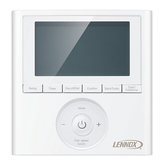
Installation 1. Remove the controller from the back plate us- 3. J-box installation - Adjust the length of the two ing a flat-head screwdriver. See figure 11. plastic spacers as needed to allow the control- ler to be mounted flush with the wall. NOTE –... - Page 8 Display Horizontal and Vertical Swing (not available for all indoor unit models) Faceplate Operation Follow me Speed Function Mode Used Turbo/PTC Function °F or °C ¹Tempera- ture display Lock Indication Room Temperature Clock Schedule On/Off Timer ¹ Displays cooling set point, heating set point or room temperature...
-
Page 9: Description Of Buttons
Description of Buttons Swing but- ton (Swing function not available for all indoor unit Copy/ models) Follow me Copy/ Swing Timer Day o /Del Con rm Back/Turbo Follow me Timer Back/Turbo Day Off/ Confirm Mode Delete Mode Power Decrease Increase Fan speed Fan speed (Lock) - Page 10 Setup Set the Current Day and Time 1. Press and hold the Timer button for 3 sec- onds. 2. Use the + and - buttons to select the day. The selected day will flash. 3. Press the Timer button to complete the date setting.
-
Page 11: Operation
Operation To Start/Stop Operation Turn ON/OFF Turbo Function Press the Power button. Press the Back/Turbo button to activate and de- activate the turbo functionality. To set the operation mode • Cooling Mode - Turbo sets the indoor unit 1. Press the Mode button to set the operation fan speed to high for a factory-set period mode. - Page 12 Timer and Schedules Create Schedules (up to 8 events per day) Use the Timer button to setup Weekly schedules 1. Press the Timer button until Week is high- or to setup timed operation for the indoor unit. lighted. Timers are used to schedule On/Off operation 2.
- Page 13 set to Auto, Dry or Off. 4. Press the Copy/Follow Me button. The letters 10. Follow steps 2 through 9 to setup the next “CY” will be displayed on the screen. event. Each event ends at the start time of 5.
- Page 14 Fan or Off. 12. Use the + and - buttons to change the fan speed for the event. 13. Press the Confirm button to confirm the fan speed and complete the changes for this event. Not available when operation mode is set to Auto, Dry or Off.
-
Page 15: Troubleshooting Fault Codes
Troubleshooting Fault Codes Indoor Unit M0STAT64Q Error Code Description Display Display Communication error between wired controller and indoor unit The cassette faceplate is abnormal Indoor unit EEPROM error Communication error between indoor unit and outdoor units Indoor fan speed error Indoor Return air temperature sensor error Indoor coil temperature sensor error Low refrigerant...
Need help?
Do you have a question about the M0STAT64Q-1 and is the answer not in the manual?
Questions and answers
MOSTAT64Q-1. I manually set "Heat" and adjust accordingly. However, occasionally, it sets to "Auto." How do I correct this.
To stop the Lennox M0STAT64Q-1 thermostat from switching to "Auto" mode when manually set to "Heat", allow at least one minute between mode changes. Frequent or rapid changes can cause the system to malfunction and revert to a default mode like "Auto".
This answer is automatically generated