Table of Contents

Advertisement

• This manual is an integral and essential part of the product. Carefully read the instructions contained
herein as they provide important hints for use and maintenance safety.
• This device shall be used only for the purposes it is aimed at. Any other use is to be considered as
improper and dangerous. The manufacturer is not responsible for any possible damage caused by
improper, erroneous and irrational uses.
• Elettronica Santerno are responsible for the device in its original setting.
• Any changes to the structure or operating cycle of the device must be performed or authorized by
Elettronica Santerno's Engineering Department.
• Elettronica Santerno are not responsible for the consequences resulting from the use of non-original
spare parts.
• Elettronica Santerno reserve the right to make any technical changes to this manual and the device
without prior notice. Any misprint or spelling mistake will be edited in the new versions of this manual.
• Elettronica Santerno are responsible for the information contained in the original version of the Italian
manual.
• The information contained herein is Elettronica Santerno's property and cannot be reproduced.
Elettronica Santerno enforce their rights on the drawings and catalogues according to the law.
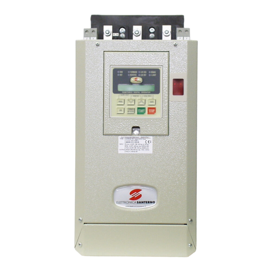
DCREG2
DCREG4
USER MANUAL
28/05/18 R.07
SOFTWARE VERSION D5.02
Elettronica Santerno S.p.A.
Via della Concia, 7 – 40023 Castel Guelfo (BO) Italy
Tel. +39 0542 489711 - Fax +39 0542 489722
santerno.com
• 15P0059B3 •
info@santerno.com
E n g l i s h

Advertisement

Table of Contents
loading

Summary of Contents for Santerno DCREG2 Series

  • Page 1 • Elettronica Santerno are not responsible for the consequences resulting from the use of non-original spare parts. • Elettronica Santerno reserve the right to make any technical changes to this manual and the device without prior notice. Any misprint or spelling mistake will be edited in the new versions of this manual.
  • Page 2: Revision Index

    References to old control boards or to older SW versions than the currently implemented version removed. OTHER MANUALS MENTIONED The following manuals from Elettronica Santerno are mentioned throughout this User Manual: • 16B0301B3 PC-DCREG INTERFACING VIA MODBUS • 16B0221B3 PC-DCREG INTERFACING VIA PROFIBUS-DP •...
  • Page 3: Table Of Contents

    DCREG2 15P0059B3 DCREG4 USER MANUAL TABLE OF CONTENTS REVISION INDEX ............................2 OTHER MANUALS MENTIONED ........................ 2 TABLE OF CONTENTS..........................3 DELIVERY CHECK ..........................9 NAMEPLATE ..........................9 TRANSPORT AND HANDLING ....................10 UNPACKING ..........................11 START-UP ............................13 INTRODUCTION ........................13 PRELIMINARY CHECKS ......................
  • Page 4 DCREG2 15P0059B3 DCREG4 USER MANUAL KEYS OPERATING MODES ....................74 FUNCTIONS DISPLAYED BY THE LEDS ................76 LOCAL OPERATING MODE..................... 77 REMOING THE KEYPAD ......................78 FIRMWARE STRUCTURE ........................ 81 GENERAL ..........................81 BLOCK DIAGRAM ........................82 PARAMETER COPY ......................... 91 SPECIAL FEATURES ........................
  • Page 5 DCREG2 15P0059B3 DCREG4 USER MANUAL 7.1.32 M031: Digital Input State from Bus Field ................ 131 PROGRAMMING PARAMETERS ................... 132 7.2.1 P000: Programming P/N ..................... 132 7.2.2 P001: Autotuning Command ....................132 7.2.3 P002: Parameter Copy Command ..................133 7.2.4 P003: Programming Level ....................133 7.2.5 P004: Page Displayed at Power on ..................
  • Page 6 DCREG2 15P0059B3 DCREG4 USER MANUAL 7.2.61 P124: Current Main Input Bias ..................151 7.2.62 P125: Current Main Input Gain ..................151 7.2.63 P126(129)(132): Polarity for Auxiliary Analog Input 1(2)(3 ..........152 7.2.64 P127(130)(133): Auxiliary Analog Input 1(2)(3) Bias ............152 7.2.65 P128(131)(134): Auxiliary Analog Input 1(2)(3) Gain .............
  • Page 7 DCREG2 15P0059B3 DCREG4 USER MANUAL 7.3.38 C143: Alarm A028 Trip Delay ..................180 7.3.39 C150: Alarm A001 Trip Disabling ................... 180 7.3.40 C151: Alarm A004 Trip Disabling ................... 180 7.3.41 C153: Alarm A006 Trip Disabling ................... 180 7.3.42 C154: Alarm A007 Trip Disabling ................... 181 7.3.43 C155: Alarm A008 Trip Management ................
  • Page 8 DCREG2 15P0059B3 DCREG4 USER MANUAL USER’S PARAMETERS DIFFERENT FROM DEFAULT VALUES ..........197 8/200...
  • Page 9: Delivery Check

    The device is called DCREG4.350. It is an AC/DC digital-operated drive. The device main P/N and size P/N are detailed before and after a full stop respectively (ELETTRONICA SANTERNO P/Ns). The acronym identifies the configuration consisting of two full-control three-phase bridges in antiparallel forming the drive power section.
  • Page 10: Transport And Handling

    DCREG2 15P0059B3 DCREG4 USER MANUAL TRANSPORT AND HANDLING The DCREG packing ensures easy and safe handling. Handling shall be done using a transpallet or a lift truck with adequate carrying capacity, in order not to damage the product. Figure 1: Lifting the packing from underneath 10/200...
  • Page 11: Unpacking

    DCREG2 15P0059B3 DCREG4 USER MANUAL UNPACKING Get near the installation place, then unpack following the instructions provided below. 1. Cut with pincers the plastic straps that fix the package of the DCREG to the pallet. 2. Cut with a cutter the adhesive tape closing the box on the side where the package orientation symbol is reproduced (see Figure 3).
  • Page 12 DCREG2 15P0059B3 DCREG4 USER MANUAL Figure 4: The DCREG is unpacked 4. Put all the packing elements in the box and store it in a dry environment. Figure 5: DCREG packing box with the internal protective elements 12/200...
  • Page 13: Start-Up

    DCREG2 15P0059B3 DCREG4 USER MANUAL START-UP INTRODUCTION This section describes the main checks and operations which should be carried out to achieve an excellent adjusting of the DCREG drive. All information contained herein is directed to the Users being already familiar with the use of the keypad. If need be, refer to the KEYPAD AND ALPHANUMERIC DISPLAY section for further information.
  • Page 14: Scheduled Maintenance

    The cooling fans in the DCREG build up dust from air intake. Check if the heatsink is clean. If the heatsink needs to be cleaned, please contact Elettronica Santerno Customer Service. Cooling fans The minimum expected durability of the cooling fans of the DCREG is approx. 50,000 hours. Actual lifetime is based on the operating conditions of the converter, the ambient temperature and the environmental pollution.
  • Page 15: Main Checks And Configurations

    DCREG2 15P0059B3 DCREG4 USER MANUAL MAIN CHECKS AND CONFIGURATIONS 2.4.1 Supply the control section and the field regulator of the device (except the power section). The four LEDs which can be seen through the small rectangular slot on the cover should be off. Whenever the display shows an alarm condition, it is necessary to reset it by simultaneously pressing the “PROG”...
  • Page 16 DCREG2 15P0059B3 DCREG4 USER MANUAL 2.4.4 The device is already supplying the motor field winding, according to the economy function (Field Economy) set in par. C014. On parameter C010 (default value: 10%), set the field rated current percentage of the motor with respect to the field rated current of the drive.
  • Page 17: Speed Control Mode Operation

    DCREG2 15P0059B3 DCREG4 USER MANUAL 2.4.12 Should the feedback be generated from an enP/Nr, check that the transduction ratio of the supplied signal, which has been set on parameter C072 (default value: 1024 pulses/rev) is correct. If necessary, change it accordingly. The speed concerning the maximum reference (expressed in r.p.m.) should always be set on parameter P010 (default value: 2500RPM).
  • Page 18: Ramp Configuration In Speed Control Mode

    DCREG2 15P0059B3 DCREG4 USER MANUAL Make sure that, at maximum speed and maximum voltage, the output ATTENTION armature voltage does not exceed the motor rated value. The operation stability is generally more critical when the speed maximum value being set according to the maximum reference decreases. In order to set maximum speed values being especially low, it is therefore NOTE recommended to reduce the reference amplification through the Gain function...
  • Page 19 DCREG2 15P0059B3 DCREG4 USER MANUAL If the LOC SEQ LED is on or flashing, polarity may also be reversed by pressing the “REVERSE” key. The internal reference, resulting from the application of the operators above, is displayed by par. M014, M010, M011 and M012 respectively.
  • Page 20: Current (Torque) Control Mode Operation

    DCREG2 15P0059B3 DCREG4 USER MANUAL CURRENT (TORQUE) CONTROL MODE OPERATION 2.8.1 A current control (torque) is generally required when tension controls are performed on a winding or unwinding material or while controlling any machine integral to another from a mechanical point of view. In fact, said conditions require a proper torque distribution.
  • Page 21: Current Limit Control Options

    DCREG2 15P0059B3 DCREG4 USER MANUAL CURRENT LIMIT CONTROL OPTIONS 2.9.1 In the speed and current control, the current internal limitation remains always activated. It is generally set as single-value adjusting through parameter P050 and parameter P051 (default values: 100%) and always represents a percentage of the armature current rated value indicated by parameter C000 (default value: 100%).
  • Page 22: 2.11 Backup And Restoration Of Stored Parameters

    DCREG2 15P0059B3 DCREG4 USER MANUAL 2.11 BACKUP AND RESTORATION OF STORED PARAMETERS 2.11.1 After starting the device and checking its correct settings, it is recommended that the user writes down the parameters that have been changed (and stored) with respect to their default values. To do so, use the special table specified on the last pages of the OPERATION MANUAL, in chapter USER’S PARAMETERS CHANGED WITH RESPECT TO DEFAULT VALUES.
  • Page 23: General Characteristics

    DCREG2 15P0059B3 DCREG4 USER MANUAL GENERAL CHARACTERISTICS GENERAL DESCRIPTION APPLICATION The devices of the DCREG series are AC/DC drives with fully digital control system. They fit the armature and field supply of direct current motors to enable the speed or torque control. DCREG4 operates in four quadrants, while DCREG2 operates in two quadrants.
  • Page 24 DCREG2 15P0059B3 DCREG4 USER MANUAL OPERATING FEATURES DCREG4: operation and total reversibility in the four quadrants: may operate as a motor or a brake towards both directions of rotation. Speed or torque control system. DCREG2: operation as motor in the 1st quadrant with speed or torque control system.
  • Page 25 DCREG2 15P0059B3 DCREG4 USER MANUAL ANALOG OUTPUTS No. 2 configurable analog outputs, 12-bit resolution. Possibility of application of Bias, Gain, Polarity operators. V Out voltage signal proportional to the motor running speed. I Out current signal proportional to the supplied armature current (double polarity or positive single polarity only).
  • Page 26 DCREG2 15P0059B3 DCREG4 USER MANUAL From speed feedback failure: alarm A008. From automatic tuning failure: alarms A011, A014, A015, A018 and A019. From general external failure: alarm A020, A029 and A030. From EEPROM failure: alarms A024, A025, A026 and A031. From serial communication failure: alarm A027.
  • Page 27 DCREG2 15P0059B3 DCREG4 USER MANUAL WEIGHT Size 1: 13 kg for DCREG.10 … 40 14 kg for DCREG.70 15 kg for DCREG.100 … 180 18 kg for DCREG2.250 … 350 19 kg for DCREG4. 250 … 350 Size 2: 45 kg for DCREG2 except for: 38 kg for DCREG2.410 ...
  • Page 28: Ratings

    DCREG4.1200 3T/80 3T/80 By request, Elettronica Santerno can provide drives of any size with a field rated NOTE current different than the standard value, which is 5A for DCREG.100max, 15A for DCREG.150min Size 1 and 35A for DCREG Size 2, 2A and MODULAR.S...
  • Page 29 13500 988x543x2070 (Size K) DCREG4.4500S By request, Elettronica Santerno can provide drives of any size with a field rated NOTE current different than the standard value, which is 5A for DCREG.100max, 15A for DCREG.150min Size 1 and 35A for DCREG Size 2, 2A and MODULAR.S...
  • Page 30 13500 988x543x2070 (Size K) DCREG4.4500S By request, Elettronica Santerno can provide drives of any size with a field rated NOTE current different than the standard value, which is 5A for DCREG.100max, 15A for DCREG.150min Size 1 and 35A for DCREG Size 2, 2A and MODULAR.S...
  • Page 31 13500 988x543x2070 (Size K) DCREG4.4500S By request, Elettronica Santerno can provide drives of any size with a field rated NOTE current different than the standard value, which is 5A for DCREG.100max, 15A for DCREG.150min Size 1 and 35A for DCREG Size 2, 2A and MODULAR.S...
  • Page 32 DCREG2 15P0059B3 DCREG4 USER MANUAL OVERLOAD CAPACITY Repetitive overload cycle, I = K • I for 1m and I = I for 9m @ T = 40°C (room temperature), available after operating at a motor current (programmable with par. C000) lower than or equal to rated armature current for a time long enough thus allowing reaching thermal balance.
  • Page 33: Dcreg Size 1 Overall Dimensions

    DCREG2 15P0059B3 DCREG4 USER MANUAL DCREG SIZE 1 OVERALL DIMENSIONS 33/200...
  • Page 34: Dcreg Size 1 Through-Panel Assembly

    DCREG2 15P0059B3 DCREG4 USER MANUAL DCREG SIZE 1 THROUGH-PANEL ASSEMBLY 1 - Direction of the cooling air flow 2 - Fixing panel 3 - Slot to be made in the fixing panel 4 - Through-panel assembly kit parts 34/200...
  • Page 35: Dcreg Size 2 Overall Dimensions

    DCREG2 15P0059B3 DCREG4 USER MANUAL DCREG SIZE 2 OVERALL DIMENSIONS 35/200...
  • Page 36: Dcreg Size 2A Overall Dimensions

    DCREG2 15P0059B3 DCREG4 USER MANUAL DCREG SIZE 2A OVERALL DIMENSIONS 36/200...
  • Page 37: Dcreg Size 2 And Size 2A Through-Panel Assembly

    DCREG2 15P0059B3 DCREG4 USER MANUAL DCREG SIZE 2 AND SIZE 2A THROUGH -PANEL ASSEMBLY - Size 2 1 - Direction of the secondary cooling air flow 2 - Direction of the main cooling air flow 3 - Fixing panel 4 - Slot to be made in the fixing panel - Size 2A 37/200...
  • Page 38: Dcreg Modular.s Size A Power Section Overall Dimensions

    DCREG2 15P0059B3 DCREG4 USER MANUAL DCREG MODULAR.S SIZE A POWER SECTION OVERALL DIMENSIONS 38/200...
  • Page 39: Dcreg Modular.s Size B Power Section Overall Dimensions

    DCREG2 15P0059B3 DCREG4 USER MANUAL DCREG MODULAR.S SIZE B POWER SECTION OVERALL DIMENSIONS 39/200...
  • Page 40: Dcreg Modular.s Size C Power Section Overall Dimensions

    DCREG2 15P0059B3 DCREG4 USER MANUAL 3.10 DCREG MODULAR.S SIZE C POWER SECTION OVERALL DIMENSIONS 40/200...
  • Page 41: Dcreg Modular.s Size D Power Section Overall Dimensions

    DCREG2 15P0059B3 DCREG4 USER MANUAL 3.11 DCREG MODULAR.S SIZE D POWER SECTION OVERALL DIMENSIONS 41/200...
  • Page 42: Dcreg Modular.s Size E Power Section Overall Dimensions

    DCREG2 15P0059B3 DCREG4 USER MANUAL 3.12 DCREG MODULAR.S SIZE E POWER SECTION OVERALL DIMENSIONS 42/200...
  • Page 43: Dcreg Modular.s Size F Power Section Overall Dimensions

    DCREG2 15P0059B3 DCREG4 USER MANUAL 3.13 DCREG MODULAR.S SIZE F POWER SECTION OVERALL DIMENSIONS 43/200...
  • Page 44: Dcreg Modular.s Size G Power Section Overall Dimensions

    DCREG2 15P0059B3 DCREG4 USER MANUAL 3.14 DCREG MODULAR.S SIZE G POWER SECTION OVERALL DIMENSIONS 44/200...
  • Page 45: Dcreg Modular.s Size H Power Section Overall Dimensions

    DCREG2 15P0059B3 DCREG4 USER MANUAL 3.15 DCREG MODULAR.S SIZE H POWER SECTION OVERALL DIMENSIONS 45/200...
  • Page 46: Dcreg Modular.s Size I Power Section Overall Dimensions

    DCREG2 15P0059B3 DCREG4 USER MANUAL 3.16 DCREG MODULAR.S SIZE I POWER SECTION OVERALL DIMENSIONS 46/200...
  • Page 47: Dcreg Modular.s Size J Power Section Overall Dimensions

    DCREG2 15P0059B3 DCREG4 USER MANUAL 3.17 DCREG MODULAR.S SIZE J POWER SECTION OVERALL DIMENSIONS 47/200...
  • Page 48: Dcreg Modular.s Size K Power Section Overall Dimensions

    DCREG2 15P0059B3 DCREG4 USER MANUAL 3.18 DCREG MODULAR.S SIZE K POWER SECTION OVERALL DIMENSIONS 48/200...
  • Page 49: Dcreg Modular.s Size L Power Section Overall Dimensions

    DCREG2 15P0059B3 DCREG4 USER MANUAL 3.19 DCREG MODULAR.S SIZE L POWER SECTION OVERALL DIMENSIONS 49/200...
  • Page 50: Dcreg Modular.s Control Unit Overall Dimensions

    DCREG2 15P0059B3 DCREG4 USER MANUAL 3.20 DCREG MODULAR.S CONTROL UNIT OVERALL DIMENSIONS 50/200...
  • Page 51: Dcreg Size 1

    DCREG2 15P0059B3 DCREG4 USER MANUAL 3.21 DCREG SIZE 1...2A POWER CONNECTIONS VALID FOR DCREG SIZE1...2A FOR MAINS UP TO 500 Vac 51/200...
  • Page 52 DCREG2 15P0059B3 DCREG4 USER MANUAL VALID FOR DCREG SIZE 1...2A FOR MAINS EXCEEDING 500 Vac 52/200...
  • Page 53: 3.22 Dcreg Modular.s Power Connections

    DCREG2 15P0059B3 DCREG4 USER MANUAL 3.22 DCREG MODULAR.S POWER CONNECTIONS VALID FOR DCREG MODULAR.S FOR MAINS UP TO 500 Vac (*) VEDI NOTA (SEE NOTE) NOTE (*) Supply term. 53-54 with AC voltage OR term. 44-42 with DC voltage. 53/200...
  • Page 54 DCREG2 15P0059B3 DCREG4 USER MANUAL VALID FOR DCREG MODULAR.S FOR MAINS EXCEEDING 500 Vac (*) VEDI NOTA (SEE NOTE) NOTE (*) Supply term. 53-54 with AC voltage OR term. 44-42 with DC voltage. 54/200...
  • Page 55: 3.23 Dcreg Modular.s Power Unit Wiring Diagram

    DCREG2 15P0059B3 DCREG4 USER MANUAL 3.23 DCREG MODULAR.S POWER UNIT WIRING DIAGRAM NOTE TH1B ... 6B thyristors (4 quadrants operation) in DCREG4 only. 55/200...
  • Page 56: 3.24 Dcreg Modular.s Control Unit Terminals

    DCREG2 15P0059B3 DCREG4 USER MANUAL 3.24 DCREG MODULAR.S CONTROL UNIT TERMINALS Decisive voltage class C according to EN 61800-5-1 A bridge TH1 thyristor gate (to terminal G1A of the Control Unit) A bridge TH1 thyristor cathode (to terminal K1A of the Control Unit) A bridge TH2 thyristor gate (to terminal G2A of the Control Unit) A bridge TH2 thyristor cathode...
  • Page 57: 3.25 Supply And Power Terminals

    DCREG2 15P0059B3 DCREG4 USER MANUAL 3.25 SUPPLY AND POWER TERMINALS Terminal Description Notes Decisive voltage class C according to EN 61800-5-1 Standard 440 Vac max Electrical connection: DCREG Size 1: 3xM8 (screw torque: 16 Nm / 142 lb/in) Input bars for armature rectifier DCREG Size 2: 3xM10 (screw torque: 25 Nm / 221 lb/in) three-phase bridge power supply.
  • Page 58 If the control section is to be supplied with a single-phase alternating voltage, the max. voltage to be applied to terminals 53-54 is 500 Vac. For the mains up to 690 Vac, ELETTRONICA SANTERNO may supply a single-phase, 700/500 V transformer, 150 VA, P/N TR0112260.
  • Page 59: 3.26 Legend For Power Connections

    L1-2-3 50/60 Hz three-phase mains. Direct current motor (armature circuit + field circuit). DCREG MODULAR.S power unit. Three-phase 50VA 700/500V transformer: phase shift 0°. ELETTRONICA SANTERNO P/N: TR0108007. N.B.: This is required for power supply values exceeding 500 Vac. 59/200...
  • Page 60 DCREG2 15P0059B3 DCREG4 USER MANUAL Whenever requested, it is recommended to use ULTRAFAST FUSES of NOTE the same type and value indicated in the RATINGS tables, so as to avoid possible damages of the converter. Always install a three-phase remote control switch on the A.C. side, together with a suitable NO auxiliary contact directly in the terminal 24 (ENABLE) series, as indicated in the SIGNAL CONNECTIONS diagram.
  • Page 61: Cross-Sections Of The Power Cables And Sizes Of The Protective Devices

    500 Vac. A 1000 Vac cable is required above CAUTION 500 Vac (below 600 Vac). The power cables must be rated for 75 °C (167 °F). NOTE For details on wiring and safety devices for a DCREG MODULAR.S please contact Elettronica Santerno. 61/200...
  • Page 62: 3.28 Switching Three-Phase Inductance

    DCREG2 15P0059B3 DCREG4 USER MANUAL 3.28 SWITCHING THREE-PHASE INDUCTANCE A three-phase inductance is to be inserted into the power supply line. The inductance is aimed at: - Reducing the mains voltage distortions from the sinusoidal form in the drive connecting point. - Reducing the line current gradients which may cause both radio interferences and induced interferences in the close lines.
  • Page 63: 3.29 Ul-Approved Fuses

    DCREG2 15P0059B3 DCREG4 USER MANUAL 3.29 UL-APPROVED FUSES UL-approved semiconductor R/C Special purpose fuses which are recommended for the DCREG drives, are listed in the table below. In multiple cable installations, install one fuse per phase (NOT one fuse per conductor). Fuses suitable for the protection of semiconductors produced by other manufacturers may be used, provided that: •...
  • Page 64: 3.30 Short-Circuit Current

    DCREG2 15P0059B3 DCREG4 USER MANUAL 3.30 SHORT-CIRCUIT CURRENT The Short Circuit Current is referred to the maximum converter power. All the converter models are rated for Standard Fault Current values in accordance with UL508C and based on an Internal Solid State Short Circuit protection whose operation and whose manufacturing process complies with UL508C.
  • Page 65: 3.31 Converter And Motor Ground Connection

    DCREG2 15P0059B3 DCREG4 USER MANUAL 3.31 CONVERTER AND MOTOR GROUND CONNECTION A bolted screw for the converter enclosure grounding is located close to the power wiring terminals. The grounding screw is identified by the symbol below: Always ground the DCREG to a state-of-the-art mains. To reduce disturbance and radiated interference to a minimum, connect the motor grounding conductor directly to the DCREG following a parallel path to the motor supply cables.
  • Page 66: 3.32 Dcreg Signal Connections

    DCREG2 15P0059B3 DCREG4 USER MANUAL 3.32 DCREG SIGNAL CONNECTIONS DCREG2: standard usage, supply the potentiometer between term. 1 and 2 66/200...
  • Page 67: 3.33 Signal Terminals

    DCREG2 15P0059B3 DCREG4 USER MANUAL 3.33 SIGNAL TERMINALS Decisive voltage class A according to EN 61800-5-1 (except for the cases specified below) TERM. Description I/O Ratings +10 Vdc / 10 mA max +10V: +10V reference voltage output for analog inputs. 0V: Zerovolt.
  • Page 68 DCREG2 15P0059B3 DCREG4 USER MANUAL TERM. Description I/O Ratings CH N: Zero position pulse of the enP/Nr. 102.4 k Hz max CH A: Channel A of the enP/Nr. +5 Vdc +5V: +5V mains supply voltage for the enP/Nr. It is optoinsulated from the 0V 160 mA max signal of analog inputs.
  • Page 69 DCREG2 15P0059B3 DCREG4 USER MANUAL TERM. Description I/O Ratings Iin  9 mA MDI 5: Digital input 5 to be configured through parameter C134 (MDI5Cfg). Default configuration: 4:Clim. 37-39 MDO 4: Digital output 4 to be configured through parameter P188 (MDO4Cfg). 5A / 250 Vac 5A / 30 Vdc Default configuration: 5:Drive Running.
  • Page 70: 3.34 Leds And Test Points On The Control Board

    DCREG2 15P0059B3 DCREG4 USER MANUAL 3.34 LEDS AND TEST POINTS ON THE CONTROL BOARD The following is a list of visual indications provided by the LEDs installed on the control board. The voltage values of the test points on the same board are also stated. LEDs: (green) heatsink switch closed...
  • Page 71: 3.35 Feedback From Enp/Nr

    In that way, the ground potential on 90° female connector in the control board will be transmitted to the metal body, then to the screened cable shield connecting the enP/Nr. The connector body is supplied by ELETTRONICA SANTERNO (P/N CN0420000), as well as 9-pole D- connector (P/N CN0400018).
  • Page 72: 3.36 Milliampere Input / Output Signals

    DCREG2 15P0059B3 DCREG4 USER MANUAL 3.36 MILLIAMPERE INPUT / OUTPUT SIGNALS It is possible to feed an analog input as an mA signal to terminals 5 / 7 (REF) or terminals 11 / 13 (IN 1): if current enters terminal 5 and goes out from terminal 7, or if current enters terminal 11 and goes out from terminal 13, the internally generated signal is positive by default.
  • Page 73 DCREG2 15P0059B3 DCREG4 USER MANUAL Between signal AnOut1(2) in Volt, which is internally generated after configuring analog output OUT 1 or OUT 2 as desired and which is displayed by parameters M019 and M020 respectively, and outgoing signal in mA, the following relation is to be applied: AnOut1(2)=10V ...
  • Page 74: Keypad And Alphanumeric Display

    DCREG2 15P0059B3 DCREG4 USER MANUAL KEYPAD AND ALPHANUMERIC DISPLAY KEYS OPERATING MODES The drives of the DCREG2 and DCREG4 Series may be equipped with a remotable keypad provided with an alphanumeric display, including 8 keys and 8 signalling LEDs. The keypad is not series installed on the drive and is to be delivered NOTE separately.
  • Page 75 DCREG2 15P0059B3 DCREG4 USER MANUAL - “JOG”: is active only when at least one of the sources selected for the commands corresponds to KeyPad and, when depressed, it enables the jog mode with a reference equal to the one obtained by enabling digital input JogA.
  • Page 76: Functions Displayed By The Leds

    DCREG2 15P0059B3 DCREG4 USER MANUAL The diagram below shows the sequence of the pages displayed through the MONITOR function (the “  ” and “  ” keys are simultaneously pressed). For a better understanding, let us suppose to start from the page relating to par.
  • Page 77: Local Operating Mode

    DCREG2 15P0059B3 DCREG4 USER MANUAL The LOC REF LED is on if the sources selected for the references are UpDownRef-related only, it flashes if another source different than UpDownRef is selected, while it is off if none of the sources selected for the references is UpDownRef-related.
  • Page 78: Remoing The Keypad

    DCREG2 15P0059B3 DCREG4 USER MANUAL REMOING THE KEYPAD The keypad remote control kit includes the following: N.1 panel-front frame. N.1 stick-on rubber gasket. N.1 RJ45 extension cord (L = 5m). N.4 M3 self-locking nuts. N.4 M3 flat washers. To remove the keypad from the drive and to install it on a control panel front, follow the instructions below. If the keypad is not installed on the equipment (standard supply), ignore steps c, d, e.
  • Page 79 DCREG2 15P0059B3 DCREG4 USER MANUAL The keypad is removed. Extract the wire by pressing on the connector tab. Insert the keypad frame again. Fasten with the proper screw. Connect an end of the keypad extension cord to the connector installed on the DCREG. Insert the other end of the cord in the connector installed on the keypad rear part.
  • Page 80 DCREG2 15P0059B3 DCREG4 USER MANUAL Make the panel holes for the frame assembly. Fasten the keypad using the nuts and flat washers supplied with the kit. 80/200...
  • Page 81: Firmware Structure

    DCREG2 15P0059B3 DCREG4 USER MANUAL FIRMWARE STRUCTURE GENERAL The drive control firmware is to be found in FLASH U20 of the control board; its software version (Dx.xx) is displayed by the Status page, whereas the user’s parameters may be saved on EEPROM U11 in the same board.
  • Page 82: Block Diagram

    DCREG2 15P0059B3 DCREG4 USER MANUAL BLOCK DIAGRAM 82/200...
  • Page 83 DCREG2 15P0059B3 DCREG4 USER MANUAL 1 - Main Ref 83/200...
  • Page 84 DCREG2 15P0059B3 DCREG4 USER MANUAL 2 - Ref n 84/200...
  • Page 85 DCREG2 15P0059B3 DCREG4 USER MANUAL 3 - Voltage loop 85/200...
  • Page 86 DCREG2 15P0059B3 DCREG4 USER MANUAL 4- I Ref 86/200...
  • Page 87 DCREG2 15P0059B3 DCREG4 USER MANUAL 5 - Current loop 87/200...
  • Page 88 DCREG2 15P0059B3 DCREG4 USER MANUAL 6 - Field loop 88/200...
  • Page 89 DCREG2 15P0059B3 DCREG4 USER MANUAL 7 - Analog In/Out 89/200...
  • Page 90 DCREG2 15P0059B3 DCREG4 USER MANUAL 8 - Digital In/Out 90/200...
  • Page 91: Parameter Copy

    Step 3 typically takes place when the drive is turned on. In steps 4 and 5, the parameter original values may be retrieved following the given instructions. For steps 1 and 2, contact ELETTRONICA SANTERNO. For a better understanding of the meaning of the different alarms or warnings, please refer to ALARM PARAMETERS and WARNING PARAMETERS chapters.
  • Page 92 DCREG2 15P0059B3 DCREG4 USER MANUAL The parameters may be copied by the user as follows. 1. Default parameter restoration. To restore the default parameters, set par.P002 (ParmsCopy) at 1:DefaultRestore and press the “SAVE” key twice. The user’s customized parameters are erased, and the factory settings for parameters Pxxx and Cxxx will be reset in EEPROM work area (except the internal data, that cannot be accessed by the user).
  • Page 93: Special Features

    DCREG2 15P0059B3 DCREG4 USER MANUAL SPECIAL FEATURES AUTOTUNING The drives of the DCREG2 and DCREG4 series are provided with a particular operating mode, which is able to recognize the essential characteristics of the motor and load as well, in order to automatically calculate the optimal parameters to be inserted into the current and speed loops.
  • Page 94 DCREG2 15P0059B3 DCREG4 USER MANUAL 2. Speed autotuning. This tuning can be performed for whichever choice of current loop operation and is generally recommended. It can be avoided in case of a DCREG2, of a DCREG4 in armature feedback or when the inertia torque of the load is variable (i.e.
  • Page 95: Ramps Over The Reference

    DCREG2 15P0059B3 DCREG4 USER MANUAL RAMPS OVER THE REFERENCE In parameters ranging from P030 to P039, the operator may program the ramp application to the set reference in order to produce a reference with no value instant variation (discontinuity). With respect to the references applied when the START input is on, the programmable rise and/or fall ramps are separate concerning the positive polarity and the negative polarity of the set reference (P030 ...
  • Page 96: Motor Potentiometer

    DCREG2 15P0059B3 DCREG4 USER MANUAL MOTOR POTENTIOMETER This function allows to use an internal variable as a reference, that can be increased or decreased using a digital input Up and a digital input Down or using the arrow keys. 1. Reference. At least one of the sources selected for the reference through parameters C105 … C108 (RefSelx) must correspond to UpDownRef;...
  • Page 97: Current Limitation

    DCREG2 15P0059B3 DCREG4 USER MANUAL CURRENT LIMITATION The parameters ranging from P050 to P062 variably control the max. current to be supplied to the load. The figure below shows a possible programming for current limit I lim A(B) depending on speed n and resulting from the combination of the different configuring modes.
  • Page 98 DCREG2 15P0059B3 DCREG4 USER MANUAL For a better understating, c and n values obtained under such conditions are shown below:           The operator may also program P057 = 100%, so that the hyperbolic step ends with P010 max. speed. When the current limit is defined by overlapping two of the modes above or all the modes above, then the current limit enabled time after time will be the lower one among the limits relating to each of the modes applied.
  • Page 99: Operation Quadrants

    DCREG2 15P0059B3 DCREG4 USER MANUAL OPERATION QUADRANTS The operation quadrants are defined in Cartesian coordinates with speed (n) / torque (T). The “forward” direction is associated with positive speeds (feedback polarity); bridge “A” is the one which causes motor clockwise rotation (seen sideways in the drawing) with no external torque. The four quadrants may be identified as follows: 1st Quadrant: Forward direction with motor torque (positive speed feedback and bridge A on).
  • Page 100 DCREG2 15P0059B3 DCREG4 USER MANUAL The figure below shows all operating features of drive DCREG2. Any equipment for the control of a motor may perform either a speed or a torque control. In the four cases below, DCREG2 is used to motorize a winder, an unwinder or an elevator. The driving motor (if any) is supposed to be controlled by an external device.
  • Page 101 DCREG2 15P0059B3 DCREG4 USER MANUAL 101/200...
  • Page 102: Motor Heating Thermal Image

    DCREG2 15P0059B3 DCREG4 USER MANUAL MOTOR HEATING THERMAL IMAGE DCREG converter’s software is able to detect the motor rise in temperature. A motor heating, i.e. the rise  T(t) = T(t) – T in temperature with respect to ambient temperature of a motor supplied with constant current I , follows a curve...
  • Page 103: Field Regulator

    DCREG2 15P0059B3 DCREG4 USER MANUAL FIELD REGULATOR DCREG2 and DCREG4 drives are equipped with an internal field regulator that may be used both to set a field current fixed value and for a dynamic regulation in field weakening mode. In both cases, the field current reference displayed in par. M017 (RefFld), so the relevant current, may be assigned the values shown in the figure below.
  • Page 104 DCREG2 15P0059B3 DCREG4 USER MANUAL In order to enable this operating mode, the drive starts decreasing the field current when the speed required increases, so that the back-electromotive force does not exceed the nominal value. Suppose the motor ratings are the following as far as the field weakening is concerned: Nominal armature voltage 400V Nominal field voltage...
  • Page 105 DCREG2 15P0059B3 DCREG4 USER MANUAL The value set in par. C016 (IfldMinLim) represents the min. limit for the field current provided that the drive is running. We recommend that this limit be never set below the min. current that the regulator will actually retrieve.
  • Page 106: Configurable Digital Outputs

    DCREG2 15P0059B3 DCREG4 USER MANUAL CONFIGURABLE DIGITAL OUTPUTS DCREG drive is provided with 5 digital outputs (relay normally open contact). Any output may be assigned to some configurations: for further details, see the chapter relating to par. P170(176)(182)(188)(194) and to the others chapters relating to the configurable digital outputs. Depending on the configuration assigned, every output enables either when a certain logic condition occurs (e.g.
  • Page 107 DCREG2 15P0059B3 DCREG4 USER MANUAL 107/200...
  • Page 108: Adaptive Speed Parameters

    DCREG2 15P0059B3 DCREG4 USER MANUAL ADAPTIVE SPEED PARAMETERS 6 . 9 When the speed reference value is suddenly changed and the load speed is not able to follow such variation, the speed loop proportional gain in the transient is to be large enough to avoid any excessive speed overshot both during acceleration and deceleration.
  • Page 109 DCREG2 15P0059B3 DCREG4 USER MANUAL 2. Constant-reference quick load change. This may happen in a machine-tool rotating at a constant speed when it starts a piece processing. In that case, to avoid any speed decrease at the beginning of the transient, the proportional gain is to be temporarily increased and the integral time is to be shorter, as shown in the figure below.
  • Page 110: 6.10 Electromagnets Application

    DCREG2 15P0059B3 DCREG4 USER MANUAL 6.10 ELECTROMAGNETS APPLICATION 6.10.1 D RIVE OW ER ONNECTIONS ROTECTING EVICES DCREG converter can be used to power very inductive loads, such as electromagnets. Applications problems due to this type of load - that can be compared to an ohmic resistance series- connected to a very strong inductance - have been solved by a control algorithm specially developed.
  • Page 111 DCREG2 15P0059B3 DCREG4 USER MANUAL EM: Electromagnet FU1-2-3: Ultrafast fuses L: Switching reactance FUC: Fuses 50A gG(gL) DCREG4 FU1-2-3 FIG. 1 Otherwise, if you suppose that over voltage occurs only when the conduction mesh opens on mains side (3-phase supply voltage L1-2-3 derived from sliding brushes), another protective measure exists. On mains side, install an autotransformer (see Fig.
  • Page 112 DCREG2 15P0059B3 DCREG4 USER MANUAL Finally, a third protective measure consists in using only a switching reactance on mains side (switching reactance is shown in Fig. 3). This is the cheapest solution, but no protection is ensured, because no closing link of the magnet current is provided in case of power failure or output wire failure.
  • Page 113: Dcreg4 Electromechanical Diagram For Reference Switching

    DCREG2 15P0059B3 DCREG4 USER MANUAL 6.10.2 DCREG4 E LECTROMECHANICAL IAGRAM EFERENCE W ITCHING The diagram in Figure 4 illustrates how commands and references are managed both for magnetization/demagnetisation and for counter-energizing, which is essential to suppress residual magnetization. If relays are used instead of a PLC, relays controlled by DCREG4’s digital outputs may be equipped with AC or DC coils, provided that the maximum allowable power value is not exceeded.
  • Page 114: Dcreg4 Setting Parameter Values Different From Default Values

    DCREG2 15P0059B3 DCREG4 USER MANUAL 6.10.3 DCREG4 S ETTING ARAMETER ALUES IFFERENT EFAULT ALUES P003 = 1 Advanced programming level P011 = 1.15 x V Boost DC voltage forcing energizing current MAINSnom P031 = 10 s Down ramp time of positive voltage reference P034 = 60 s (example) Down ramp during partial demagnetisation P059 = 0.01 %/s...
  • Page 115: Dcreg4 Operation Description

    DCREG2 15P0059B3 DCREG4 USER MANUAL 6.10.4 DCREG4 O PERATION ESCRIPTION If button PE is pressed, relay RE energizes, self-maintaining. When PE returns to its initial position, relay RA energizes as well, self-maintaining. Its contact on terminal 24 for ENABLE closes and the converter starts delivering output voltage. Indicator light LMA comes on to indicate that the magnet is on.
  • Page 116 DCREG2 15P0059B3 DCREG4 USER MANUAL As soon as current drops to zero, relay RC energizes, self-maintaining. Then, once current conduction switches from bridge A to bridge B, current becomes negative. Bridge B is set to current limit due to the low value set through potentiometer PI and sent to auxiliary input AnIn 1, which is configured as current limit for bridge B through parameter C120.
  • Page 117: Dcreg2 Electromechanical Diagram For Reference Switching

    DCREG2 15P0059B3 DCREG4 USER MANUAL 6.10.5 DCREG2 E LECTROMECHANICAL IAGRAM EFERENCE W ITCHING The diagram in Figure 5 illustrates how commands and references are managed both for magnetization and for demagnetisation. Using a DCREG2, the phase of counter-energizing, which is essential to suppress residual magnetization, is no more available.
  • Page 118: Dcreg2 Setting Parameter Values Different From Default Values

    DCREG2 15P0059B3 DCREG4 USER MANUAL 6.10.6 DCREG2 S ETTING ARAMETER ALUES IFFERENT EFAULT ALUES P003 = 1 Advanced programming level P011 = 1.15 x V Boost DC voltage forcing energizing current MAINSnom P031 = 10 s Down ramp time of positive voltage reference P034 = 60 s (example) Down ramp during partial demagnetisation P059 = 0.01 %/s...
  • Page 119: Dcreg2 Operation Description

    DCREG2 15P0059B3 DCREG4 USER MANUAL 6.10.7 DCREG2 O PERATION ESCRIPTION If button PE is pressed, relay RE energizes, self-maintaining. When PE returns to its initial position, relay RA energizes as well, self-maintaining. As a consequence, the series of two contacts on terminal 24 for ENABLE closes and the converter starts delivering output voltage.
  • Page 120: Energizing/Deenergizing Current Patterns

    DCREG2 15P0059B3 DCREG4 USER MANUAL 6.10.8 E NERGIZING EENERGIZING URRENT ATTERNS EM nom      Electromagnet energizing:  Rated voltage positive reference  Rated current positive reference, i.e. max. voltage positive reference ( Electromagnet deenergizing suppression residual magnetization: ...
  • Page 121: Operation With Back-Up Batteries

    DCREG2 15P0059B3 DCREG4 USER MANUAL 6.10.9 O PERATION ATTERIES Freewheeling diode for electromagnet Diode disabling battery charge from DCREG4 Battery protecting diode Electromagnet F1-2: Fuses for battery charger Contact NO of freewheeling contactor Contact NC of battery plug-in contactor Line inductance for battery charger BATTERY CHARGER Isolation transformer for battery charger supply (this is required if DCREG4 is not isolated...
  • Page 122: Alarms

    DCREG2 15P0059B3 DCREG4 USER MANUAL 6.10.10 A LARMS If a failure is detected, an alarm trips and stops the converter. Default setting of digital output MDO 1 is 0:Drive OK. Two conditions may occur: 1) After 0.5 s, the alarm tripped is stored to E PROM.
  • Page 123: Operation Parameters

    DCREG2 15P0059B3 DCREG4 USER MANUAL OPERATION PARAMETERS MEASURE PARAMETERS The measure parameters are the display parameters marked with an M followed by the parameter number. The following symbols have been used to describe the above mentioned parameters and any other parameters afterwards stated.
  • Page 124: M002: Overall Speed/Voltage Reference

    DCREG2 15P0059B3 DCREG4 USER MANUAL 7.1.3 M002: O VERALL PEED OLTAGE EFERENCE M002 nSetPoint M002 - nSetP -100. … 100. % nSetP ***** % This parameter indicates, as a percentage of the max. reference corresponding to 10V, the overall speed / voltage reference n setpoint which is applied time after time.
  • Page 125: M008: Mains Frequency

    DCREG2 15P0059B3 DCREG4 USER MANUAL 7.1.9 M008: M AINS REQUENCY M008 MainsFreq M008 - Frequency MFreq **** 40.0 ... 70.0 Hz (normally displayed range) This parameter indicates, in Hertz, the power supply mains frequency measured on the input bars. 7.1.10 M009: M AINS OLTAGE...
  • Page 126: M012: Auxiliary Analog Input 3 On Terminal

    DCREG2 15P0059B3 DCREG4 USER MANUAL 7.1.13 M012: A UXILIARY NALOG NPUT ERMINAL M012 AnalogIn3 M012 - AnIn3 AnIn3 ***** -100..100. % This parameter indicates, as a percentage of the max. reference corresponding to 10V, the value of the reference resulting from IN 3 reference application between terminal 19 and 0V.
  • Page 127: M016: Field Bus Reference

    DCREG2 15P0059B3 DCREG4 USER MANUAL 7.1.17 M016: F IELD EFERENCE M016 FBusRef M016 - FBRef FBRef ***** % -100..100. % This parameter indicates, as a percentage of the max. value corresponding to 10V, the value of the reference applied through the field bus. 7.1.18 M017: F IELD...
  • Page 128: M021: Final Internal State Of Digital Inputs

    DCREG2 15P0059B3 DCREG4 USER MANUAL 7.1.22 M021: F INAL NTERNAL TATE OF IGITAL NPUTS M021 E S 1 2 3 4 5 6 M021 - Digln   ...  DigIn (the figure shows a display example for each input) This parameter displays the final internal state of the ENABLE and START digital inputs and of MDIx digital inputs that can be configured through par.
  • Page 129: M024: Output Power

    DCREG2 15P0059B3 DCREG4 USER MANUAL 7.1.25 M024: O UTPUT OW ER M024 – POut M024 OutputPower 0 … 5250 kW Pout **** kW This parameter indicates, in kW, the power supplied to the load, as a division by 1000 of the output voltage product (par. M006) for the output current (par. M004).
  • Page 130: M029: Digital Input State From Terminal Board

    DCREG2 15P0059B3 DCREG4 USER MANUAL 7.1.30 M029: D IGITAL NPUT TATE FROM ERMINAL OARD M029 E S 1 2 3 4 5 6 M029 - TrmDgln   ...  TrmDgIn (the figure shows a display example for each input) This parameter displays the state (in the terminal board) of the ENABLE and START digital inputs and of the MDIx digital inputs configured through par.
  • Page 131: M031: Digital Input State From Bus Field

    DCREG2 15P0059B3 DCREG4 USER MANUAL 7.1.32 M031: D IGITAL NPUT TATE FROM IELD M031 E S 1 2 3 4 5 6 M031 - FBDgln   ...  FBDgIn (the figure shows a display example for each input) This parameter displays the state (from bus field) of the ENABLE and START digital inputs, and of the MDIx digital inputs that can be configured through parameters C130 …...
  • Page 132: Programming Parameters

    DCREG2 15P0059B3 DCREG4 USER MANUAL PROGRAMMING PARAMETERS The value of the programming parameters may be fixed by the user even during the drive operation. These parameters are marked with a P followed by the parameter number. 7.2.1 P000: P ROGRAMMING P000 Key P000 - Key 0 ...
  • Page 133: P002: Parameter Copy Command

    DCREG2 15P0059B3 DCREG4 USER MANUAL 7.2.3 P002: P ARAMETER OMMAND P002 – ParmsCopy P002 ParmsCopy 0 … 3 Access P/N for the parameter copy. 0:Disabled. No parameter copy command is sent. 1:DefaultRestore. Restoration of the user’s parameter default values. 2:WorkAreaBackup. Backup of the current parameters. 3:Backup Restore.
  • Page 134: P004: Page Displayed At Power On

    DCREG2 15P0059B3 DCREG4 USER MANUAL 7.2.5 P004: P ISPLAYED AT OW ER ON P004 – FirstPage P004 FirstPage 0 … 1 This parameter determines the page displayed when the control section is turned on. 0:Status. The Status page is displayed at power on. 1:KeyPad.
  • Page 135: P011: Max. Armature Voltage

    DCREG2 15P0059B3 DCREG4 USER MANUAL 7.2.9 P011: M RMATURE OLTAGE P011 VarmMax P011 - VarmMax 50 ... 2000V DCREG4: 400 V DCREG2: 460 V It sets, in Volts, the max. armature voltage the motor achieves in case of an armature feedback, when the voltage reference is equal to 100%. A software lock exists avoiding decreasing par.
  • Page 136: P013: Max. Positive Speed / Voltage Reference

    DCREG2 15P0059B3 DCREG4 USER MANUAL 7.2.11 P013: M OSITIVE PEED OLTAGE EFERENCE P013 nMaxPos P013 - nMaxPos 0 ... 100 % 100 % This parameter sets, as a percentage of the max. reference corresponding to 10V, the max. allowable value both for the Ref n reference applied to the ramps and for the n setpoint global positive speed / voltage reference resulting from the algebraic sum of all the applied references.
  • Page 137: P016: Min. Negative Speed / Voltage Reference

    DCREG2 15P0059B3 DCREG4 USER MANUAL 7.2.14 P016: M EGATIVE PEED OLTAGE EFERENCE P016 nMinNeg P016 - nMinNeg **** -100 ... 0 % It sets, as a percentage of the max. reference corresponding to 10V, the min. absolute value allowed both for the Ref n reference applied to the ramps and for the n setpoint negative global speed / voltage reference, even if no reference is applied or if positive references are applied.
  • Page 138: P032: Rise Ramp Of The Negative Reference

    DCREG2 15P0059B3 DCREG4 USER MANUAL 7.2.17 P032: R AMP OF T HE EGATIVE EFERENCE P032 RampUpNeg P032 - RampUpNeg ***** 0.000 ... 300.0 s 0.000 s Rise ramp time, expressed in seconds, from 0% to 100% of the negative speed / voltage reference applied to the Main Ref or the Preset Ref (preset run reference), possibly limited at the minimum and/or maximum value.
  • Page 139: P035: Stop Ramp Of The Negative Reference

    DCREG2 15P0059B3 DCREG4 USER MANUAL 7.2.20 P035: S AMP OF THE EGATIVE EFERENCE P035 RampStopNeg P035 - RampStopNeg ***** 0.000 ... 300.0 s 0.000 s Fall ramp time, expressed in seconds, from 100% to 0% of the negative speed / voltage reference applied to the Main Ref or the Preset Ref (preset run reference), possibly limited at the minimum and/or maximum value, due to the disabling of the START digital input.
  • Page 140: P038: Ramp Initial Rounding

    DCREG2 15P0059B3 DCREG4 USER MANUAL 7.2.23 P038: R NITIAL OUNDING P038 InitialRndg P038 - InitialRndg *** sec 0.0 ... 10. s 0.0 s This parameter sets, in seconds, the initial rounding of the ramps up and ramps down defined through parameters P030 ... P033. See also figure shown in the RAMPS OVER REFERENCE chapter.
  • Page 141: P051: Bridge B First Current Limit

    DCREG2 15P0059B3 DCREG4 USER MANUAL 7.2.27 P051: B RIDGE IRST URRENT IMIT P051 Ilim1B P051 - Ilim1B (used in DCREG4 only) *** % 0 ... 300 % DCREG4: 100% DCREG2: 0% (not used) This parameter sets the first current limit value relating to bridge B. It is available in DCREG4 only.
  • Page 142: P054: First To Second Current Limit Speed

    DCREG2 15P0059B3 DCREG4 USER MANUAL 7.2.30 P054: F IRST TO ECOND URRENT IMIT PEED P054 Speed 1  2 P054 - Speed 1  2 0 ... 100 % 100 % This is the speed, expressed as the value per cent set in P010 (nFdbkMax), above which switching from the first to the second current limit value (from P050 to P052 or from P051 to P053, depending on the active bridge) occurs.
  • Page 143: P058: Current Limit Decrease Per Cent

    DCREG2 15P0059B3 DCREG4 USER MANUAL 7.2.34 P058: C URRENT IMIT ECREASE P058 Clim P058 - Clim 0 ... 100 % 50 % Current limit decrease per cent for both bridges following the configured digital input closing, as long as one parameter among C130 ... C135 is set to 4:Clim. Such value is to be applied to the present current limit resulting from the composition of the values set in all relevant parameters (see parameter C000, parameter set P050 ...
  • Page 144: P061: Bridge B Current Overlimit

    DCREG2 15P0059B3 DCREG4 USER MANUAL 7.2.37 P061: B RIDGE URRENT VERLIMIT P061 OverLimB P061 - OverLimB (used in DCREG4 only) 100 ... 300 % 100 % Bridge B current limit may be increased by this value per cent, provided that you program P061 >...
  • Page 145: P071(077): Speed Loop Integral Time (Second Time)

    DCREG2 15P0059B3 DCREG4 USER MANUAL 7.2.40 P071(077): S PEED NTEGRAL ECOND P071 - TiSpeed P071 TiSpeed P077 - TiSpeed2 **** .010 ... 5.00 s P077 TiSpeed2 1.00 s **** P071: Speed loop integral time. P077: Speed loop second integral time. These parameters represent, in seconds, integral time Ti of the speed loop having the following transfer function: ...
  • Page 146: P082: Speed Parameter Auto Adaptation

    DCREG2 15P0059B3 DCREG4 USER MANUAL 7.2.43 P082: S PEED ARAMETER DAPTATION P082 AdaptCtrl P082 - AdaptCtrl 0 ... 1 This parameter enables the speed parameter auto adaptation following the error variation according to what has been mentioned in parameters P083 and P084 to avoid possible speed overshoots which could occur in case of quick reference variations at constant load (current limit drive), or temporary speed losses in case of quick load variations at constant reference.
  • Page 147: P085: Speed Integral Time Increment During Ramp

    DCREG2 15P0059B3 DCREG4 USER MANUAL 7.2.46 P085: S PEED NTEGRAL NCREMENT URING P085 TiRampScale P085 - TiRampScale x **** x1 ... x1000 Multiplication factor of the speed PI integral time during the ramp transient set inside the drive. 7.2.47 P086: A RMATURE OMPENSATION P086 ArmatureCmp...
  • Page 148: P100: Current Loop Proportional Gain

    DCREG2 15P0059B3 DCREG4 USER MANUAL 7.2.50 P100: C URRENT ROPORTIONAL P100 KpCurr P100 - KpCurr **** .005 ... 1.50 .200 If the current loop operation has been programmed by setting parameter C051 to 0:PI operating, this parameter will indicate proportional gain K p of the current loop, with the following transfer function: ...
  • Page 149: P103: Armature Equivalent Resistive Drop

    DCREG2 15P0059B3 DCREG4 USER MANUAL 7.2.53 P103: A RMATURE QUIVALENT ESISTIVE P103 RxI Pred P103 - Rxl Pred ***** V 0.000 ... 283.6 V 70.92 V If the current loop operation has been programmed by setting parameter C051 to 1:Predictive=>J1, this parameter will indicate, in Volts, the value of the motor armature equivalent resistive drop, with a current value equal to the drive rated value.
  • Page 150: P120: Speed / Voltage Main Input Polarity

    DCREG2 15P0059B3 DCREG4 USER MANUAL 7.2.57 P120: S PEED OLTAGE NPUT OLARITY P120 VrefPol P120 - VrefPol 0 ... 2 This parameter sets the polarity allowed for REF main reference between terminals 5 and 7 AFTER applying Gain and Bias operators. This is true only if this input is a speed / voltage reference, i.e.
  • Page 151: P123: Main Current Input Polarity

    DCREG2 15P0059B3 DCREG4 USER MANUAL 7.2.60 P123: M URRENT NPUT OLARITY P123 IrefPol P123 - IrefPol 0 ... 2 This parameter sets the allowable polarity for the REF main input between terminals 5 and 7 AFTER applying the Gain and Bias operators. This is true if this input is a current reference, i.e.
  • Page 152: P126(129)(132): Polarity For Auxiliary Analog Input

    DCREG2 15P0059B3 DCREG4 USER MANUAL 7.2.63 P126(129)(132): P OLARITY FOR UXILIARY NALOG NPUT 1(2)(3 P… AnInxPol P126(129)(132) – AnIn1(2)(3)Pol 0 ... 2 P126: Polarity for auxiliary analog input 1 (IN 1) to terminals 11 and 13. P129: Polarity for auxiliary analog input 2 (IN 2) on terminal 17. P132: Polarity for auxiliary analog input 3 (IN 3) on terminal 19.
  • Page 153: P150(153): Analog Output 1(2) Configuration

    DCREG2 15P0059B3 DCREG4 USER MANUAL 7.2.66 P150(153): A 1(2) C NALOG UTPUT ONFIGURATION P… AnOutxCfg P150(153) - AnOut1(2)Cfg 0 ... 13 P150: It indicates the configuration of analog output 1 (OUT 1) to terminal 8. P153: It indicates the configuration of analog output 2 (OUT 2) to terminal 10. 0:0 Volt.
  • Page 154: P151(154): Analog Output 1(2) Bias

    DCREG2 15P0059B3 DCREG4 USER MANUAL 7.2.67 P151(154): A 1(2) B NALOG UTPUT P… AnOutxBias P151(154) - AnOut1(2)Bias ****** % -400.0 ... 400.0 % 0.000 % P151: Bias for analog output 1 on terminal 8. P154: Bias for analog output 2 on terminal 10. This parameter indicates, as a percentage of the max.
  • Page 155: P157(158): Analog Output Polarity 1(2)

    DCREG2 15P0059B3 DCREG4 USER MANUAL 7.2.70 P157(158): A 1(2) NALOG OUTPUT POLARIT Y P… AnOutxPol P157(158) - AnOut1(2)Pol 0 ... 1 P157: Polarity with which the signal in Volt can be generated by analog output 1 on terminal 8 P158: Polarity with which the signal in Volt can be generated by analog output 2 on terminal 10 0:Bipolar.
  • Page 156: P170(176)(182)(188)(194): Digital Output 1(2)(3)(4)(5) Configuration

    DCREG2 15P0059B3 DCREG4 USER MANUAL 7.2.71 P170(176)(182)(188)(194): D 1(2)(3)(4)(5) IGITAL UTPUT ONFIGURATION P… MDOxCfg P170(176)(182)(188)(194) - MDO1(2)(3)(4)(5)Cfg 0 ... 13 P170: 0 P176: 1 P182: 2 P188: 5 P194: 4 P170: It indicates the configuration of digital output 1 (MDO 1) to terminals 25 and 27.
  • Page 157: P171(177)(183)(189)(195): Digital Output 1(2)(3)(4)(5) On Delay

    DCREG2 15P0059B3 DCREG4 USER MANUAL 7.2.72 P171(177)(183)(189)(195): D 1(2)(3)(4)(5) IGITAL UTPUT ELAY P… MDOxOnDelay P171 (177)(183)(189)(195) - MDO1(2)(3)(4)(5)OnDelay ***** 0.000 ... 600.0 s 0.000 s P171: Delay time, expressed in seconds, enabling digital output 1 to terminals 25 and 27. P177: Delay time, expressed in seconds, enabling digital output 2 to terminals 29 and 31.
  • Page 158: P173(179)(185)(191)(197): Digital Output 1(2)(3)(4)(5) Switching Level

    DCREG2 15P0059B3 DCREG4 USER MANUAL 7.2.74 P173(179)(185)(191)(197): D 1(2)(3)(4)(5) IGITAL UTPUT W ITCHING EVEL P… MDOxLevel P173(179)(185)(191)(197) - MDO1(2)(3)(4)(5)Level 0 ... 200 % P173: 50% P179: 3 % P185: 50% P191: 5 % P197: 50% P173: Speed / voltage level, current level, error level or reference level for the switching of digital output 1 to terminals 25 and 27 (if it is set according to one of said indications).
  • Page 159: P174(180)(186)(192)(198): Digital Output 1(2)(3)(4)(5) Switching Hysteresis

    DCREG2 15P0059B3 DCREG4 USER MANUAL 7.2.75 P174(180)(186)(192)(198): D 1(2)(3)(4)(5) IGITAL UTPUT W ITCHING YSTERESIS P… MDOxHyst P174(180)(186)(192)(198) - MDO1(2)(3)(4)(5)Hyst 0 ... 200 % P174: Hysteresis level for the enabling/disabling of digital output 1 to term. 25 and 27. P180: Hysteresis level for the enabling / disabling of digital output 2 to term. 29 and 31.
  • Page 160: P211(212)(213)(214)(215)(216)(217): Preset Run Reference 1(2)(3)(4)(5)

    DCREG2 15P0059B3 DCREG4 USER MANUAL 7.2.77 P211(212)(213)(214)(215)(216)(217): P RESET 1(2)(3)(4)(5)(6)(7 EFERENCE P211 (212)(213)(214)(215)(216)(217): Preset Run Reference P… PresetSpdx 1(2)(3)(4)(5)(6)(7) ***** % P211 (212)(213)(214)(215)(216)(217) - PresetSpd1(2)(3)(4)(5)(6)(7) -100..100. % P211: 5.00 % P212: 20.0 % P213: 10.0 % P214: 0.00 % P215: -5.00 % P216: -20.0 % P217: -10.0 %...
  • Page 161: P221: Jog Ramp Selection

    DCREG2 15P0059B3 DCREG4 USER MANUAL 7.2.78 P221: J ELECTION P221 JogSelect P221 - JogSelect 0 ... 2 This parameter defines the ramps to be assigned to the jog references. 0:Common Ramps. The jog references pass through common ramps P030, P031, P032, P033. When the jog digital input opens, ramp P034 or P035 takes place, depending on the polarity programmed.
  • Page 162: P230: Min. Firing Angle

    DCREG2 15P0059B3 DCREG4 USER MANUAL 7.2.80 P230: M IRING NGLE P230 AlfaMin P230 - AlfaMin **** ° 0.00 ... 80.0° DCREG4: 30.0° DCREG2: 25.0° Min. delay angle for the thyristor firing and the energy transfer from the mains to the load. This is the limit for parameter M005 (Alfa) when the drive operates as “motor”.
  • Page 163: Configuration Parameters

    DCREG2 15P0059B3 DCREG4 USER MANUAL CONFIGURATION PARAMETERS The value of the configuration parameters may be defined by the user only when the ENABLE digital input is not active. These parameters are marked with a C followed by the parameter number. 7.3.1 C000: M OTOR ATED...
  • Page 164: C010: Motor Field Rated Current

    DCREG2 15P0059B3 DCREG4 USER MANUAL 7.3.4 C010: M OTOR IELD ATED URRENT C010 IfldNom C010 - IfldNom **** % 0.00 ... 100. % 10.0 % This parameter is to be always programmed, even if no dynamic regulation of the field current in field weakening mode is needed. This parameter sets, as a percentage of the max.
  • Page 165: C014: Standstill Field Current

    DCREG2 15P0059B3 DCREG4 USER MANUAL 7.3.7 C014: S TANDSTILL IELD URRENT C014 FldEcoLevel C014 - FldEcoLevel 0 ... 100 % 10 % This parameter may be programmed even when no dynamic regulation of the field current in field weakening mode is needed. It represents the current value, expressed as a percentage of C010 (IfldNom), to which the field must be reduced when the drive is not running, once the time set at parameter C015 (FldEP/Nlay) has elapsed.
  • Page 166: C017: Boost Over The Field Current

    DCREG2 15P0059B3 DCREG4 USER MANUAL 7.3.10 C017: B OOST OVER THE IELD URRENT C017 FldFrcLevel C017 - FldFrcLevel 100 ... 120 % 100 % This parameter may be programmed even when no dynamic regulation of the field current in field weakening mode is needed. It represents the value, expressed as a percentage of C010 (IfldNom), to which the field current is increased according to the time set at parameter C018 (FldFrcTime), starting from the very moment when the run command is operated.
  • Page 167: C050: Speed / Voltage Loop Operation

    DCREG2 15P0059B3 DCREG4 USER MANUAL 7.3.13 C050: S PEED OLTAGE PERATION C050 SpdLoopSel C050 - SpdLoopSel 1 ... 3 This parameter programs the speed loop operating mode. 1:PI operating. The PI regulator proportional and integral sections are both active. 2:P operating. Only the PI regulator proportional section is active. 3:Iref=Vref.
  • Page 168: C060: First Quadrant Selection

    DCREG2 15P0059B3 DCREG4 USER MANUAL 7.3.16 C060: F IRST UADRANT ELECTION C060 – 1stQ-FwdMot C060 1stQ-FwdMot 0 … 1 Operation enabling/disabling of the first work quadrant of the torque / speed plan. See also figure in the OPERATION QUADRANTS chapter. 0:Enabled.
  • Page 169: C070: Feedback Selection

    DCREG2 15P0059B3 DCREG4 USER MANUAL 7.3.20 C070: F EEDBACK ELECTION C070 nFdbkSelect C070 - nFdbkSelect 0 ... 4 This parameter selects the signal to be used as a feedback. 0:Tach 8÷25 V. The signal used as a speed feedback is included in the 8 ... 25V voltage range;...
  • Page 170: C090: Alarmautoreset Number

    DCREG2 15P0059B3 DCREG4 USER MANUAL 7.3.23 C090: A LARM ESET UMBER C090 AutoReset C090 - AutoReset times 0 ... 10 times 0 times This parameter programs the max. number of autoreset retries of an alarm (autoreset) which may be performed (when 2s have passed since the removal of the alarm) in a time interval equal to the time set for parameter AutoResTime).
  • Page 171: C094: Startsafety

    DCREG2 15P0059B3 DCREG4 USER MANUAL 7.3.27 C094: S TART AFETY C094 StartSafety C094 - StartSafety 0 ... 1 When the cause of the alarm trip has disappeared and a manual or automatic reset of the alarm has been performed, this parameter determines whether a safety preventing the drive to automatically and immediately restart should be enabled.
  • Page 172: C102: Zeroingtime

    DCREG2 15P0059B3 DCREG4 USER MANUAL 7.3.30 C102: Z EROING C102 ZeroingTime C102 - ZeroingTime ***** msec 30.00 ... 3000. ms 200.0 ms Only if the inductive load type is selected, this parameter indicates the time period (in milliseconds) after which both bridges are off when reversing. 7.3.31 C103: E MERGENCY...
  • Page 173: C105(106)(107)(108): Source Reference Selection 1(2)(3)(4)

    DCREG2 15P0059B3 DCREG4 USER MANUAL 7.3.32 C105(106)(107)(108): S OURCE EFERENCE ELECTION 1(2)(3)(4) C… RefSelx C105(106)(107)(108) – RefSel1(2)(3)(4) 0 ...4 C105: 1 C106: 0 C107: 0 C108: 0 C105: Determines reference source n.1. C106: Determines reference source n.2. C107: Determines reference source n.3. C108: Determines reference source n.4.
  • Page 174: C110(111)(112): Command Source Selection 1(2)(3)

    DCREG2 15P0059B3 DCREG4 USER MANUAL 7.3.33 C110(111)(112): C 1(2)(3) OMMAND OURCE ELECTION C… SeqSelx C110(111)(112) – SeqSel1(2)(3) 0 ...4 C110: 1 C111: 0 C112: 0 C110: Determines command source n.1. C111: Determines command source n.2. C112: Determines command source n.3. 0:Disabled.
  • Page 175: C120(121)(122): Analog Input 1(2)(3) Configuration

    DCREG2 15P0059B3 DCREG4 USER MANUAL 7.3.34 C120(121)(122): A 1(2)(3) C NALOG NPUT ONFIGURATION C… AnInxCfg C120(121)(122): - AnIn1(2)(3)Cfg 0 ... 11 C120: It defines the configuration of programmable analog input 1 (IN 1) between terminals 11 and 13. C121: It defines the configuration of programmable analog input 2 (IN 2) on terminal 17.
  • Page 176 DCREG2 15P0059B3 DCREG4 USER MANUAL +25% An In x +50% +100% -50% As for the ramp time and the motor field rated current external limit, at 100% of the internal signal (M010, M011 or M012) the above-mentioned values will correspond to the times internally set through parameters P030 ... P033 and par.
  • Page 177: C130(131)(132)(133)(134)(135): Digital Input 1(2)(3)(4)(5)(6) Configuration

    DCREG2 15P0059B3 DCREG4 USER MANUAL 7.3.35 C130(131)(132)(133)(134)(135): D IGITAL NPUT 1(2)(3)(4)(5)(6) C ONFIGURATION C… MDIxCfg C130(131)(132)(133)(134)(135) - MDI1(2)(3)(4)(5)(6)Cfg 0 ... 20 C130: 0 C131: 12 C132: 13 C133: 1 C134: 4 C135: 5 C130: It indicates the configuration of programmable digital input 1 (MDI 1) (terminal 28 if the terminal board is selected).
  • Page 178 DCREG2 15P0059B3 DCREG4 USER MANUAL 7:Ramps Disabled. When the input closes, it resets the ramp times programmed in parameters P030 ... P035 as well as any rounding value programmed in parameters P038 and P039. When the ramp times and rounding values are to be brought back to their original values, the digital input is to be opened before sending the new speed reference;...
  • Page 179: C141: Alarm A016/017 Trip Delay

    DCREG2 15P0059B3 DCREG4 USER MANUAL (for MDIxCfg set at 6:Slave Enable). With respect to the external setting of a current reference, when the internal signal percentage is increased (M014, M010, M011 or M012) the current reference percentage - displayed by par. M003 (Iref) - will increase accordingly, until the limit current value is reached.
  • Page 180: C142: Alarm A027 Trip Delay

    DCREG2 15P0059B3 DCREG4 USER MANUAL 7.3.37 C142: A A027 T LARM ELAY C142 A027 (SLink) C142 - A027(SLink) **** 1.00 ... 100. s 1.00 s When the serial communication is selected as a reference or command source, this parameter sets, in seconds, alarm A027 (Serial Link Failure) trip delay, provided that no valid message has been sent.
  • Page 181: C154: Alarm A007 Trip Disabling

    DCREG2 15P0059B3 DCREG4 USER MANUAL 7.3.42 C154: A A007 T LARM ISABLING C154 A007 (Mains) C154 - A007(Mains) 0 ... 1 It inhibits alarm A007 (Mains Failure). 0:Included. The alarm is enabled. 1:Excluded. The alarm is disabled. 7.3.43 C155: A A008 T LARM ANAGEMENT...
  • Page 182: C159: Alarm A028 Trip Disabling

    DCREG2 15P0059B3 DCREG4 USER MANUAL 7.3.47 C159: A A028 T LARM ISABLING C159 A028 (FBus) C159 - A028(FBus) 0 ... 1 It disables alarm A028 (FieldBus Failure) trip. 0:Included. The alarm is enabled. 1:Excluded. The alarm is disabled. 7.3.48 C160: S ERIAL ONNECTION RIVE...
  • Page 183: C163: Master Data Area Base Address

    DCREG2 15P0059B3 DCREG4 USER MANUAL 7.3.51 C163: M ASTER DDRESS C163 BaseAddress C163 - BaseAddress # ***** # 0 ... 32767 This parameter indicates the correspondence between the drive data area and the master data area. 7.3.52 C164: S ERIAL C164 –...
  • Page 184: Diagnostics

    DCREG2 15P0059B3 DCREG4 USER MANUAL DIAGNOSTICS ALARM PARAMETERS These parameters are displayed on the Status page when an alarm trips; in this case, the equipment is simultaneously locked. They are marked on the display with an A followed by the parameter number. TRIP.
  • Page 185: A001: Field Current Failure

    DCREG2 15P0059B3 DCREG4 USER MANUAL 8.1.1 A001: F IELD URRENT AILURE A001 Field A001 - Field Failure Failure The alarm trips: a. When running, in case of a field current failure. b. Alternatively, during the current auto tuning if the field current has been detected.
  • Page 186: A007: Mains Phase Failure

    DCREG2 15P0059B3 DCREG4 USER MANUAL 8.1.6 A007: M AINS HASE AILURE A007 Mains A007 - Mains Failure Failure Failure of one of the three mains phases, or more than one. This alarm may occur only when the ENABLE digital input is active. Set disabling through parameter C154 and continuous autoreset through parameter C093.
  • Page 187: A013: Synchronization Failure

    DCREG2 15P0059B3 DCREG4 USER MANUAL 8.1.12 A013: S YNCHRONIZATION AILURE A013 Missing A013 - Missing Synchronization Synchronization Failure of the circuits supplying the synchronizing signals of the mains three- phase voltage. This alarm may trip only when the ENABLE digital input is active. Set continuous autoreset through parameter C093.
  • Page 188: A018: Autotuning Interrupted

    DCREG2 15P0059B3 DCREG4 USER MANUAL 8.1.17 A018: A UNING NTERRUPTED A018 AutoTune A018 - AutoTune Interrupted Interrupted The current autotuning stage has been interrupted due to the disabling of the ENABLE digital input. 8.1.18 A019: L IMITATION URING PEED UNING A019 AutoTune A019 - AutoTune Limitation Limitation...
  • Page 189: A024: Eeprom Missing Or Blank

    At the drive power on, the alarm trips: a. If EEPROM is missing. b. If EEPROM is not programmed. See also the PARAMETER COPY chapter. WARNING This alarm cannot be deleted. Please contact ELETTRONICA SANTERNO. 8.1.24 A025: W EEPROM W RONG...
  • Page 190: A029: External Alarm 2

    When the equipment is turned on, the data that cannot be accessed by the user and that are contained in the EEPROM work area, are altered. See also the PARAMETER COPY chapter. WARNING This alarm cannot be deleted. Please contact ELETTRONICA SANTERNO. 8.1.31 A032: M ICROCONTROLLER ESET A032 C...
  • Page 191: Warning Parameters

    DCREG2 15P0059B3 DCREG4 USER MANUAL WARNING PARAMETERS The warning parameters are displayed in the Status page to indicate that a particular condition is taking place, although the drive is not locked. Those parameters are marked by a W followed by the parameter number. 8.2.1 W002: S PEED EEDBACK...
  • Page 192: W006: Backup Values Stored In Ram

    DCREG2 15P0059B3 DCREG4 USER MANUAL 8.2.5 W006: B ACKUP ALUES TORED IN W006 Backup W006 - Backup parameters used parameters used This warning may pop up after resetting Alarm A025 (EEPROM WorkArea Failure). It indicates that the backup parameter values have been loaded in the drive RAM.
  • Page 193: W009: Wrong Parameters In Eeprom Backup Area

    DCREG2 15P0059B3 DCREG4 USER MANUAL 8.2.8 W009: W EEPROM B RONG ARAMETERS IN ACKUP W008 EEPROM W009 - EEPROM Backup Area Fail. WorkArea Failure This warning may pop up after resetting Alarm A026 (EEPROM BackupArea Fail.). It indicates that the work area copy to the EEPROM work area has failed due to the alteration of the work area values.
  • Page 194: Emc Characteristics And Input Filter

    DCREG2 15P0059B3 DCREG4 USER MANUAL EMC CHARACTERISTICS AND INPUT FILTER The drive EMC product standard refers to systems such as motors and converters as well as to their power supply and auxiliary circuits. The standard defines the drive immunity and emission requirements with several tests to be applied to the equipment above: - complete drives (PDS, power drive systems) composed of a drive, a motor, the transducers and sensors;...
  • Page 195 DCREG2 15P0059B3 DCREG4 USER MANUAL Emission limits The standards in force also define the allowable emission level for different environments. The diagrams below pertain to the emission limits allowed by EN 61800-3 ed.2. “FIRST ENVIRONMENT” Disturbance Limits Quasi-Peak Category C2 µV dB ( Mean value Category C2...
  • Page 196 The following table shows the filter types to be used for any drive model in the first environment. If the actual power supply of the drive power section exceeds the filter NOTE nominal voltage, contact Elettronica Santerno. Filter Nominal Filter Nominal...
  • Page 197 DCREG2 15P0059B3 DCREG4 USER MANUAL 10 USER’S PARAMETERS DIFFERENT FROM DEFAULT VALUES Modified Modified PAR. Setting Default value PAR. Setting Default value value value P003 ProgLevel 0:Basic P058 Clim 50 % P004 FirstPage 0:Status P059 dI/dtMax .40 %/s P005 FirstParm P060 OverLimA 100 %...
  • Page 198 DCREG2 15P0059B3 DCREG4 USER MANUAL Modified Modified PAR. Setting Default value PAR. Setting Default value value value P123 IrefPol 0:Bipolar P178 MDO2OffDly 0.000 s P124 IrefBias 0.000 % P179 MDO2Level P125 IrefGain 100.0 % P180 MDO2Hyst P126 AnIn1Pol 0:Bipolar P181 MDO2Logic 0:Normally Open P127...
  • Page 199 DCREG2 15P0059B3 DCREG4 USER MANUAL Modified Modified PAR. Setting Default value PAR. Setting Default value value value 0:Common P221 JogSelect C072 EnP/NrPls 1024 pls/R Ramps P222 Jog1 5.00 % C074 Tach Volts 60 V / 1000 RPM P223 Jog2 -5.00 % C090 AutoReset 0 times...
  • Page 200 DCREG2 15P0059B3 DCREG4 USER MANUAL Modified Modified PAR. Setting Default value PAR. Setting Default value value value C143 A028(Fbus) 1.00 s C159 A028(Fbus) 1:Excluded  1 C150 A001 (Fld) 0:Included C160 DeviceID C151 A004(Load) 0:Included C161 BaudRate 9600 bps C153 A006(fUnst) 0:Included C162...

Table of Contents