Table of Contents
Advertisement
Quick Links
• This manual is an integral and essential part of the product. Carefully read the instructions contained
herein as they provide important hints for use and maintenance safety.
• This device shall be used only for the purposes it is aimed at. Any other use is to be considered as
improper and dangerous. The manufacturer is not responsible for any possible damage caused by
improper, erroneous and irrational uses.
• Elettronica Santerno are responsible for the device in its original setting.
• Any changes to the structure or operating cycle of the device must be performed or authorized by
Elettronica Santerno's Engineering Department.
• Elettronica Santerno are not responsible for the consequences resulting from the use of non-original
spare parts.
• Elettronica Santerno reserve the right to make any technical changes to this manual and the device
without prior notice. Any misprint or spelling mistake will be edited in the new versions of this manual.
• Elettronica Santerno are responsible for the information contained in the original version of the Italian
manual.
• The information contained herein is Elettronica Santerno's property and cannot be reproduced.
Elettronica Santerno enforce their rights on the drawings and catalogues according to the law.
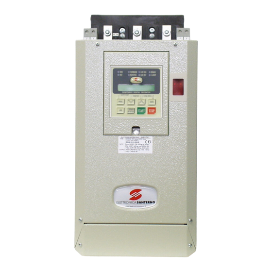
DCREG2
DCREG4
USER MANUAL
28/05/18 R.07
SOFTWARE VERSION D5.02
Elettronica Santerno S.p.A.
Via della Concia, 7 – 40023 Castel Guelfo (BO) Italy
Tel. +39 0542 489711 - Fax +39 0542 489722
santerno.com
• 15P0059B3 •
info@santerno.com
E n g l i s h
Advertisement
Table of Contents

Related Manuals for Santerno DCREG4 Series

Summarization of Contents
1 DELIVERY CHECK
1.1 NAMEPLATE
Details the identification plate on the converter's front side.
1.2 TRANSPORT AND HANDLING
Provides guidelines for safe and damage-free handling of the DCREG unit.
1.3 UNPACKING
Step-by-step instructions for unpacking the DCREG from its packaging.
2 START-UP
2.1 INTRODUCTION
Overview of checks and operations for optimal DCREG drive adjustment.
2.2 PRELIMINARY CHECKS
Essential checks before initial operation, including voltage and wiring.
2.3 SCHEDULED MAINTENANCE
Defines maintenance tasks and minimum intervals for the converter.
2.4 MAIN CHECKS AND CONFIGURATIONS
Guides through essential checks and initial configurations for the drive.
2.5 SPEED CONTROL MODE OPERATION
Details operation procedures for speed control with different feedback types.
2.6 RAMP CONFIGURATION IN SPEED CONTROL MODE
Explains programming of ramp times for acceleration and deceleration.
2.7 SPEED CONTROL OPTIONS
Describes options for adjusting analog inputs for speed control.
2.8 CURRENT (TORQUE) CONTROL MODE OPERATION
Explains operation in current or torque control mode for specific applications.
2.9 CURRENT LIMIT CONTROL OPTIONS
Details options for controlling and limiting the current in various modes.
2.10 ANALOG AND DIGITAL OUTPUTS
Describes configuration and functionality of analog and digital outputs.
2.11 BACKUP AND RESTORATION OF STORED PARAMETERS
Procedure for backing up and restoring drive parameters.
3 GENERAL CHARACTERISTICS
3.1 GENERAL DESCRIPTION
Provides a general overview of the DCREG series drives and their capabilities.
AUTOMATIC TUNING
Explains the drive's ability to automatically calculate motor and load parameters.
SERIAL INTERFACE
Details the serial communication options (MODBUS) for the drive.
FIELDBUS
Describes the availability and configuration of fieldbus communication.
ANALOG INPUTS
Details the specifications and configuration of analog inputs.
INTERNAL REFERENCES
Describes the preset run references and jog references available.
RAMP FUNCTION
Explains the digital ramp function for acceleration/deceleration.
ANALOG OUTPUTS
Describes the configuration and functionality of analog outputs.
DIGITAL INPUTS
Details the functionality of the configurable digital inputs.
DIGITAL OUTPUTS
Describes the functionality of the configurable digital outputs.
LOCAL MODE OPERATION
Explains how to operate the drive using the local keypad.
DRIVE ADJUSTMENTS
Covers storing parameters, restoring defaults, and firmware updates.
PROTECTIONS
Lists the drive's internal and external protection mechanisms.
STANDARDS
Details EMC and Low-Voltage Directive compliance.
WORKING TEMPERATURES
Specifies operating temperature ranges and derating information.
MAXIMUM OPERATING ALTITUDE
Specifies the maximum operating altitude and derating.
RELATIVE HUMIDITY
Specifies the acceptable relative humidity range.
WEIGHT
Provides the weight specifications for different drive sizes.
OVERLOAD CAPACITY
Details the drive's overload capabilities and duty cycle.
3.32 DCREG SIGNAL CONNECTIONS
3.33 SIGNAL TERMINALS
Details the function and I/O ratings of each signal terminal.
4 KEYPAD AND ALPHANUMERIC DISPLAY
4.1 KEYS OPERATING MODES
Describes the functions of the keys on the keypad.
4.2 FUNCTIONS DISPLAYED BY THE LEDS
Explains the meaning of the LEDs on the alphanumeric display.
4.3 LOCAL OPERATING MODE
Details how to switch and operate the drive in local mode.
4.4 REMOING THE KEYPAD
Instructions for safely removing and relocating the keypad.
5 FIRMWARE STRUCTURE
5.1 GENERAL
Overview of the drive's firmware and parameter storage.
5.2 BLOCK DIAGRAM
Illustrates the functional blocks of the drive's control system.
5.3 PARAMETER COPY
Explains the process of copying and managing drive parameters.
6 SPECIAL FEATURES
6.1 AUTOTUNING
Describes procedures for automatic tuning of motor and load parameters.
6.2 RAMPS OVER THE REFERENCE
Explains programming of ramp times for smooth reference changes.
6.3 MOTOR POTENTIOMETER
Details the function of the internal reference adjustment.
6.4 CURRENT LIMITATION
Explains parameter settings for controlling motor current limits.
6.5 OPERATION QUADRANTS
Defines the four operation quadrants based on speed and torque.
6.6 MOTOR HEATING THERMAL IMAGE
Describes how the drive monitors motor temperature rise.
6.7 FIELD REGULATOR
Explains the field current regulation and weakening modes.
6.8 CONFIGURABLE DIGITAL OUTPUTS
Details the configuration options for digital outputs.
6.9 ADAPTIVE SPEED PARAMETERS
Explains parameters for dynamically adjusting speed loop gains.
6.10 ELECTROMAGNETS APPLICATION
Covers power connections and protection for electromagnet loads.
6.10.2 DCREG4 ELECTROMECHANICAL DIAGRAM FOR REFERENCE SWITCHING
Electromechanical diagram for DCREG4 reference switching.
6.10.3 DCREG4 SETTING PARAMETER VALUES DIFFERENT FROM DEFAULT VALUES
Lists DCREG4 parameter values that differ from default settings.
6.10.4 DCREG4 OPERATION DESCRIPTION
Describes the operation sequence for DCREG4 with electromagnets.
6.10.5 DCREG2 ELECTROMECHANICAL DIAGRAM FOR REFERENCE SWITCHING
Electromechanical diagram for DCREG2 reference switching.
6.10.6 DCREG2 SETTING PARAMETER VALUES DIFFERENT FROM DEFAULT VALUES
Lists DCREG2 parameter values that differ from default settings.
6.10.7 DCREG2 OPERATION DESCRIPTION
Describes the operation sequence for DCREG2 with electromagnets.
6.10.8 ENERGIZING/DEENERGIZING CURRENT PATTERNS
Illustrates current patterns during electromagnet energizing/de-energizing.
6.10.9 OPERATION WITH BACK-UP BATTERIES
Details operation with backup batteries for electromagnets.
6.10.10 ALARMS
Explains alarm conditions and handling procedures.
7 OPERATION PARAMETERS
7.1 MEASURE PARAMETERS
Details parameters that display drive status and measured values.
7.2 PROGRAMMING PARAMETERS
Covers all parameters that can be programmed by the user.
7.3 CONFIGURATION PARAMETERS
Details parameters for configuring drive functions and settings.
8 DIAGNOSTICS
8.1 ALARM PARAMETERS
Lists and explains all possible alarm codes and their meanings.
8.2 WARNING PARAMETERS
Lists and explains all possible warning messages and their implications.
Need help?
Do you have a question about the DCREG4 Series and is the answer not in the manual?
Questions and answers