Table of Contents
Advertisement
Advertisement
Table of Contents

Related Manuals for ILX Lightwave LDX-36000 Series


Summary of Contents for ILX Lightwave LDX-36000 Series
- Page 1 User’s Guide LDX-36000 Series High Power Laser Diode Current Source ILX Lightwave Corporation · P. O. Box 6310 · Bozeman, MT, U.S.A. 59771 · U.S. & Canada: 1-800-459-9459 · International Inquiries: 406-556-2481 · Fax 406-586-9405 · ilx.custhelp.com www.ilxlightwave.com 70039705 March 2010...
-
Page 3: Table Of Contents
Optical Safety ..........18 03_10 LDX-36000 Series... - Page 4 Additional Functions and Features ....... . 41 LDX-36000 Series...
- Page 5 Query Response Timing ........63 03_10 LDX-36000 Series...
- Page 6 Appendix B Allowed QCW Space - LDX-36125-24 Allowed QCW Operating Region for 36125-24 ..... . . 142 LDX-36000 Series...
- Page 7 Figure 1.1 LDX-36000 Series Front Panel ..... 3 Figure 1.2 LDX-36000 Series Rear Panel, <50 A ....3 Figure 1.3 LDX-36000 Series Rear Panel, >50 A .
- Page 8 Figure 4.7 Laser Output Off Register ......62 Figure A.1 Allowed QCW Operating Region ....140 Figure B.1 Allowed QCW Operating Region for LDX-36125-24 . . . 142 LDX-36000 Series...
- Page 9 Table 1.1 Options and Accessories ......6 Table 1.2 LDX-36000 Series Specifications..... 7 Table 3.1 LDX-36000 Series Default Configuration .
- Page 10 L I S T O F TA B L E S viii LDX-36000 Series...
-
Page 11: Safety Information And The Manual
• Prolonged storage under adverse conditions • Failure to perform intended measurements or functions If necessary, return the instrument to ILX Lightwave, or the authorized local ILX Lightwave distributor, for service or repair to ensure that safety features are maintained (see the contact information on page xiv). - Page 12 • Maximum Relative Humidity: <80% RH, non-condensing • Operating temperature range of 0 °C to 40 °C • Storage and transportation temperature of –40 °C to 70 °C • Maximum altitude: 3000 m (9843 ft.) • This equipment is suitable for continuous operation. LDX-36000 Series...
-
Page 13: Safety Marking Symbols
Off: Out position of a bistable push control. The slash (I) only denotes that mains are on. The circle (O) only denotes that mains are off. Standby: This switch does not fully disconnect the instrument from the power supply. 03_10 LDX-36000 Series ... - Page 14 Returning an Instrument If an instrument is to be shipped to ILX Lightwave for repair or service, be sure to: Obtain a Return Authorization number (RA) from ILX Customer Service.
-
Page 15: Comments, Suggestions, And Problems
You must negotiate and settle with the carrier for the amount of damage. Comments, Suggestions, and Problems To ensure that you get the most out of your ILX Lightwave product, we ask that you direct any product operation or service related questions or comments to ILX Lightwave Customer Support. - Page 16 ILX Lightwave instrument: Description of the problem: If ILX Lightwave determines that a return to the factory is necessary, you are issued a Return Authorization (RA) number. Please mark this number on the outside of the shipping box.
-
Page 17: Introduction And Specifications
C H A P T E R NTRODUCTION AND PECIFICATIONS This chapter is an introduction to the LDX-36000 Series High Power Laser Diode Current Sources. The chapter contains first time setup information, important safety considerations, maintenance information, instrument specifications, and general LDX-36000 Series information. -
Page 18: Product Overview
Product Overview Product Overview The LDX-36000 Series High Power Laser Diode Current Sources are capable of delivering very high currents, up to 125A CW and 220A QCW with a compliance voltage up to 35 Volts. These current sources are designed for testing and... -
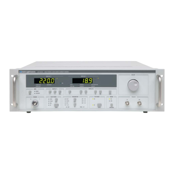
Page 19: Figure 1.1 Ldx-36000 Series Front Panel
I N T R O D U C T I O N A N D S P E C I F I C A T I O N S C H A P T E R Product Overview Figure 1.1 LDX-36000 Series Front Panel Figure 1.2 LDX-36000 Series Rear Panel, <50 A Figure 1.3 LDX-36000 Series Rear Panel, >50 A 03_10 LDX-36000 Series... -
Page 20: Installation
IEC safety standards. AC Power Requirements The LDX-36000 Series Current Sources may be operated from a single phase power source delivering nominal line voltages in the range of 100 to 240 VAC ±10% (all values RMS), from 50 to 60 Hz. Please refer to specifications for proper line voltage for your instrument. -
Page 21: Tilt-Foot Adjustment
Chapter 4 - Remote Operation. Tilt-Foot Adjustment The LDX-36000 Series Current Sources come standard with folding front legs and two rear feet to use as a benchtop instrument. Extending the front feet so the instrument front panel is tilted up makes it easier to view the displays. To use them, place the unit on a stable base and rotate the front legs downward until they lock into position. -
Page 22: Obtaining Repair Services
There are no user-serviceable parts inside the instrument, excepting any external fuses in the AC power entry module. Contact ILX Customer Service for information about servicing the instrument. Options and Accessories Options and accessories for the LDX-36000 series of instruments include the following: Table 1.1 Options and Accessories Description... -
Page 23: Specifications
I N T R O D U C T I O N A N D S P E C I F I C A T I O N S C H A P T E R Specifications Specifications Table 1.2 LDX-36000 Series Specifications (Sheet 1 of 8) 36010-12 36025-12 36050-12... - Page 24 I N T R O D U C T I O N A N D S P E C I F I C A T I O N S C H A P T E R Specifications Table 1.2 (Continued) (Sheet 2 of 8) LDX-36000 Series Specifications 36010-12 36025-12 36050-12 36085-12...
-
Page 25: Table 1.2 Ldx-36000 Series Specifications
I N T R O D U C T I O N A N D S P E C I F I C A T I O N S C H A P T E R Specifications Table 1.2 (Continued) (Sheet 3 of 8) LDX-36000 Series Specifications 36010-12 36025-12 36050-12 36085-12... - Page 26 I N T R O D U C T I O N A N D S P E C I F I C A T I O N S C H A P T E R Specifications Table 1.2 (Continued) (Sheet 4 of 8) LDX-36000 Series Specifications 36010-12 36025-12 36050-12 36085-12 36125-12 AC power failure / brown-out detection;...
- Page 27 I N T R O D U C T I O N A N D S P E C I F I C A T I O N S C H A P T E R Specifications Table 1.2 (Continued) (Sheet 5 of 8) LDX-36000 Series Specifications 36010-35 36018-35 36040-30 36070-30...
- Page 28 I N T R O D U C T I O N A N D S P E C I F I C A T I O N S C H A P T E R Specifications Table 1.2 (Continued) (Sheet 6 of 8) LDX-36000 Series Specifications 36010-35 36018-35 36040-30 36070-30...
- Page 29 I N T R O D U C T I O N A N D S P E C I F I C A T I O N S C H A P T E R Specifications Table 1.2 (Continued) (Sheet 7 of 8) LDX-36000 Series Specifications 36010-35 36018-35 36040-30 36070-30...
- Page 30 I N T R O D U C T I O N A N D S P E C I F I C A T I O N S C H A P T E R Specifications Table 1.2 (Continued) (Sheet 8 of 8) LDX-36000 Series Specifications 36010-35 36018-35 36040-30 36070-30 36125-24 Adjustable current and voltage limit;...
- Page 31 Hardware fault detection time due to an open circuit, intermittent contact, voltage or current limit, AC power failure. Pulse mode specifications are also external trigger mode specifications. In keeping with our commitment to continuous improvement, ILX Lightwave reserves the right to change specifications without notice for such changes.
- Page 32 I N T R O D U C T I O N A N D S P E C I F I C A T I O N S C H A P T E R Specifications LDX-36000 Series...
-
Page 33: Safety
In addition, improperly sized output cables and poor connections may get hot due to Joule heating. Continued operation may result in insulation meltdown and fire. If there is a question regarding a cable's current carrying capacity, call ILX Lightwave for resolution. -
Page 34: Laser Safety
Laser Safety WARNING While the LDX-36000 Series Current Source is not a complete laser system, the instruments are capable of driving high power, Class IV lasers. Because of this, extreme care must be exercised during operation. Only personnel familiar with the operation of high power lasers should operate these instruments. - Page 35 10 Advise all those that may work around the laser of these precautions. It is recommended that the laser be operated in a room with controlled and restricted access. Any available interlocks on the laser system should be connected to doors that enter the restricted area. 03_10 LDX-36000 Series ...
-
Page 36: Safety Features And Compliance To Government Regulations
Safety Features and Compliance to Government Regulations The LDX-36000 series laser diode controllers are designed to meet CE safety standards as detailed in the specifications. If part of a complete laser system, it is compliant with CDRH and CE laser safety standards. -
Page 37: Operating Controls (As Appropriate)
Refer to Figure 2.1 for the location of all safety labels on the instrument. Earth Ground CAUTION: Refer to Manual CAUTION: Risk of Electric Shock CE Mark Figure 2.1 LDX-36000 Series Rear Panel Labels, <50 A 03_10 LDX-36000 Series ... -
Page 38: Figure 2.2 Ldx-36000 Series Rear Panel Labels, >50 A
S A F E T Y C H A P T E R Safety Features and Compliance to Government Regulations Earth Ground Caution, refer to manual CE Mark Figure 2.2 LDX-36000 Series Rear Panel Labels, >50 A LDX-36000 Series... -
Page 39: Operation
PERATION This chapter is an introduction to the operation of the LDX-36000 Series High Power Current Sources. It offers instructions for connecting a high power laser to the current source and describes powering up the instrument. This chapter also contains step by step procedures on how to operate the current source in CW and QCW modes. -
Page 40: Power-On State
Current Setpoint = 0.0 A Connections for General Operation When connecting a laser diode to the LDX-36000 Series current source, it is recommended that the instrument be powered up and the output disabled. In this condition, a low impedance shunt is active across the output terminals. When disconnecting devices, it is only necessary to disable the output. -
Page 41: Inductance
The output terminals are left floating relative to earth ground to suppress AC power-on/power-off transients that may occur through an earth-ground path as well as accommodate different laser packages and grounding schemes. If the 03_10 LDX-36000 Series ... -
Page 42: Laser Current Source Output
Figure 3.1 Laser and Photodiode Connections Laser Current Source Output For the LDX-36000 Series models, the current source output connector is either a combination D 9W4 connector on models with less than 50A output (CW), Figure 3.2, or high current terminals on models with more than 50A output (CW), Figure 3.3. -
Page 43: Figure 3.2 Ldx-36000 Output And Measurement Connector Pin
O P E R A T I O N C H A P T E R Connections for General Operation Figure 3.2 LDX-36000 Output and Measurement Connector Pin Assignments, <50A Figure 3.3 LDX-36000 Output and Measurement Connector Pin Assignments, >50A 03_10 LDX-36000 Series ... -
Page 44: External Interlocks
These lines are available on the back panel connector labeled Sense. Refer to Figure 3.2 the pinout. Note: A cable separate from the output cable is required for voltage measurements. LDX-36000 Series... -
Page 45: External Photodiode Measurement
Note: The instrument measures forward voltage, photodiode current and temperature in CW and QCW modes. In QCW mode, measurement accuracy is achieved by measuring in the last 15 s of the pulse and throughout the pulse at pulse widths > 1ms. 03_10 LDX-36000 Series ... -
Page 46: Front Panel Operation
Front Panel Operation Front Panel Operation This section describes the fundamentals of operation for the LDX-36000 Series High Power Laser Current Source. The order of descriptions will follow the normal progression of how one would typically configure the instrument for use for the first time. -
Page 47: Display 2
(Const %, Const Freq) and error indicators. If any error has been detected, the output will be disabled. This behavior may be changed via the Output Off Register (described in detail in Chapter 4). 03_10 LDX-36000 Series ... -
Page 48: Temperature Measurement Setup
Output Off Register or setting thermistor calibration constants to zero. Temperature Measurement Setup The LDX-36000 Series High Power Laser Current Sources are designed to measure temperature of a laser diode mount and disable the output if temperature exceeds a specified value. Temperature measurement is accomplished by measuring the resistance of a negative temperature coefficient (NTC) thermistor. -
Page 49: Table 3.3 Typical 10 Kw @ 25°C Thermistor Calibration Values
In order to use the temperature measurement feature of the LDX-36000, nonzero values for the Steinhart-Hart constants must be entered. Using an uncalibrated ILX Lightwave 10 k @ 25°C thermistor, the typical values shown in Table 3.3 may be entered to give a measurement accuracy of approximately ±2°C. If higher accuracy is required, a calibrated thermistor must be used. -
Page 50: Limit Setup
Parameter Select button, the display reverts to normal operation. Pressing the Parameter Select button while in normal operational mode will illuminate the parameter that was highlighted the last time the parameters were adjusted, even after power cycling. LDX-36000 Series... -
Page 51: Configuring The Operational Mode
C H A P T E R Front Panel Operation Configuring the Operational Mode The LDX-36000 Series has two main operational modes - CW (continuous wave) and QCW (quasi-continuous wave or pulsed). The currently selected operating mode may be identified in two ways. Either the CW or QCW... -
Page 52: Qcw (Pulsed) Mode Setup
CW to QCW mode. Once the QCW operational mode has been enabled, the last enabled QCW mode LED will be illuminated. There are two current ramp features built into the LDX-36000 Series drivers when pulsing high power laser diodes in either QCW mode or HPulse mode. When the output is first enabled with the “OUTPUT”... -
Page 53: Figure 3.11 Qcw Current Ramp Enabling Output
The step size and ramp time is a function of the full-scale output current, duty cycle and range of the set-point step and is controlled by the instrument and cannot be adjusted through the instrument's front panel or GPIB commands. Figure 3.12 QCW Current Ramp with Output Enabled 03_10 LDX-36000 Series ... -
Page 54: Qcw-Pulse Mode
Pressing the % button displays the current duty cycle setpoint as a percentage on Display 2. The Const % LED is illuminated. If the Adjust button is pressed and the Adjust knob rotated within three seconds, the duty cycle may be changed. LDX-36000 Series... -
Page 55: Qcw-Trig Mode
Pressing the % or Freq button will result in dashes "- - -" being shown in Display 2. If the frequency of the external trigger exceeds 1 kHz, the instrument will ignore the next rising edge. The output pulse will be limited to 1 kHz. 03_10 LDX-36000 Series ... -
Page 56: Hard Pulse Mode
Note: The EXT PULSE OUT output is designed to drive 50 . Any measurement equipment connected to this output should be configured for 50 impedance as well. Otherwise, the output signal may induce extraneous noise in the measurement. LDX-36000 Series... -
Page 57: Automatic Shutoff Conditions For Current Output
• High impedance error • High load inductance • Failed power supply Additional Functions and Features This section describes special functions and features of the LDX-36000 Series High Power Current Source. Adjusting Current Setpoint in Terms of Optical Power Pressing the P/P button until the annunciator W is illuminated allows the laser drive current to be set in terms of optical power. -
Page 58: Figure 3.15 Determining Output Current Setpoint
Once the laser current setpoint has exceeded threshold, Display 1 will indicate calculated optical power. If the threshold (P2) is set to 0.0, the power mode is considered to be uncalibrated and Display 1 will show "- - - -" when power mode is selected. LDX-36000 Series... -
Page 59: Configuring External Photodiode Power Measurements
Display 1 in Volts. Next, press the Parameter Set button and rotate the Adjust knob to change the bias level. LIV Sweep Mode An automated L-I-V mode is available on some LDX-36000 Series instruments and is accessible through GPIB commands only. LDX-36010-12... -
Page 60: Table 3.5 Automated L-I-V Mode Gpib Commands
Returns the LIV data from memory, in a group of 25 LASer:LIV:GETMEAS? data points. For each step, photodiode current, laser current setpoint, and laser forward voltage values are saved to memory. Specifies the start current, stop current, step current, LAS:LIV:SET and delay time between steps. LDX-36000 Series... -
Page 61: Pulse Out
Trigger In The LDX-36000 Series instruments accept a TTL level input signal to initiate an output current pulse. The TRIGGER IN BNC connector is located to the right of center on the front panel. The leading edge of this signal is used to initiate an output pulse;... -
Page 62: Saving And Recalling From The Front Panel
Saving and Recalling from the Front Panel For applications where several different instrument configurations may be required for different types of testing, the LDX-36000 Series High Power Current Sources offer a useful Save and Recall feature. The SAVE feature allows all front panel settings for a given instrument configuration to be easily stored for future use. -
Page 63: Remote Operation
"device dependent message" or a "device dependent command". Interface messages manage the bus, with functions such as initializing the bus and addressing or unaddressing devices. In addition, some individual bus lines are designated for this purpose. LDX-36000 Series ... -
Page 64: Talkers, Listeners, And Controllers
Figure 4.1 GPIB Cable Connections The GPIB Connector The standard GPIB connector consists of 16 signal lines in a 24-pin stackable connector. The extra pins are used to make twisted pairs with several of the lines. LDX-36000 Series... -
Page 65: Figure 4.2 Gpib Connector Diagram
• SRQ (service request) can be set by any device in the system to request service from the controller. • EOI (end or identify) is used by talkers to identify the end of a message. Figure 4.2 GPIB Connector Diagram 03_10 LDX-36000 Series ... -
Page 66: Reading The Gpib Address
1 Hz to indicate the complete disabling of the front panel. The Talk/Listen LED will flash when communications are occurring over the GPIB bus. For more information on low level interface commands such as LLO, refer to the IEEE488.1 specification. LDX-36000 Series... -
Page 67: Command Syntax
To enhance readability, one or more white spaces may be used before a comma, semicolon, or terminator. Since the computer normally places the terminator at the end of each command string (line), this simply means that an extra space character at the end of the command line works acceptably. 03_10 LDX-36000 Series ... -
Page 68: Terminators
Some commands require a parameter. The parameter must be separated by at least one white space. The syntax symbol <nrf value> refers to the flexible numeric representation defined by the GPIB standard. It means that numbers may be represented in LDX-36000 Series... -
Page 69: Table 4.4 Parameters
LAS:CALT 1.111, 2.004, 0.456 All parameters of a multi-parameter command must be entered, even if only some of them need to be changed. For example: LAS:CALT 1.111, 0.456 will generate an error. The second parameter must be included. 03_10 LDX-36000 Series ... -
Page 70: Command Tree Structure
LAS:LDI? Command Tree Structure The LDX-36000 Series current source device-dependent commands are structured in a tree format as shown in Figure 4.4. Each of the legal paths is shown, followed by its list of path options, followed by the commands themselves. -
Page 71: Syntax Summary
Missing colon; MODE? expected LAS:OUT ON INC Missing semicolon; INC command generates an error LAS:DIS ? Space not allowed before question mark; DIS command expected Las:LDI5.4;dis? Space missing between LDI command and the parameter value 5.4 03_10 LDX-36000 Series ... -
Page 72: Ieee-488.2 Command Commands
Numeric data is required with *PSC (1 = on, 0 = off), *RCL (0-10, see front panel Recall funcation), *SAV (1-10, see front panel Save function), *ESE (0-255, see Figure 4.2 - GPIB Connector diagram), and *PUD (for factory use only). LDX-36000 Series... -
Page 73: Table 4.7 Ldx-36000 Ieee Common Commands
*ESE *ESE? *ESR? *IDN *OPC *OPC? *PSC *PSC? *PUD *PUD? *RCL *RST *SAV *SRE *SRE? *STB *TST? *WAI See Chapter 5 - Command Reference for descriptions of all commands, including common commands, supported by the LDX-36000. 03_10 LDX-36000 Series ... -
Page 74: Ldx-36000 Commonly Used Commands
LAS:LIM:V NONE Returns the current output mode of the instrument LAS:MODE? NONE Sets the output mode to CW LAS:MODE:CW NONE Sets the output mode to hard pulse mode LAS:MODE:HPULSE NONE Sets the output mode to pulsed LAS:MODE:PULSE LDX-36000 Series... - Page 75 Returns current pulsewidth value LAS:PW? Sets pulsewidth while holding frequency constant; duty LAS:PWF cycle percentage will change Sets pulsewidth while holding duty cycle percentage LAS:PWP constant; frequency will change NONE Returns thermistor resistance measurement NONE Returns current temperature measurement 03_10 LDX-36000 Series ...
-
Page 76: Status Reporting
Querying a Condition Register does not change its contents. Figure 4.6 shows the status reporting scheme of the LDX-36000 Series Current Source. Each of the registers which may be accessed by a command or query has the appropriate command or query written above or below the register representation. -
Page 77: Operation Complete Definition
Note: If the GPIB times out while waiting for a response, either set the GPIB time-out longer or use SRQ-generated interrupts. See the GPIB interface manual for time-out configuration or SRQ programming setup. The *OPC, *OPC?, and *WAI commands should not be used inside a calibration routine. 03_10 LDX-36000 Series ... -
Page 78: Output Off Register
09 - Disabled 02 - Enabled 10 - *Enabled 03 - *Enabled 11 - *Enabled 04 - *Enabled 12 - *Enabled 05 - *Enabled 13 - *Enabled 06 - Disabled 14 - *Enabled 07 - Disabled 15 - *Enabled LDX-36000 Series... -
Page 79: Command Timing
Query responses are evaluated at the time the query request is parsed, and not at the time the response message is sent. In most cases, this does not create a problem since the time between parsing a query and sending its response is small. 03_10 LDX-36000 Series ... - Page 80 R E M O T E O P E R A T I O N C H A P T E R Command Timing LDX-36000 Series...
-
Page 81: Command Reference
This chapter is a guide to all of the device-dependent commands for the LDX-36000 Series High Power Laser Current Source. This chapter is divided into two parts. The first part contains an overview of the remote commands used by the LDX-36000 current source. -
Page 82: Remote Command Reference Summary
Remote Command Reference Summary Remote Command Reference Summary This section contains all of the commands for the LDX-36000 Series High Power Current Source, listed in alphabetical order. Subsections for each path are presented, listing the commands which are legal for that path. See Figure 4.4 for the command path tree structure. - Page 83 Turns on Display 1 to show laser output current. LAS:DIS:LDI NONE Returns on/off status of the laser output current display. LAS:DIS:LDI? NONE Turns onDisplay 1 to show laser voltage. LAS:DIS:LDV NONE Returns on/off status of the laser voltage display. LAS:DIS:LDV? 03_10 LDX-36000 Series ...
- Page 84 Returns the laser current source setpoint value. LAS:LDI? NONE Returns the measured laser voltage value. LAS:LDV? Sets the laser current source limit. LAS:LIM:I NONE Returns the laser current source limit. LAS:LIM:I? Sets the laser high temperature limit. LAS:LIM:T LDX-36000 Series...
- Page 85 Specifies the pulsewidth to be output QCW mode. Duty LAS:PWF cycle will change to maintain constant frequency. Specifies the pulsewidth to be output QCW mode. LAS:PWP Frequency will change to maintain constant duty cycle. Sets laser current setpoint step value. LAS:STEP 03_10 LDX-36000 Series ...
- Page 86 NONE Returns the elapsed time since the instrument was last TIMER? reset. NONE Initiates an internal self-test and returns a response when *TST? complete. NONE Prevents executing any further commands until the *WAI No-Operation-Pending flag is true. LDX-36000 Series...
-
Page 87: Command Reference
Command Reference Command Reference The following pages contain a reference for both common and devide-dependent commands of the LDX-36000 Series High Power Laser Diode Current Source. This reference contains useful information for both local and remote operation of the LDX-36000. - Page 88 "ERR?" -response: 0, meaning no errors have been reported. "Errors?" -response: 501,509, meaning the output was disabled due to an interlock being opened and a high temperature limit being reached at some point since the last query. LDX-36000 Series...
- Page 89 Enable Register *ESE <nrf> *ESE? Examples "*ESE 40" -action: Sets the Standard Event Status Enable Register to enable Bit 5 of the Status Byte Register if a device-dependent error or a command error occurs (40 = 2 03_10 LDX-36000 Series ...
- Page 90 4 – Execution Error & & 5 – Command Error & & 6 – User Request 7 – Power On Standard Event Status Enable Register *ESE <nrf> *ESE? Examples "*ESR?" -response: 32, meaning a command error has occurred. LDX-36000 Series...
- Page 91 Returns a comma delimited standard format ASCII identification string, from information stored in the instrument during manufacture. The information will contain at a minimum the instrument's model number and serial number. Examples "*IDN?" -response: ILX Lightwave,3650,36501234YN,1.2 LASer:CAL:LDI <nrf value>,<nrf value> OMMON RONT...
- Page 92 "las:cal:limiti 1.0046, -0.00426" -action: Adjusts the internal calibration to linearize the current limit setpoint by entering a new slope and offset of 1.0046 and -0.00426, respectively. "Las:Cal:LIMITI 1.0, 0.0" -action: Resets the laser current limit setpoint calibration constants to default values. LDX-36000 Series...
- Page 93 This procedure is outlined in Chapter 6. Examples "las:cal:limitv?" -response: 1.545116, 0.379247, meaning a slope of 1.545116 and an offset of 0.379247 had been previously entered as part of the calibration process. 03_10 LDX-36000 Series ...
- Page 94 "las:cal:thermi 1.004874, 0.049776" -action: Adjusts the internal D/A calibration to adjust the thermistor current by entering a new slope and offset of 1.004874 and 0.049776, respectively. "Las:Cal:ThermI 1.0, 0.0" -action: Resets the photocurrent measurement calibration constants to default values. LDX-36000 Series...
- Page 95 This procedure is outlined in Chapter 6. Examples "las:cal:thermv?" -response: 1.566841, 0.089274, meaning a slope of 1.566841 and an offset of 0.089274 had been previously entered as part of the calibration process. 03_10 LDX-36000 Series ...
- Page 96 LO-xx where xx is percentage below threshold. Examples "las:calp?" -response: 1.56, 3.2; meaning a value of 1.56 W/A has been entered for the laser slope efficiency and the laser has a threshold of 3.2 A. LDX-36000 Series...
- Page 97 Amps, otherwise, it will display calculated optical power from measured photocurrent. Examples "LAS:CALPD?" -response: 1.43; meaning that the value of 1.43 mA / W was entered as the responsivity value for an external photodiode connected to the instrument for power monitoring. 03_10 LDX-36000 Series ...
- Page 98 When all three constants are zero, the temperature display is disabled and the open sensor and temperature limit error LEDs are disabled and will not disable the output. Typical values to use for an ILX Lightwave uncalibrated 10 k thermistor are: C1 = 1.125 (x10 C2 = 2.347 (x10 C3 = 0.855 (x10...
- Page 99 *CLS command is issued. Examples "LAS:COND?" -response: 257, means that the output is on and in current limit. "Radix Hex; Laser:Cond?" -response: #H90, means that the temperature sensor is shorted and Interlock 1 is open. 03_10 LDX-36000 Series ...
- Page 100 Notes The value returned is a percentage. The range for duty cycle value depends on instrument mode (pulse or hard pulse mode) and model. Examples "LAS:DC?" -response: "5.2", means the QCW duty cycle is set to 5.2%. LDX-36000 Series...
- Page 101 5 100mW steps with an approximate 1.5 second delay between each step. The actual current setpoint is varied by back-calculating from the optical power by using the threshold and slope efficiency values entered via the LAS:CALP command. 03_10 LDX-36000 Series ...
- Page 102 Returns the delay, in seconds, between an input trigger pulse and the rising edge of the output current pulse. Parameters None. Notes The default value is 0 seconds. Examples "LAS:DELAYIN?" -response: "2.5e-3", means the delay between an input trigger and output current pulse will be 2.5 ms. LDX-36000 Series...
- Page 103 Action Returns the delay, in seconds, between an output QCW pulse and the output trigger. Parameters None. Examples "LAS:DELAYOUT?" -response: "2.5e-3", means the delay between an output current pulse and the trigger output is 2.5 ms. 03_10 LDX-36000 Series ...
- Page 104 Sets Display 2 to show the QCW-Pulse mode pulse frequency. Parameters None. Notes The frequency display is automatically turned off when another display selection is enabled. Function is disabled unless in QCW-Pulse mode. Examples "LAS:DIS:F" -action: enables the frequency display on Display 2. LDX-36000 Series...
- Page 105 "LAS:DIS:LDI?" -response: 0, means that the output current button I is not currently active, current setpoint is not being shown on Display 1. "LAS:DIS:LDI?" -response: 1, means that the output current button I is currently active, current setpoint is shown on Display 1. 03_10 LDX-36000 Series ...
- Page 106 Through the use of previously determined laser threshold and slope efficiency values, the display indicates calculated optical power based on the current output current setpoint. Examples "LAS:DIS:P" -action: enables the output power display on Display 1. LDX-36000 Series...
- Page 107 Display 1. “LAS:DIS”:PPD?” -response: 1, means that the photodiode power measurement display is currently active; measured optical power or photocurrent is shown on Display 1. 03_10 LDX-36000 Series ...
- Page 108 Display will show pulsewidth setpoint in milliseconds. Display is disabled when instrument is in CW mode. The output power display is automatically turned off when another display selection is enabled. Examples “LAS:DIS:PWP” -action: enables the constant duty cycle pulsewidth setpoint display on Display 2. LDX-36000 Series...
- Page 109 Display 2 (°C will be illuminated when the display is in T mode). Examples "LAS:DIS:T?" -response: 0, means that the temperature measurement display is not currently active. "las:dis:t?" -response: 1, means that the temperature measurement display is currently active. 03_10 LDX-36000 Series ...
- Page 110 Status Byte. "Laser:Enable:Cond #HFFFF" -action: enables the Status Condition Register so that any and all of the above conditions will be reported in the Status Byte Register. LDX-36000 Series...
- Page 111 "LAS:ENAB:COND?" -response: 260, means the high temperature limit and output on conditions will be reported to the Status Byte (Bit 3). "Radix Hex; Laser:Enable:Cond?" -response: "#HFFFF" means that any and all of the above conditions will be reported to Bit 3 of the Status Byte. 03_10 LDX-36000 Series ...
- Page 112 "LAS:ENAB:EVENT 3" -action: enables the Status Condition Register so that the current and voltage limit conditions will be summarized in the Status Byte. "Laser:Enable:Cond #H0100" -action: enables the status condition register so that when the output is on , it will be reported in the Status Byte Register. LDX-36000 Series...
- Page 113 "LAS:ENAB:EVENT?" -response: "258", means a laser voltage limit or output status change will be reported (in summarized form) to the Status Byte Register (Bit 2). "Rad Hex; Laser:Enable:Eve?" -response: "#H30", means that an interlock opening or closing will be reported to the Status Byte Register. 03_10 LDX-36000 Series ...
- Page 114 "LAS:ENAB:OUTOFF 1791" -action: enables the Output Off Register so the laser output will be disabled if any of the conditions listed above occur. “las:enab:outoff 0” -action: disables all output off conditions except those that are permanently enabled. LDX-36000 Series...
- Page 115 ) are permanently disabled and cannot be changed. Examples "LAS:ENAB:OUTOFF?" -response: "1086" means, that either the laser voltage limit, high temperature limit, laser open circuit, the opening of interlocks #1 or #2, or the hardware current limit will force the laser output off. 03_10 LDX-36000 Series ...
- Page 116 The event status is only cleared when the event status is read or by the *CLS command, while the condition status (LAS:COND?) is constantly changing. Examples "LAS:EVE?" -response: "257" means, that the output status has changed and current limit events have occurred since the last LASer:EVEnt? query. LDX-36000 Series...
- Page 117 The frequency may be read from any operational mode but is only applicable to output while in the QCW-Pulse or Hard Pulse mode. Examples "LAS:F?" -response: 260, means that the QCW-Pulse or Hard Pulse frequency is set to 260 Hz. 03_10 LDX-36000 Series ...
- Page 118 LAS:CALPD command. Examples “LAS:IPD?” -response: “2543”, means the LDX-36000 is measuring 2.5423 mA from an external photodiode. “las:ipd?” -response: “14”, means the LDX-36000 is measuring 14 µA from an external photodiode. LDX-36000 Series...
- Page 119 Returns the output current setpoint. Parameters None. Notes The LAS:LDI? query does not return a measurement as is done with other ILX Lightwave instruments. It returns a value of the setpoint only. Examples "LAS:LDI?" -response: "4.5", means the output current setpoint is 4.5 A.
- Page 120 Returns the high temperature limit in °C. Parameters None. Notes The temperature limit may be queried even if temperature measurement has been disabled. Examples "las:lim:t?" -response: "25.7", means the high temperature limit has been set to 25.7°C. LDX-36000 Series...
- Page 121 "LAS:LIV:GETMEAS?” - response: “3, 5.00, 1.51, 120, 10.00, 1.81, 144,15.00,2.14,172,20.00,2.31,207,25.00,2.48” means data from a five point LIV run with pd current (A), laser current setpoint (A), and laser forward voltage (V) data for each laser setpoint value from 5.00 amps to 25.00 amps. 03_10 LDX-36000 Series ...
- Page 122 0.01A, and the number of LIV points is not more than 1000. Examples "LAS:LIV:SET?” - response “3.0, 12.0, 0.5, 0.02” means the start current is 3.0A, the stop current is 12.0A, the step current is 0.5A, and the delay time is 20 ms. LDX-36000 Series...
- Page 123 "las:liv:output 0” - action: LIV output is disabled. LASer:LIV:OUTPUT? OMMON RONT ANEL EVICE EPENDENT Action Returns status of LIV output. Parameters None. Notes None. Examples "LAS:LIV:OUT?” - response: 0 meaning the LIV output has been disabled. 03_10 LDX-36000 Series ...
- Page 124 In this mode, pulse width, frequency, and duty cycle are controlled either from the front panel or via GPIB. Examples “LAS:MODE:HPULSE” - action: output is diabled if it was on and the output mode is changed to hard pulse mode when the instrument is in QCW mode. LDX-36000 Series...
- Page 125 When the output is disabled, an internal short is placed across the output terminals. Examples "LAS:LDI 7.5; LAS:OUT ON" -action: output current setpoint is set to 7.5 amps and the output is enabled. "las:out 0" -action: output current is disabled and output shorting relay is closed. 03_10 LDX-36000 Series ...
- Page 126 The specified output power is NOT a setpoint for constant power mode as is the case for other ILX Lightwave instrumentation. Through the use of previously entered threshold and slope efficiency values via the LAS:CALP command, the optical power specified with the LAS:P command is used to calculate the laser current required to generate the specified output power.
- Page 127 The specified output power is NOT a setpoint for constant power mode as is the case for other ILX Lightwave instrumentation. It is a constant current mode whose output is back- calculated from a specified output optical power and a laser threshold and slope efficiency.
- Page 128 Examples "LAS:MODE:PULSE; LAS:F 100; LAS:PWF 95e-3; LAS:DC?" -action: places instrument in QCW-Pulse mode with a frequency of 100 Hz and a pulsewidth of 950 s. Duty cycle query returns a value of 9.5%. LDX-36000 Series...
- Page 129 0.1 corresponds to a power step of 100 mW. Examples "LAS:STEP?" -response: "0.1" means the step size is either 100 mA or 100 mW, depending on the mode. 03_10 LDX-36000 Series ...
- Page 130 ANEL -Operation Complete EVICE EPENDENT Action Sets the Operation Complete Bit in the Event Status Register when all pending overlapped commands have been completed. Parameters None. Notes See the IEEE 488.2 specification for additional information. Examples *OPC LDX-36000 Series...
- Page 131 1 - The enable registers are cleared during power on. Registers affected: Condition Status Enable Service Request Enable Event Status Enable Standard Event Status Enable See Chapter Four for more information on register structure. Examples *PSC? Request state of power-on status clear flag. 03_10 LDX-36000 Series ...
- Page 132 Returns the measured thermistor resistance in ohms. Parameters None. Notes This command is used to verify the accuracy of the thermistor calibration; see Chapter 6 for more information. Examples "R?" -response: "11215.547" means the thermistor resistance is 11215.547 ohms. LDX-36000 Series...
- Page 133 Returns the currently selected radix type. Parameters None. Notes DECimal is the default type at power-on. Examples "RAD?" -response: "Dec", the selected radix is decimal. "rad?" -response: "Hex", the selected radix is hexadecimal. "RADix?" -response: "Bin", the selected radix is binary. 03_10 LDX-36000 Series ...
- Page 134 It is normally not necessary to save the current setup for next power-on. The current setup is automatically stored for recall at next power-on, unless the *PSC command is used to clear the power-on status. Examples "*SAV 3" -response: the current instrument configuration is stored in memory location LDX-36000 Series...
- Page 135 Refer to Figure 4.6 in Chapter 4 for a complete description of the Status Byte and Service Request Enable Register. Examples "*STB?" -response: "200" specifies that the laser condition summary, master status summary and error available bits are enabled. 03_10 LDX-36000 Series ...
- Page 136 TERM 0 command is sent, or the instrument is turned off. Examples "Term?" -response: "1", the output terminator has been temporarily set to <CR><NL><^END>. "Term?" -response: "0", the output terminator is the IEEE-488.2 standard <NL><^END>. LDX-36000 Series...
- Page 137 20 more commands before the wait period is over. If more than 20 commands are sent before the delay or wait period is over, the additional commands will be ignored and an error E-220 will be generated. Examples "*WAI" -action: wait until OPC status is true. 03_10 LDX-36000 Series ...
- Page 138 C O M M A N D R E F E R E N C E C H A P T E R Command Reference LDX-36000 Series...
- Page 139 This chapter provides a troubleshooting guide in the event problems or errors are encountered while operating the LDX-36000. If this guide does not provide enough information to solve the problem, contact ILX Lightwave Customer Service for additional help. LDX-36000 Series...
-
Page 140: Calibration Overview
0-40°C. Finally, the LDX-36000 Series High Power Laser Current Source should be allowed to warm up, with the output on, a minimum of one hour prior to calibration. -
Page 141: Beginning Calibration
The default GPIB address for the 36000 is 1. This can be changed on the front panel of the 36000. All calibrations require slope and offset values to be sent to the 36000. Be sure to reset the calibration to default values (1,0) before each calibration is performed. 03_10 LDX-36000 Series ... -
Page 142: Laser Diode Current Setpoint Calibration
LAS:LDI setpoint - where "setpoint" is the current value in amps 13 Record the value of current measured by the current transducer. 14 Verify that the current setpoint is within the accuracy specifications of the instrument. LDX-36000 Series... -
Page 143: Qcw Calibration
LAS:LDI setpoint - where "setpoint" is the current value in amps 16 Record the value of current measured by the current transducer. 17 Verify that the current setpoint is within the accuracy specifications of the instrument. 03_10 LDX-36000 Series ... -
Page 144: Laser Diode Voltage Measurement Calibration
13 Set the voltage on the voltage source to 50% of the full scale voltage measurement. 14 Measure and record the voltage with the 36000 by sending the following command: LAS:LDV? 15 Verify that the voltage measurement is within the accuracy specifications of the instrument. LDX-36000 Series... -
Page 145: Voltage Limit Setpoint
13 Set the 36000 voltage limit to 50% of full scale. 14 Slowly increase the voltage on the adjustable voltage source until the voltage limit light is triggered. 15 Verify that the voltage limit is triggered within the accuracy specifications of the instrument. 03_10 LDX-36000 Series ... -
Page 146: Photodiode Current (Pdi) Measurement
11 Set the current on the current source to 50% of full scale ( 5 mA) 12 Retrieve the 36000’s photodiode current measurement with the following command: LAS:PPD? 13 Verify that the photodiode current measurement is within the accuracy specifications of the instrument LDX-36000 Series... -
Page 147: Thermistor Calibration
10K resistor. 13 Retrieve the 36000 measurement of the 10K resistance value with the following command: Resistance? 14 Verify that the measurement of the 10K resistor is within the accuracy specifications of the instrument. 03_10 LDX-36000 Series ... - Page 148 C A L I B R A T I O N A N D T R O U B L E S H O O T I N G C H A P T E R Thermistor Calibration If you wish to have ILX Lightwave calibrate your LDX-36000 unit, contact customer service at: 1-406-586-1244 or 1-800-459-9459 or sales@ilxlightwave.com.
-
Page 149: Troubleshooting
C H A P T E R Troubleshooting Troubleshooting This section is a guide to troubleshooting the LDX-36000 Series High Power Current Sources. Some of the more common symptoms are listed here, and the appropriate troubleshooting actions are given. It is recommended that troubleshooting begin at the top of the list and work toward the bottom. - Page 150 C H A P T E R Troubleshooting Open Circuit error E503 or Voltage The LDX-36000 series has an adjustable compliance voltage. Check to see if the voltage limit setting is too low. Limit error E505 prevents output from Check laser connections reaching desired value.
-
Page 151: Error Messages
E-100 to E-199 Parser Errors E-200 to E-299 Execution Control Errors E-300 to E-399 GPIB Errors E-400 to E-499 Not Applicable E-500 to E-599 Output Control Errors Note: Error codes not listed are reserved for future design use. 03_10 LDX-36000 Series ... -
Page 152: Table 6.3 Error Messages
Laser output disabled because of High Temperature Limit condition. E-511 Laser control (unknown) error disabled output. E-525 Open temperature sensor error. E-526 Shorted temperature sensor error. E-527 Power supply failure. E-528 Power supply voltage limit. E550 Pass element power limit E-599 Laser open circuit 2. LDX-36000 Series... -
Page 153: Error
E-599 Error No current measured by the instrument’s internal measurement circuits indicates an open circuit. This condition can be caused by an intermittent contact or fully open circuit. 03_10 LDX-36000 Series ... - Page 154 C A L I B R A T I O N A N D T R O U B L E S H O O T I N G C H A P T E R Error Messages LDX-36000 Series...
- Page 155 This Appendix illustrates the relationships of pulse frequency versus duty cycle for several different pulsewidth values. This information should be used as a guide to the user so they may properly configure their required QCW parameters. LDX-36000 Series ...
-
Page 156: Allowed Qcw Operating Region
A L L O W E D Q C W S P A C E Allowed QCW Operating Region Allowed QCW Operating Region Figure A.1 Allowed QCW Operating Region LDX-3600 Series... - Page 157 This Appendix illustrates the relationships of pulse frequency versus duty cycle for several different pulsewidth values. This information should be used as a guide to the user so they may properly configure their required QCW parameters. LDX-36000 Series ...
-
Page 158: Allowed Qcw Operating Region For 36125-24
A L L O W E D Q C W S P A C E - L D X - 3 6 1 2 5 - 2 4 Allowed QCW Operating Region for 36125-24 Allowed QCW Operating Region for 36125-24 Figure B.1 Allowed QCW Operating Region for LDX-36125-24 ...
Need help?
Do you have a question about the LDX-36000 Series and is the answer not in the manual?
Questions and answers