Table of Contents
Advertisement
Quick Links
Advertisement
Table of Contents

Related Manuals for ILX Lightwave LDX-3620


Summary of Contents for ILX Lightwave LDX-3620
- Page 1 User’s Guide Ultra Low Noise Current Source LDX-3620 ILX Lightwave Corporation P. O. Box 6310 Bozeman, MT, U.S.A. 59771 · · · U.S. & Canada 1-800-459-9459 · International Inquiries: 406-586-1244 Fax 406-586-9405 · E-mail: support@ilxlightwave.com www.ilxlightwave.com 70001802_7/01...
- Page 3 • Prolonged storage under adverse conditions • Failure to perform intended measurements or functions If necessary, return the instrument to ILX Lightwave, or authorized local ILX Lightwave distributor, for service or repair to ensure that safety features are maintained. All instruments returned to ILX Lightwave are required to have a Return Authorization Number assigned by an official representative of ILX Lightwave Corporation.
- Page 4 Technical specifications including electrical ratings and weight are included within the manual. See the Table of Contents to locate the specifications and other product information. The following classifications are standard across all ILX Lightwave products: • Indoor use only • Ordinary Protection: This product is NOT protected against the harmful ingress of moisture.
- Page 5 Returning an Instrument If an instrument is to be shipped to ILX Lightwave for repair or service, be sure to: Obtain a Return Authorization number (RA) from ILX Customer Service. Attach a tag to the instrument identifying the owner and indicating the required service or repair.
- Page 6 Comments, Suggestions, and Problems To ensure that you get the most out of your ILX Lightwave product, we ask that you direct any product operation or service related questions or comments to ILX Lightwave Customer Support. You may contact us in whatever way is most convenient: Phone .
-
Page 7: Table Of Contents
RAMP TRIGger Output Jack ................ 11 2.4.6 CHASSIS GROUND Connector ..............11 2.4.7 AC POWER/Battery Charge Switch ............11 2.4.8 Fuse Holder ..................... 11 LDX-3620 Operation Procedures ................13 2.5.1 Outline of Operation ..................13 2.5.2 Load Considerations ..................14 2.5.3 Safe Settings ....................15 2.5.4... - Page 8 2.5.5 Laser Diode Connections and Shielding ............. 16 2.5.6 Photodiode Feedback Connections ............. 17 2.5.7 RAMP TRIGger Output Connections ............17 2.5.8 Setting the LIMIT Current ................20 2.5.9 Setting the Output in CONST CURRENT Mode ........20 2.5.10 Setting the MODULATION Controls ............20 2.5.11 Using the Internal RAMP Generator ............
-
Page 9: Chapter 1 - General Information
This manual contains operation and maintenance information for the LDX-3620 Ultra Low Noise Current Source and its options. Chapter 2 contains control and connector descriptions and operation procedures. Chapter 3 has the theory of operation of the LDX-3620. Chapter 4 contains battery and maintenance information. -
Page 10: Specifications
1.3 Specifications for the LDX-3620 OUTPUT 0-200 mA RANGE 0-500 mA RANGE Output Current: 0-200 mA 0-500 mA Compliance Voltage: >5 volts >4 volts Noise and Ripple: (5 Hz - 10 MHz bandwidth) Battery operation <850 nA rms <2 uA rms AC line operation <3 uA rms... -
Page 11: Options And Accessories
MODULATION / FEEDBACK INPUTS Photodiode Feedback Input Type: Current input from external photodiode Range: 20 uA to 2 mA for full scale output Connectors: Rear Panel Isolated BNC Jack or 9-pin Rear Panel D-sub Connector External Modulation Input Bandwidth (3 dB point) AC Coupled: 100 Hz to 1 MHz DC Coupled:... -
Page 13: Chapter 2 - Operation
2.2.2 Tilt-foot Adjustment The LDX-3620 can be tilted for easier viewing using the extensions on the front feet of the unit. These extenders can be rotated 90 degrees until they lock into position. To put the extenders flat against the bottom of the unit, firmly press them back. -
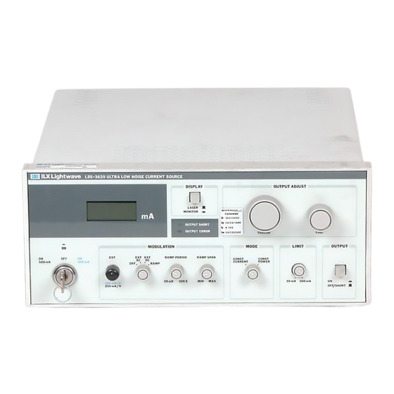
Page 14: Front Panel Controls And Connectors
Refer to Figure 2.1. 2.3.1 DC POWER Key Switch and Output Range Selection A three position key switch on the front panel of the LDX-3620 controls the power to the current source circuits: * Off ..................center position * 200 mA .............. -
Page 15: Ramp Modulation
Section 2.5.8. 2.3.7 OUTPUT On/Off The current output of the LDX-3620 is shorted by a mechanical switch and a JFET when the front panel OUTPUT push button switch is in the OFF/SHORT position (out). When the OUTPUT switch is set to the ON position, the short is removed and the JFET is turned off slowly. -
Page 16: Output Adjust Controls
2.3.8 OUTPUT ADJUST Controls The OUTPUT ADJUST, COARSE, and FINE knobs set the DC output level of the LDX-3620. The DC bias level is summed with the control signals derived from the MODULATION section to determine the final output level. -
Page 17: Output Short Indicator
*The output has reached the current LIMIT level, set by the LIMIT adjustment. *The output circuit is open. *The maximum compliance voltage of the LDX-3620 is insufficient to drive the load. Table 2.1 lists the possible conditions leading to a lighted OUTPUT ERROR LED:... -
Page 18: Rear Panel Controls And Connectors
LOW bandwidth position is selected, and it is disconnected when the HIGH bandwidth position is selected. In the HIGH position the modulated output bandwidth of the LDX-3620 is 1 MHz. With the switch in the LOW position the bandwidth across a 100 ohm load is cut to about 20 kHz. The LOW setting decreases noise and prevents oscillation of the LDX-3620 when it is connected to an inductive load, such as a bias "tee"... -
Page 19: Photodiode Feedback Gain Adjustments
LDX-3620 current output when the switch is opened. See Section 2.5.4 for instructions on the connection of an interlock switch. 2.4.3 PHOTODIODE Feedback Gain Adjustments The photodiode feedback circuit gain is adjustable on the rear panel to accept full-scale feedback currents from 20 uA to 1 mA. -
Page 20: Ramp Trigger Output Jack
Chassis ground is available on the rear of the unit through a banana jack connected to the LDX-3620 cabinet. When a three-wire line cord with earth-ground is used, the cabinet of the LDX-3620 is connected to the ground lead of the power cord. - Page 21 Figure 2.2 LDX-3620 Rear Panel Figure 2.3 Output Connector Pin-out...
-
Page 22: Ldx-3620 Operation Procedures
This section contains recommended procedures for operation of the LDX-3620 with a laser diode. It assumes that the batteries are adequately charged or that AC power is connected and on. -
Page 23: Load Considerations
(R = E / I) 3.2 V / 0.1 A = 32 ohms. If the LDX-3620 is to be used with an inductive load, such as a bias "tee" network, the LOW BANDWIDTH setting should be used. This is done to prevent possible oscillation of the LDX-3620. -
Page 24: Safe Settings
Table 2.2 LDX-3620 Recommended Safe Initial Settings 2.5.4 Safety Interlock Connections A safety interlock connection is available on pins 1 and 2 of the LDX-3620 rear panel OUTPUT connector. These pins must be shorted to enable the LDX-3620 current output. - Page 25 The LDX-3620 output is available through the 9-pin rear panel OUTPUT connector J401 (see Figure 2.3). The LDX-3620 sources current through pins 8 and 9 to the laser anode (+) and returns current from the cathode (-) through pins 4 and 5.
-
Page 26: Ramp Trigger Output Connections
(pins 4 and 5 of J401). The circuit of Figure 2.4B should be used, if feasible. 2.5.7 RAMP TRIGger Output Connections Two optically isolated RAMP TRIGGER outputs are provided on the LDX-3620 rear panel. The OSCILLOSCOPE output provides a voltage square pulse of up to 200 mV amplitude that is synchronized to the start and end of the output current ramp. - Page 27 Instrument OUTPUT Bias P. D. L. D. Earth Ground Figure 2.4A Common Laser Cathode - Photodiode Cathode Module OUTPUT Bias P. D. L. D. Earth Ground Figure 2.4B Common Laser Cathode - Photodiode Anode...
- Page 28 Module OUTPUT Bias P. D. L. D. Earth Ground Figure 2.1 C Common Laser Anode - Photodiode Cathode Module OUTPUT Bias P. D. L. D. Earth Ground Figure 2.1 D Common Laser Anode - Photodiode Anode...
-
Page 29: Setting The Limit Current
The displayed current is being delivered to the load. 2.5.10 Setting the MODULATION Controls The current output of the LDX-3620 can be controlled by an external voltage waveform. The transfer function of the modulation is 100 mA/V when the 200 mA output range is selected with the DC POWER key switch, or 250 mA/V when the 500 mA range is selected. -
Page 30: Using The Internal Ramp Generator
Set any desired offset DC output current with the OUTPUT ADJUST knobs. The display reads the average current delivered to the load. 2.5.12 Setting the Photodiode Feedback Gain The gain of the photodiode feedback circuit should be adjusted before operating the LDX-3620 in CONST POWER mode. - Page 31 IMPORTANT The LIMIT current level MUST be correctly set before switching the MODE selector to CONST POWER and turning the OUTPUT switch ON (in). Laser damage will result if the current level is not safely set. See Section 2.5.8 for setting the LIMIT current.
- Page 32 d) Push the OUTPUT switch to the ON position (in). e) Repeat Step 7. By alternately increasing the COARSE and FINE OUTPUT ADJUST knob settings and decreasing the FINE photodiode feedback gain trimmer, a full scale setting of the OUTPUT ADJUST knobs (both fully clockwise) can be made to deliver the desired maximum output power level.
-
Page 33: Setting The Laser Power In Const Power Mode
2.5.13 Setting the Laser Power in CONST POWER Mode Whenever the MODE selector switch is in the CONST POWER position, the LDX-3620 maintains the output optical power in proportion to the control signals derived from the MODULATION and OUTPUT ADJUST sections of the front panel. After the photodiode feedback gain has been successfully adjusted, the output optical power level can be set: Set the OUTPUT switch to OFF/SHORT (out). -
Page 35: Chapter 3 - Maintenance
If the LDX-3620 is to be stored for long periods, the batteries should be fully recharged for eight hours every 6-9 months to prevent a permanent loss of capacity due to self-discharge. -
Page 36: Battery Replacement
The transformer lugs are numbered 1 to 6, with lug 1 being nearest the mounting legs on the side-rail of the LDX-3620. The transformer wiring is accessed by removing the bottom pan of the instrument. See Figure 3.1 for the correct AC line connections. -
Page 37: Fuse Replacement
3.5 Fuse Replacement The AC power fuse is located on the rear panel of the LDX-3620. Should replacement be necessary, first disconnect the power cord and turn the AC POWER switch OFF. Refer to Table 3.2 for the correct fuse ratings. -
Page 38: Calibration
3.6.1 Display Calibration Connect the ammeter across the current output of the LDX-3620 to monitor the output current. Make the following settings and adjustments: Release the DISPLAY push button to the LASER position (out). -
Page 39: Monitor Current Display Calibration
(negative) value of the current input to the photodiode feedback pins 6 and 7 of the rear panel 9-pin connector (J401). After the display has been calibrated (see Section 3.6.1), the LDX-3620 can be used to source 1 mA to the series combination of the photodiode feedback input and calibration ammeter. -
Page 40: Output Adjust Calibration
Section 2.5.8. Turn the OUTPUT ADJUST knobs fully counter-clockwise (CCW) to their minimum setting and change the output current range to 200 mA with the DC power key switch. Connect an oscilloscope to a resistor load connected across the LDX-3620... -
Page 41: Disassembly
3.7 Disassembly The top cover of the LDX-3620 can be removed after extracting the two countersunk screws on the sides of the instrument near the rear panel. The cover is then removed by sliding it... -
Page 42: Index
Index AC coupled modulation ......................5, 20 AC power connections ........................... 11 fuse replacement ........................29 line voltage selection ......................28 operation ..........................4, 11 Bandwidth LOW ..........................10, 14 selector switch ........................10 specification ..........................2 Battery lifetime ..........................31-32 "long-life"... - Page 43 indication ..........................7 shutdown ..........................7 MODE selector switch ....................... 6, 27 Modulation external AC and DC coupled ................... 5, 20 internal ramp ........................6, 21 Operation procedures AC power operation ......................4, 11 connections and shielding ..................11, 15-17 CONSTANT POWER operation ................
Need help?
Do you have a question about the LDX-3620 and is the answer not in the manual?
Questions and answers