Table of Contents
Advertisement
Quick Links
Advertisement
Table of Contents

Related Manuals for ILX Lightwave LDX-3620B


Summary of Contents for ILX Lightwave LDX-3620B
-
Page 3: Table Of Contents
Tilt Foot Adjustment ..........3 Operating the LDX-3620B Ultra Low Noise Current Source ....3 Rear Panel Controls and Connectors . - Page 4 Operation Applying Power to Your LDX-3620B ....... . . 9 Battery Charging .
- Page 5 Chapter 3 Maintenance and Calibration Battery Maintenance ..........25 Battery Replacement .
- Page 7 Figure 1.1 LDX-3620B Front Panel ......4 Figure 1.2 LDX-3620B Rear Panel ......5 Figure 2.1 Common Laser Cathode - Photodiode Cathode .
-
Page 9: Safety And Warranty Information
• Prolonged storage under adverse conditions • Failure to perform intended measurements or functions If necessary, return the instrument to ILX Lightwave, or authorized local ILX Lightwave distributor, for service or repair to ensure that safety features are maintained (see the contact information later in this section.) -
Page 10: Safety Symbols
AFETY YMBOLS This section describes the safety symbols and classifications. Technical specifications including electrical ratings and weight are included within the manual. See the Table of Contents to locate the specifications and other product information. The following classifications are standard across all ILX Lightwave products: •... -
Page 11: Warranty
Returning an Instrument If an instrument is to be shipped to ILX Lightwave for repair or service, be sure to: Obtain a Return Authorization number (RA) from ILX Customer Service. -
Page 12: Comments, Suggestions, And Problems
You must negotiate and settle with the carrier for the amount of damage. Comments, Suggestions, and Problems To ensure that you get the most out of your ILX Lightwave product, we ask that you direct any product operation or service related questions or comments to ILX Lightwave Customer Support. - Page 13 If ILX Lightwave determines that a return to the factory is necessary, you are issued a Return Authorization (RA) number. Please mark this number on the outside of the shipping box. You or your shipping service are responsible for any shipping damage when returning the instrument to ILX Lightwave;...
-
Page 15: Product Overview
Severe transport stress Prolonged storage under adverse conditions Failure to perform intended measurements or functions If necessary, return the LDX-3620B to ILX Lightwave for service and repair to ensure that safety features are maintained. Product Overview The LDX-3620B is a battery powered, ultra low noise current source, optimized for narrow linewidth or stable wavelength laser diode applications. -
Page 16: Initial Inspection
Installing Your LDX-3620B Ultra Low Noise Current Source Power Requirements The LDX-3620B is a battery powered current source. It can be operated for up to 16 hours before recharging the batteries. A low voltage DC power supply (supplied with the instrument) is required to charge the batteries. The DC power... -
Page 17: Tilt Foot Adjustment
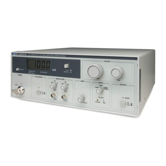
The supplied low voltage DC power supply is for use with the LDX-3620B Ultra Low Noise Current Source only. Do not use this power supply for any purpose other than running the LDX-3620B. - Page 18 Figure 1.1 LDX-3620B Front Panel Figure 1.2 LDX-3620B Rear Panel...
-
Page 19: Rear Panel Controls And Connectors
The rear panel 9-pin D-sub connector pin-outs are shown in Figure 2.5 in Chapter 2. The LDX-3620B output current is sourced (+) from pins 8 and 9 and the current returned (-) to pins 4 and 5. The monitor photodiode feedback current is input to pin 7 (+) and returned from pin 6 (-). -
Page 20: Specifications
Specifications... -
Page 21: Options And Accessories
Options and Accessories Options and accessories available for the LDX-3620B Ultra Low Noise Current Source include the following: MODEL NUMBER DESCRIPTION CC-305S Current Source Interconnect Cable, terminated, 6’ CC-306S Current Source Interconnect Cable, unterminated, 6’ CC-355S Current Source Cable, terminated, 5m... -
Page 23: Applying Power To Your Ldx-3620B
This chapter introduces you to the operation of the LDX-3620B Laser Diode Current Source. It offers instructions for connecting your laser to the current source, and describes powering up the instrument. This chapter also contains step by step procedures that teach you how to operate the current source in Constant Current Mode and Constant Power Mode. -
Page 24: Battery Charging
BATTERY push button is pushed, the batteries are in a low battery condition. Continued operation of the instrument in this condition is not recommended. The LDX-3620B uses two batteries; a large +12V battery for output current and driving active components and a second, smaller -12V battery for active components. - Page 25 (the front panel output switch in the OFF/SHORT position). Figures 2.1 through 2.4 show the possible configurations of connecting laser diodes and photodiodes with the LDX-3620B Ultra Low Noise Laser Diode Current Source.
- Page 26 Figure 2.1 Common Laser Cathode - Photodiode Cathode Figure 2.2 Common Laser Cathode - Photodiode Anode Figure 2.3 Common Laser Anode - Photodiode Cathode...
- Page 27 Figure 2.4 Common Laser Anode - Photodiode Anode The 9-pin connector marked Current Source on the back panel is used to connect your laser diode to the LDX-3620B. there are connections provided for laser cathode and anode, photodiode cathode and anode, chassis ground and interlock.
-
Page 28: Load Considerations
R = V/T = (5 - 1.8 V) / 0.1A = 32 ohms. If the LDX-3620B is to be used with an inductive load, such as a bias “tee” network, the instrument mode should be set to constant current, low bandwidth. This is done to prevent possible oscillation of the current source. - Page 29 The feedback photodiode reverse-biasing supply shown in these figures must be supplied by the user. It is located in the circuit where it will not cause the common mode voltage of the feedback inputs to exceed their specified maximum of +6 volts, relative to the "-"...
-
Page 30: Front Panel Operation
POWER switch in 200 mA range or the 500 mA range. See the section "Applying Power to the LDX-3620B" at the beginning of this chapter for information on the power switch and selecting the current source output range. -
Page 31: Display Selector
BATTERY Charge Indicator The LDX-3620B includes an LED battery life indicator on the front panel. To check approximate battery life, press the BATTERY button located underneath the four LED's on the left of the display. The LED bars will illuminate based on measured battery voltage. -
Page 32: Charge Switch
LED above the switch will light up indicating that the batteries are charging. With this switch disabled, the LDX-3620B draws power from its internal batteries. For lowest noise operation, the CHARGE switch should be disabled. The instrument can be operated in any mode on battery only or while the batteries are charging. -
Page 33: Limit Current Adjustment
In CONST POWER mode, the LDX-3620B uses a feedback signal from a photodiode to set the output current level to maintain a constant optical power at the load. -
Page 34: Output On/Off
MODULATION control signals. Photodiode Feedback Gain Adjustments Setting the gain of the photodiode feedback signal allows the LDX-3620B to operate in a closed loop fashion in constant power mode to maintain any operating power point (within the safe operating limits of the laser) by controlling laser current to the laser diode. - Page 35 20 uA and 2mA. For example, if the maximum back facet monitor current from the laser diode was 400 uA, the maximum set point could be adjusted to be 400 uA. By providing the gain adjustment the LDX-3620B is an ideal instrument for maximum setpoint resolution when operating in constant current mode.
- Page 36 To adjust the photodiode feedback gain, follow the procedure listed below. Set the front panel controls of the LDX-3620B to the safe initial settings summarized in Table 2.1. Including setting the LDX-3620B initially in a constant current mode of operation.
-
Page 37: Modulating The Output Current
Modulating the Output Current The current output of the LDX-3620B can be controlled by an external voltage source; either a DC signal or an alternating waveform. One or two external voltage wave forms can be used to modulate the output current through the input ports labeled EXT1 and EXT2. -
Page 38: Output Error Indicators
Output Error Indicators CURRENT LIMIT Indicator The CURRENT LIMIT indicator is illuminated whenever current set point exceeds the current limit as set by the LIMIT knob. Output will remain on, but the output current will not exceed the limit setting. OVER VOLTAGE Indicator The OVER VOLTAGE indicator will illuminate whenever the load voltage exceeds 5V on the output of the laser diode. -
Page 39: Battery Maintenance
LDX-3620B in good operating condition. Battery Maintenance The battery life of the LDX-3620B depends on the frequency and degree of discharge of the batteries during use. With light use and proper maintenance, the batteries should last for more than 1100 recharge cycles (about four years of daily use). -
Page 40: Battery Replacement
The batteries may be replaced by removing the top chassis cover, which is held in place with 4 6-32 machine screws. For replacement batteries in the US please contact ILX Lightwave. For regions outside of the US please contact your local ILX distributor. See the following sections for disassembly instructions. -
Page 41: Fuse Replacement
These fuses can be seen in Figure 3.2. The TR5 fuses are rated for 1.25A, 250V Figure 3.2 TR5 Fuse Replacement Position If you are unable to obtain replacement fuses, please contact ILX Lightwave or your local distributor for replacements. -
Page 42: Calibration
Calibration The following paragraphs outline the procedures for calibrating the instrument. Access to the adjustment trimpots on the circuit boards will require that the top of the instrument be removed. The removal procedure is discussed later in this chapter. The equipment required for the calibration procedures must be capable of measuring a current of 500mA to an accuracy of approximately 0.01mA and measuring 2mA to an accuracy of 0.00005mA. - Page 43 Figure 3.3 200 mA Calibration Potentiometer Position Figure 3.4 Photodiode and 500 mA Measurement Calibration Position...
-
Page 44: Laser Diode Measurement Calibration
1 hour (the instrument can be calibrated in DC or AC mode of operation): Connect a 20-25 ohm load resistor on the output of the LDX-3620B. Connect a digital ammeter discussed earlier in this section in series with the output of the laser diode and the test load. -
Page 45: Disassembly
Disassembly The top cover of the LDX-3620B can be removed after extracting the four countersunk screws on the sides of the instrument. The cover is then removed by sliding it rearward and lifting it off. Removal of the top chassis cover can be seen in Figure 3.5. - Page 47 This appendix is a guide to troubleshooting the LDX-3620B Ultra Low-Noise Current Source. Some of the more common symptoms are listed here, and the appropriate troubleshooting actions are given. We recommend that the user start at the beginning of this guide. Read the symptom descriptions, and follow the steps for the corrective actions which apply.