
Related Manuals for Allied Telesis AT-IE300-12GP


Summary of Contents for Allied Telesis AT-IE300-12GP
- Page 1 IE300 Series Industrial Ethernet Switches AT-IE300-12GT AT-IE300-12GP Installation Guide 613-002041 Rev. C...
- Page 2 Allied Telesis, Inc. has been advised of, known, or should have known, the...
- Page 3 European Union Restriction of the Use of Certain Hazardous Substances (RoHS) in Electrical and Electronic Equipment This Allied Telesis RoHS-compliant product conforms to the European Union Restriction of the Use of Certain Hazardous Substances (RoHS) in Electrical and Electronic Equipment. Allied Telesis ensures RoHS conformance by requiring supplier Declarations of Conformity, monitoring incoming materials, and maintaining manufacturing process controls.
- Page 4 IE300 Series Installation Guide Regulatory Approvals The regulatory approvals of the product are listed here: Safety UL/IEC/EN 60950-1 UL/IEC/EN 60950-22 CAN/CSA-22.2: 60950-1 CAN/CSA-22.2: 60950-22 CE, FCC Part 15 Class A EN55032 (CISPR32) Class A EN61000-3-2 EN61000-3-3 EN55024 EN61000-4-2 EN61000-4-3 EN61000-4-4 EN61000-4-5 EN61000-4-6 EN61000-4-8...
- Page 5 IE300 Series Installation Guide Allied Telesis approved SFP modules EN60825-1 EN60825-2 UL/IEC/EN60950-1 FDA CDRH accession registration Warning: In a domestic environment this product may cause radio interference in which case the user may be required to take adequate measures. Laser Safety...
-
Page 7: Table Of Contents
Contents Preface ....................................13 Safety Symbols Used in this Document ........................14 Contacting Allied Telesis ..............................15 Overview ....................................17 Hardware Components ..............................18 Features ..................................21 Twisted Pair Ports ..............................21 Power Over Ethernet.............................21 SFP Slots ................................21 LEDs ..................................22 Alarm Connectors ..............................22 MAC Address Tables ............................22 Management Software ............................22... - Page 8 Verifying Switch Operations ..........................97 Monitoring the Initialization Process ..........................98 Starting a Local Management Session ........................100 Verifying the AT-IE300-12GP Switch......................... 102 Verifying the PoE Budget ........................... 102 Configuring Alternatives A and B ........................103 Configuring the Provisioned PoE Budget ......................104 Installing the Optional Drip Guard..........................
- Page 9 Figure 7: Example of the Alarm Out Port..........................40 Figure 8: Twisted Pair Port LEDs on the AT-IE300-12GT Switch ..................42 Figure 9: Twisted Pair Ports on the AT-IE300-12GP Switch ....................43 Figure 10: Optional Drip Guard.............................49 Figure 11: Pre-installed Components on the Front Panel.....................59 Figure 12: Pre-installed Components on the Top Panel.......................60...
- Page 10 Figures Figure 50: Installing the Optional Drip Guard........................107 Figure 51: Securing the Drip Guard ............................108 Figure 52: RJ-45 Port Pin Layout (Front View) ........................123 Figure 53: Console Port Pin Layout (Front View) .......................125...
- Page 11 Table 24: RJ-45 Style Console Port Pin Signals .......................125 Table 25: PWR 1 and PWR 2 DC Connector Pin Signals on the AT-IE300-12GT Switch ..........126 Table 26: PWR 1 and PWR 2 DC Connector Pin Signals on the AT-IE300-12GP Switch ..........126...
- Page 12 Tables...
-
Page 13: Preface
Preface This guide contains the hardware installation instructions for the IE300 Series of industrial managed switches. The preface contains the following sections: “Safety Symbols Used in this Document” on page 14 “Contacting Allied Telesis” on page 15 ... -
Page 14: Safety Symbols Used In This Document
Preface Safety Symbols Used in this Document This document uses the following conventions. Note Notes provide additional information. Caution Cautions inform you that performing or omitting a specific action may result in equipment damage or loss of data. Warning Warnings inform you that performing or omitting a specific action may result in bodily injury. -
Page 15: Contacting Allied Telesis
IE300 Series Installation Guide Contacting Allied Telesis If you need assistance with this product, you may contact Allied Telesis technical support by going to the Support & Services section of the Allied Telesis web site at www.alliedtelesis.com/support. You can find links for the following services on this page: 24/7 Online Support —... - Page 16 Preface...
-
Page 17: Overview
Chapter 1 Overview This chapter describes the hardware features of the IE300 Series of managed industrial switches. The sections in the chapter are listed here: “Hardware Components” on page 18 “Features” on page 21 “10/100/1000Base-T Twisted Pair Ports” on page 24 ... -
Page 18: Hardware Components
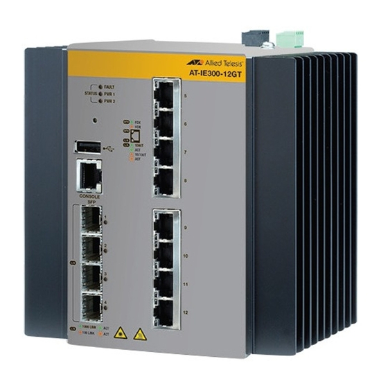
Status LEDs Reset button USB port Console 10/100/1000Base-T management twisted pair ports port Slots for 100/1000Base-FX SFP transceivers Figure 1. Front Panel of the AT-IE300-12GT Switch The front panel of the AT-IE300-12GP Switch is shown in Figure 2 on page 19. -
Page 19: Figure 2: Front Panel Of The At-Ie300-12Gp Switch
Slots for with PoE, PoE+, and 100/1000Base-FX Hi-PoE SFP transceivers Figure 2. Front Panel of the AT-IE300-12GP Switch Figure 3 identifies the components on the top panel. Alarm In Grounding screw connector PWR 1 DC power connector... -
Page 20: Figure 4: Back Panel Features
Chapter 1: Overview Figure 4 on page 20 identifies the components on the back panel. Screw holes for wall bracket DIN rail bracket Screw holes for wall bracket Figure 4. Back Panel Features... -
Page 21: Features
Jumbo frames up to 9KB RJ-45 connectors Power Over Ports 5 to 12 on the AT-IE300-12GP Switch have these Power over Ethernet features: Ethernet Ports 5 to 8 support PoE (15 watts) and PoE+ (30 watts) Ports 9 to 12 support PoE, PoE+, and Hi-PoE (60 watts) ... -
Page 22: Leds
AT-IE300-12GP Switch. Link/activity LEDs for the SFP ports. Fault and power supply status LEDs PoE LEDs on the AT-IE300-12GP Switch Alarm The switches have two alarm connectors: Connectors Alarm In connector for an external sensor, such as a motion ... - Page 23 IE300 Series Installation Guide Two DC power supply connectors Extended environmental range IP30-compliant without optional drip guard IP31-compliant with optional drip guard RJ-45 style Console port for local management ...
-
Page 24: 10/100/1000Base-T Twisted Pair Ports
Chapter 1: Overview 10/100/1000Base-T Twisted Pair Ports This section describes the twisted pair ports. Connector Type The twisted-pair ports have 8-pin RJ-45 connectors. The ports use four pins at 10 or 100 Mbps and all eight pins at 1000 Mbps. The pin assignments are listed in Table 22 on page 123 and Table 23 on page 123. -
Page 25: Automatic Mdix Detection
IE300 Series Installation Guide Table 1. Twisted Pair Cable for the AT-IE300-12GT Switch Cable Type 10Mbps 100Mbps 1000Mbps Standard TIA/EIA 568-B- compliant Category 3 shielded or unshielded cabling with 100 ohm impedance and a frequency of 16 MHz. Standard TIA/EIA 568-A- compliant Category 5 or TIA/ EIA 568-B-compliant Enhanced Category 5 (Cat 5e) shielded or... -
Page 26: Power Over Ethernet
Chapter 1: Overview Power over Ethernet Ports 5 to 12 on the AT-IE300-12GP Switch support Power over Ethernet (PoE). With PoE, the switch can supply electrical power to network devices over the same twisted pair cables that carry network traffic. The... -
Page 27: Powered Device Classes For Poe And Poe
The PoE and PoE+ standards define five powered device classes. The classes are defined by the power requirements of the powered devices. Classes for PoE The classes are shown in Table 4 on page 27. The AT-IE300-12GP and PoE+ Switch supports all five classes. -
Page 28: Power Delivery With Alternatives A And B
PDs that are non-standard or were manufactured before the completion of the standards might support only one method. The AT-IE300-12GP Switch supports Alternatives A and B on the twisted pair ports as follows: Port 5 to 8 - Alternative A only ... - Page 29 IE300 Series Installation Guide Here are the default settings for Alternatives A and B on the switch: For ports 5 to 8 the default setting for Alternative A is enabled. For ports 9 to 12 the default settings are enabled for Alternative A ...
-
Page 30: Poe Budget
PoE Budget The AT-IE300-12GP Switch has a PoE budget. This is the total wattage the switch has available for the powered devices on its ports. The maximum possible budget is 240W. The PoE budget can never be more than that, but it can be less, depending on the DC power supply. - Page 31 IE300 Series Installation Guide Critical ports are receiving power. Ports that are connected to your most critical powered devices should be assigned to this level. If there is not enough power to support all the ports set to the Critical priority level, power is provided to the ports based on port number, in ascending order.
-
Page 32: Sfp Slots
Chapter 1: Overview SFP Slots The four slots support Ethernet 100/1000Base fiber optic, MSA-compliant SFP transceivers. You can use transceivers to connect switches to other network devices over large distances, build a high-speed backbone network between network devices, or connect high-speed devices, such as servers, to your network. -
Page 33: Console Port
IE300 Series Installation Guide Console Port The Console port is a serial RS-232 port you use to access the AlliedWare Plus management software to configure the features. Management sessions conducted through the Console port are called local management sessions because you have to be at the location of the switch. -
Page 34: Usb Port
Chapter 1: Overview USB Port The USB port supports a flash drive for the following management functions: Use Allied Telesis Management Framework to provide a centralized network backup location. Store backup copies of configuration files. Transfer configuration files between switches. -
Page 35: Ground Screw
The power supply requirements are described in “Power Supplies” on page 48. Allied Telesis does not sell or provide power supplies for this product. They must be purchased from another equipment manufacturer. Note The AT-iMG008 Power Supply and Backup Unit from Allied Telesis... -
Page 36: Alarm In Connector
Chapter 1: Overview Alarm In Connector The switch has a 2-pin Alarm In (ALM IN) connector for an external sensor on the top panel. The switch can use an external sensor to monitor the wiring room or cabinet for unauthorized access or for changes in the room’s environment, such as the temperature or humidity. -
Page 37: Figure 5: Example 1 Of The Alarm In (Alm In) Connector
IE300 Series Installation Guide The example in Figure 5 shows the Alarm In connector attached to a door sensor. The sensor is installed such that it is closed (on) when the door is closed and open (off) when the door is open. Door Sensor: Alarm In connector: Door closed - circuit closed... -
Page 38: Figure 6: Example 2 Of The Alarm In (Alm In) Connector
The command configures the switch to signal the alarm when the sensor changes to closed above 30° C. When the temperature falls below 30° C, and the temperature sensor changes from closed to open, the switch automatically cancels the alarm. External sensors are not available from Allied Telesis. -
Page 39: Alarm Out Connector
IE300 Series Installation Guide Alarm Out Connector The 2-pin Alarm Out connector on the top panel of the switch is for an external alert device. The switch can use the device to alert you to alarm conditions, such as power supply failures or ports without links. Here are two examples of alert devices for the Alarm Out connector: LEDs ... -
Page 40: Din Rail Bracket
The alert device, detecting the change to the circuit, turns on the LED. When the switch detects that all its ports have links again, it closes the circuit, which turns off the LED. Alarm devices are not available from Allied Telesis. Blue LED Circuit closed - LED off Circuit open - LED on Figure 7. -
Page 41: Leds
IE300 Series Installation Guide LEDs The following sections describe the LEDs on the switches: “Status LEDs” on page 41 “Twisted Pair Port LEDs” on page 42 “SFP Slot LEDs” on page 44 “PoE Status LEDs” on page 45 ... -
Page 42: Twisted Pair Port Leds
Chapter 1: Overview Table 6. Status LEDs (Continued) State Description Solid Green The switch is receiving power on the PWR 1 connector and is operating normally. PWR2 The switch is not receiving power on the PWR 2 connector or the input power from the DC power supply is outside the normal operating range of the unit. -
Page 43: Figure 9: Twisted Pair Ports On The At-Ie300-12Gp Switch
The LEDs are identified in Figure 9. Power over Ethernet Speed and activity Figure 9. Twisted Pair Ports on the AT-IE300-12GP Switch The states of the LEDs on the twisted pair ports on the AT-IE300-12GP Switch are defined in Table 8 on page 44. -
Page 44: Sfp Slot Leds
Chapter 1: Overview Table 8. Twisted Pair Port LEDs on the AT-IE300-12GP Switch State Description Solid Green The port is delivering power to a powered device. Solid Amber The port is connected to a powered device but the switch has shutdown PoE on it because of a fault condition. -
Page 45: Poe Status Leds
Hi-PoE devices, use the SHOW POWER-INLINE command in the User Exec or Privileged Exec mode. Devices using more than 25.9W are considered Hi-PoE devices. The PoE status LEDs on the AT-IE300-12GP Switch are defined in Table 10. Table 10. PoE Status LEDs... - Page 46 Chapter 1: Overview Table 10. PoE Status LEDs (Continued) State Description Optimal Green The switch has the maximum amount of power for powered devices. The default value is 240W. You can adjust this value with the POWER-INLINE WATTAGE MAX command in the User Exec or Privileged Exec mode.
- Page 47 IE300 Series Installation Guide Table 10. PoE Status LEDs (Continued) State Description No PoE Solid amber The switch cannot support any powered devices on its ports because it is not receiving sufficient power from the power supply. Possible causes of this condition are listed here: - The power supply is experiencing a problem.
-
Page 48: Power Supplies
240W of power for powered devices. Adding a second power supply adds system and PoE power redundancy. Note A 48VDC power supply for the AT-IE300-12GP Switch must have an absolute maximum tolerance of +2.5% when adjusted to 53.5VDC at the input to the switch, to provide full Hi-PoE power. -
Page 49: Optional Drip Guard
IE300 Series Installation Guide Optional Drip Guard Allied Telesis offers an optional drip guard for the switch. Refer to Figure 10. The switch with the drip guard has an ingress protection (IP) code of IP31. Figure 10. Optional Drip Guard... - Page 50 Chapter 1: Overview...
-
Page 51: Beginning The Installation
Chapter 2 Beginning the Installation The chapter contains the following sections: “Reviewing Safety Precautions” on page 52 “Safety Precautions When Working with Electricity” on page 56 “Reviewing Site Requirements” on page 57 “Verifying the Package Contents” on page 59 ... -
Page 52: Reviewing Safety Precautions
Chapter 2: Beginning the Installation Reviewing Safety Precautions Please review the following safety precautions before beginning the installation procedures. Note Safety statements that have the symbol are translated into multiple languages in the Translated Safety Statements document at www.alliedtelesis.com/support. Warning Class 1 Laser product. - Page 53 IE300 Series Installation Guide Warning Power cord is used as a disconnection device. To de-energize equipment, disconnect the power cord. E3 Warning This equipment must be earthed. The ground screw on the unit must be connected to a properly earthed bonding point. Note Ground resistance from the building primary bonding point to earth should be less than 5 ohms.
- Page 54 Chapter 2: Beginning the Installation Warning To reduce the risk of electric shock, do not route network cables from PoE ports outside the building that houses this device. E40 Caution The unit does not contain serviceable components. Please return damaged units for servicing.
- Page 55 IE300 Series Installation Guide Warning Allied Telesis does not warrant against lightning or power surges causing damage the device. Such damage will be the responsibility of the equipment owner.
-
Page 56: Safety Precautions When Working With Electricity
Chapter 2: Beginning the Installation Safety Precautions When Working with Electricity Please review the following additional safety guidelines before beginning the installation procedure. Disconnect all power by turning off the circuit breakers before installing or removing the device or when working with the power supplies. -
Page 57: Reviewing Site Requirements
IE300 Series Installation Guide Reviewing Site Requirements Please observe the following requirements and guidelines when choosing a site for the switch: You can install the switch on a concrete wall, wooden wall, or DIN 35x7.5mm rail. You should not install the switch on a wall that has metal studs. ... -
Page 58: Table 11: Ground Resistivity Recommendations
Chapter 2: Beginning the Installation restrictions on site requirements, and to follow all guidelines and safety warnings. The switch and DC power source should be installed close to each other so that the DC power cables are kept as short as possible to minimize voltage loss. -
Page 59: Verifying The Package Contents
IE300 Series Installation Guide Verifying the Package Contents Figure 11 identifies the pre-installed components on the front panel of the switch. One dust cover on the USB port Nine dust covers on the twisted pair ports and Console port Four dust covers on the SFP slots Figure 11. -
Page 60: Figure 12: Pre-Installed Components On The Top Panel
Chapter 2: Beginning the Installation Figure 12 identifies the pre-installed components on the top panel. Two 2-pin connectors on the DC ALM IN and ALM OUT connectors One M4x8 Phillips-head grounding screw One 4-pin connector on the DC power PWR 1 and PWR 2 connector Figure 12. -
Page 61: Figure 13: Pre-Installed Component On The Back Panel
IE300 Series Installation Guide Figure 13 identifies the pre-installed component on the back panel. One DIN rail bracket Figure 13. Pre-installed Component on the Back Panel... -
Page 62: Figure 14: Components In The Accessory Kit
Chapter 2: Beginning the Installation Figure 14 lists the items included in the accessory kit that comes with the switch. Two wall brackets Five M4x8 Phillips-head screws One 2 m (6.6 ft) local management cable with RJ-45 (8P8C) and DB-9 (D-sub 9-pin) connectors Figure 14. -
Page 63: Installing The Switch
Chapter 3 Installing the Switch The procedures in this chapter are listed here: “Installing the Switch on a DIN Rail” on page 64 “Installing the Switch on a Wooden Wall” on page 67 “Installing the Switch on a Concrete Wall” on page 71 ... -
Page 64: Installing The Switch On A Din Rail
Chapter 3: Installing the Switch Installing the Switch on a DIN Rail The switch comes with a DIN rail bracket pre-installed on the back panel. The bracket is compatible with DIN 35x7.5mm rails. Figure 15 shows the proper orientation of the switch on a DIN rail. Do not install the switch horizontally or upside-down. -
Page 65: Figure 16: Installing The Switch On A Din Rail - 1
IE300 Series Installation Guide Slot in DIN rail bracket Top edge of DIN rail Figure 16. Installing the Switch on a DIN Rail - 1 2. Press on the bottom edge of the front faceplate of the switch until the bottom edge of the DIN rail snaps into the bottom slot in the bracket. -
Page 66: Figure 18: Verifying The Din Rail Installation
Allied Telesis recommends installing DIN rail end clamps to the sides of the switch to prevent damage or network traffic loss from vibration or shock. End clamps are not available from Allied Telesis. 4. Go to Chapter 4, “Cabling the Ports” on page 75. -
Page 67: Installing The Switch On A Wooden Wall
IE300 Series Installation Guide Installing the Switch on a Wooden Wall Allied Telesis recommends using a plywood base when installing the switch on a wall with wooden studs. The base allows you to mount the device on two studs in the wall. (A plywood base is not required for a concrete wall.) Refer to Figure 19. -
Page 68: Tools And Material
Chapter 3: Installing the Switch You should install the plywood base to the wall first and then install the switch on the base. Refer to Figure 20. Wall Studs Wall Plywood Base Step 2: Install the Step 1: Install the switch on the plywood base on plywood base. -
Page 69: Installing The Switch On The Plywood Base
IE300 Series Installation Guide The selected wall location for the base should adhere to the recommendations in “Reviewing Site Requirements” on page 57. Installing the This procedure assumes that the plywood base for the switch is installed on the wall. Please review “Reviewing Safety Precautions” on page 52 and Switch on the “Reviewing Site Requirements”... -
Page 70: Figure 22: Attaching The Switch To The Plywood Base
Chapter 3: Installing the Switch 3. Have another person hold the switch on the plywood base on the wall while you secure it with four screws (not provided). Refer to Figure 22. Please follow these guidelines as you position the switch on the wall: The switch must be oriented as shown in Figure 22. -
Page 71: Installing The Switch On A Concrete Wall
IE300 Series Installation Guide Installing the Switch on a Concrete Wall This section contains instructions on how to install the switch on a concrete wall. Warning The device is heavy. Always ask for assistance before moving or lifting it to avoid injuring yourself or damaging the equipment. Warning The device should be installed on a wall by a qualified building contractor. -
Page 72: Figure 23: Marking The Locations Of The Bracket Holes On A Concrete Wall
Prior to drilling, set the drill to hammer and rotation mode. The modes break up the concrete and clean out the hole. Allied Telesis recommends cleaning out the holes with a brush or compressed air. 6. Insert four anchors (not provided) into the holes. -
Page 73: Figure 24: Installing The Switch On A Concrete Wall
IE300 Series Installation Guide Figure 24. Installing the Switch on a Concrete Wall 8. Go to Chapter 4, “Cabling the Ports” on page 75. - Page 74 Chapter 3: Installing the Switch...
-
Page 75: Cabling The Ports
Chapter 4 Cabling the Ports This chapter contains the following procedures: “Cabling the Twisted Pair Ports” on page 76 “Installing SFP Transceivers” on page 78 ... -
Page 76: Cabling The Twisted Pair Ports
Chapter 4: Cabling the Ports Cabling the Twisted Pair Ports Here are the guidelines to cabling the 10/100/1000Base-T twisted pair ports on the cards: The ports have 8-pin RJ45 connectors. The cable specifications for the twisted pair ports on the AT-IE300- ... - Page 77 IE300 Series Installation Guide not support the feature. On those ports, you should disable automatic MDIX detection and set the wiring configuration manually with the POLARITY command. The appropriate MDI/MDI-X setting for a switch port connected to a 10/100Base-T network device with a fixed wiring configuration depends on the setting of the network device and whether the switch and network device are connected with straight-through or crossover cable.
-
Page 78: Installing Sfp Transceivers
Chapter 4: Cabling the Ports Installing SFP Transceivers Please review the following guidelines before installing SFP transceivers: SFP transceivers are hot-swappable. You may install them while the device is powered on. For a list of supported transceivers, refer to the product data sheet. ... -
Page 79: Figure 25: Removing The Dust Plug From An Sfp Slot
IE300 Series Installation Guide Figure 25. Removing the Dust Plug from an SFP Slot 2. Remove the transceiver from its shipping container and store the packaging material in a safe location. 3. Position the transceiver with its handle on the right and slide it into the slot until it clicks into place. -
Page 80: Figure 27: Removing The Dust Cover From An Sfp Transceiver
Chapter 4: Cabling the Ports Note If you are ready to attach the fiber optic cable to the transceiver, continue with the next step. Otherwise, repeat steps 1 to 3 to install the remaining transceivers in the switch. 4. Remove the dust cover from the transceiver. Refer to Figure 27. Figure 27. -
Page 81: Figure 29: Connecting A Fiber Optic Cable To An Sfp Transceiver
IE300 Series Installation Guide Figure 29. Connecting a Fiber Optic Cable to an SFP Transceiver 7. Repeat this procedure to install and cable the remaining transceivers. 8. Go to Chapter 5, “Powering On the Switch” on page 83. - Page 82 Chapter 4: Cabling the Ports...
-
Page 83: Powering On The Switch
“Powering On the Switch” on page 96 “Monitoring the Initialization Process” on page 98 “Starting a Local Management Session” on page 100 “Verifying the AT-IE300-12GP Switch” on page 102 “Installing the Optional Drip Guard” on page 107 ... -
Page 84: Connecting The Grounding Wire
Chapter 5: Powering On the Switch Connecting the Grounding Wire Here are the guidelines for the grounding wire: The wire should be minimum #16 AWG solid wire. The wire length should be as short as possible. Continuity from the grounding screw to the earth ground must be ... -
Page 85: Figure 31: Loosening The Grounding Screw
IE300 Series Installation Guide Figure 31. Loosening the Grounding Screw 3. Wrap the grounding wire clockwise around the base of the grounding screw. Refer to Figure 32. Figure 32. Wrapping the Grounding Wire Around the Grounding Screw... -
Page 86: Figure 33: Securing The Grounding Wire To The Switch
Chapter 5: Powering On the Switch 4. Tighten the screw to secure the grounding wire to the switch. Refer to Figure 33. Figure 33. Securing the Grounding Wire to the Switch 5. Connect the other end of the ground wire to a ground point at the installation site. -
Page 87: Wiring The Alm In And Alm Out Connectors
IE300 Series Installation Guide Wiring the ALM IN and ALM OUT Connectors For background information on the alarm connectors, refer to “Alarm In Connector” on page 36 and “Alarm Out Connector” on page 39. Here are general guidelines to the alarm connectors: Use 24 to 18 AWG stranded wire properly rated for the installation ... -
Page 88: Figure 34: Polarity Legend For The Alarm Connectors
Chapter 5: Powering On the Switch Before wiring an alarm connector, familiarize yourself with the negative and positive polarities of its two pins by examining the legends on the top panel. Refer to Figure 34. Figure 34. Polarity Legend for the Alarm Connectors The following procedure shows the ALM OUT connector. -
Page 89: Figure 36: Wrapping The Wire Strands
IE300 Series Installation Guide Figure 36. Wrapping the Wire Strands Note Allied Telesis recommends that you also tin the wires with solder as added protection against loose strands. This guide does not provide instructions on how to tin wires. 3. Remove the alarm connector from the top panel. Figure 37 shows the removal of the ALM OUT connector. -
Page 90: Figure 39: Inserting The Wires Into The Dc Cable Connector
Chapter 5: Powering On the Switch 5. Insert the wires into the connector and tighten the retaining screws to secure the wires. Refer to Figure 39. Allied Telesis recommends tightening the screws to 2 to 3 in.-lbs. Positive (+) Negative (-) Figure 39. -
Page 91: Figure 40: Inserting The Dc Connector Into The Alarm Connector
IE300 Series Installation Guide Figure 40. Inserting the DC Connector into the Alarm Connector 8. Connect the other end of the wires to an external sensor for the Alarm In connector or an alert device for the Alarm Out connector. 9. -
Page 92: Preparing The Dc Power Cables
Chapter 5: Powering On the Switch Preparing the DC Power Cables You can power the switch with either one or two DC power supplies. For power supply specifications, refer to “Power Supplies” on page 48. Power supplies are connected to the 4-wire, DC power connector on the top panel of the switch. -
Page 93: Figure 42: Stripping A Power Cable Wire
This step is to prevent loose strands from touching other wires and causing an electrical short. Note Allied Telesis recommends that you also tin the wires with solder as added protection against loose strands. This guide does not provide instructions on how to tin wires. -
Page 94: Figure 44: Loosening The Wire Retaining Screws On The Pwr 1 - Pwr 2 Cable Connector
Cable Connector 5. Insert the wires into the connector and tighten the retaining screws to secure the wires. Refer to Figure 45. Allied Telesis recommends tightening the screws to 2 to 3 in.-lbs. PWR 1 PWR 2 Figure 45. Inserting the Wires into the PWR 1 - PWR 2 Cable Connector 6. -
Page 95: Figure 46: Verifying The Wire Installation
IE300 Series Installation Guide Incorrect - Loose wire Correct Incorrect - Exposed wire. strands Figure 46. Verifying the Wire Installation Warning Check to see if there are any exposed copper strands coming from the installed wires. When this installation is done correctly there should be no exposed copper wire strands extending from the terminal block. -
Page 96: Powering On The Switch
Chapter 5: Powering On the Switch Powering On the Switch This section contains the procedure for powering on the switch. Note The switch can update its release or configuration file from a USB flash drive during the initial power up of the unit. This is called the Autoboot feature. -
Page 97: Verifying Switch Operations
The Link LEDs are identified in Figure 8 on page 42 and Figure 9 on page 43. The PoE LEDs on the AT-IE300-12GP Switch should be solid green on ports that are connected to PoE, PoE+, or Hi-PoE devices. -
Page 98: Monitoring The Initialization Process
Verifying release... OK Booting... Starting base/first... [ OK ] Mounting virtual filesystems... [ OK ] Allied Telesis Inc. AlliedWare Plus (TM) v5.4.6 Current release filename: IE300-5.4.6-20160329-2.rel Built: Tue Mar 29 03:50:20 UTC 2016 Mounting static filesystems... [ OK ] Checking flash filesystem... -
Page 99: Figure 49: Initialization Messages (Continued)
IE300 Series Installation Guide Starting base/apteryx... [ OK ] starting base/appmond... [ OK ] Starting base/clockcheck... [ OK ] Starting hardware openhpi... [ OK ] Starting hardware/timeout... [ OK ] Starting base/inet... [ OK ] Starting base/modules... [ OK ] Received event modules.done Received event board.inserted Received event apteryx.done... -
Page 100: Starting A Local Management Session
Chapter 5: Powering On the Switch Starting a Local Management Session This section contains the procedure for starting a local management session on the switch. Please review the following information before performing the procedure: The initial management session with the switch must be a local ... - Page 101 installation steps are required. For instructions on how to configure the features, refer to the Software Reference for the IE300 Series Switches. If you are installing the AT-IE300-12GP Switch, go to “Verifying the AT-IE300-12GP Switch” on page 102.
-
Page 102: Verifying The At-Ie300-12Gp Switch
Chapter 5: Powering On the Switch Verifying the AT-IE300-12GP Switch This section contains the following procedures for the AT-IE300-12GP Switch: “Verifying the PoE Budget” on page 102 “Configuring Alternatives A and B” on page 103 “Configuring the Provisioned PoE Budget” on page 104 ... -
Page 103: Configuring Alternatives A And B
104. Configuring This procedure explains how to configure Alternatives A and B on ports 9 to 12 on the AT-IE300-12GP Switch, for Hi-PoE devices or legacy devices Alternatives A that only support Alternative B. The procedure does the following:... -
Page 104: Configuring The Provisioned Poe Budget
Chapter 5: Powering On the Switch 1. From the Privilege Exec mode, enter CONFIGURE TERMINAL to move to the Global Configuration mode: awplus# configure terminal awplus(config)# 2. Use the INTERFACE PORT command to move to the Port Interface modes of ports connected to Hi-PoE or legacy PoE devices. This example of the command moves into the Port Interface modes for ports 9 and 10: awplus(config)# interface port1.0.9-port1.0.10... - Page 105 IE300 Series Installation Guide The default nominal or provisioned PoE budget is 240W. The default value corresponds to the maximum PoE budget for power supplies that meet the specifications in “Power Supplies” on page 48. If you purchase a power supply that does not meet the specifications, the actual PoE budget may be less, in which case you should perform the following procedure to adjust the provisioned budget to match the actual value.
- Page 106 Chapter 5: Powering On the Switch The provisioned PoE budget of the switch is now set. Refer to the Software Reference for the IE300 Series Switches for management instructions.
-
Page 107: Installing The Optional Drip Guard
IE300 Series Installation Guide Installing the Optional Drip Guard To install the drip guard, perform the following procedure: 1. Slide the drip guard over the top of the switch. The front overhang on the drip guard should project over the front of the switch. Refer to Figure 50. -
Page 108: Figure 51: Securing The Drip Guard
Chapter 5: Powering On the Switch 2. Install the four Phillips-head screws included with the drip guard to secure it to the switch. Refer to Figure 51. Figure 51. Securing the Drip Guard... -
Page 109: Troubleshooting
“PWR 1 and PWR 2 LEDs” on page 110 “Twisted Pair Ports” on page 111 “SFP Slots” on page 113 “Power Over Ethernet” on page 114 Note For further assistance, please contact Allied Telesis Technical Support at www.alliedtelesis.com/support. -
Page 110: Pwr 1 And Pwr 2 Leds
Chapter 6: Troubleshooting PWR 1 and PWR 2 LEDs Problem: A DC power supply is connected to the switch, but the corresponding PWR 1 or PWR 2 LED on the front panel is off. Solutions: The unit is not receiving power from the power supply or the power is outside the operating range of the switch. -
Page 111: Twisted Pair Ports
IE300 Series Installation Guide Twisted Pair Ports Problem: The switch is powered on and forwarding traffic, but all the port LEDs are off. Solutions: The port LEDs may have been turned off with the ECOFRIENDLY LED command in the AlliedWare Plus operating system. To turn on the LEDs, establish a management session with the unit and issue the NO ECOFRIENDLY LED command in the Global Configuration mode. - Page 112 IE300-12GT Switch, you can use either the LEDs or management software on the switch to determine the duplex mode settings of the ports. The LEDs are described in Table 7 on page 43. For the AT-IE300-12GP Switch, you have to use the management software to determine the...
-
Page 113: Sfp Slots
IE300 Series Installation Guide SFP Slots Problem: The LINK/ACT LED for an SFP transceiver is off. Solutions: The fiber optic port on the transceiver cannot establish a link to a network device. Try the following: Verify that the remote network device connected to the fiber optic ... -
Page 114: Power Over Ethernet
Chapter 6: Troubleshooting Power Over Ethernet Problem: The AT-IE300-12GP Switch is not providing power to a PoE or PoE+ device. Solutions: Try the following: Check that the device’s power requirements do not exceed those listed in Table 2 on page 26. The power requirements should be included in the device’s documentation or data sheet. - Page 115 IE300 Series Installation Guide Review the powered device’s documentation to confirm that it receives power on all four strand pairs in the twisted pair cable (combined Alternatives A and B). Hi-PoE devices may only partially work if they can receive power on only one Alternative. Verify that the Hi-PoE device is connected to a Hi-PoE port.
- Page 116 Chapter 6: Troubleshooting...
-
Page 117: Technical Specifications
Appendix A Technical Specifications This appendix contains the following sections: “Physical Specifications” on page 118 “Environmental Specifications” on page 120 “Power Specifications” on page 121 “Certifications” on page 122 “RJ-45 Twisted Pair Port Pinouts” on page 123 ... -
Page 118: Physical Specifications
Table 12. Product Dimensions AT-IE300-12GT 14.61 x 15.24 x 12.70 cm (W x H x D) (5.75 x 6.00 x 5.00 in.) AT-IE300-12GP 14.61 x 15.24 x 12.70 cm (5.75 x 6.00 x 5.00 in.) Weights Table 13 lists the weights of the products. -
Page 119: Table 15: Minimum Cabinet Dimensions
IE300 Series Installation Guide Cabinet Dimensions Table 15 provides the minimum cabinet dimensions. Table 15. Minimum Cabinet Dimensions Minimum Cabinet Dimensions (W x H x D) 50.8 x 50.8 x 30.5 cm (20.0 x 20.0 x 12.0 in) -
Page 120: Environmental Specifications
Appendix A: Technical Specifications Environmental Specifications Table 16 lists the environmental specifications of the switches. Table 16. Environmental Specifications Operating Temperature Range for -40° C to 75° C (-40° F to 167° F) Outdoor installation in a Listed Type 4 or Better Metal Cabinet Operating Temperature Range for -40°... -
Page 121: Power Specifications
Table 18 lists the maximum power consumption values. Table 18. Maximum Power Consumptions AT-IE300-12GT 30 watts AT-IE300-12GP 320 watts (including PDs’ consumption and margin) 43 watts (excluding PDs’ consumption) Table 19 lists the input power specifications. Table 19. Input Power Specifications AT-IE300-12GT 12-55 VDC 2.5A maximum... -
Page 122: Certifications
CE, FCC Part 15 Class A EN55032 (CISPR32) Class A EN61000-3-2 EN61000-3-3 EN55024 EN61000-4-2 EN61000-4-3 EN61000-4-4 EN61000-4-5 EN61000-4-6 EN61000-4-8 EN61000-4-11 2004/108/EC EMC Directive 2006/95/EC Low Voltage Directive Shock EN60068-2-27 EN60068-2-31 Vibration EN60068-2-6 Allied Telesis approved SFP EN60825-1 modules EN60825-2 UL/IEC/EN60950-1 FDA CDRH accession registration... -
Page 123: Rj-45 Twisted Pair Port Pinouts
IE300 Series Installation Guide RJ-45 Twisted Pair Port Pinouts Figure 52 identifies pin 1 on an RJ-45 twisted pair port. Pin 1 Figure 52. RJ-45 Port Pin Layout (Front View) Table 22 lists the pin signals for a port when it is operating at 10 or 100 Mbps. - Page 124 Appendix A: Technical Specifications Table 23. Pin Signals for 1000 Mbps (Continued) Pair 1 - Pair 2 + Pair 3 + Pair 3 - Pair 2 - Pair 4 + Pair 4 -...
-
Page 125: Rj-45 Style Serial Console Port Pinouts
IE300 Series Installation Guide RJ-45 Style Serial Console Port Pinouts Figure 53 identifies pin 1 on the RJ-45 connector on the Console port. Pin 1 Figure 53. Console Port Pin Layout (Front View) Table 24 lists the pin signals for the RJ-45 style serial Console port. Table 24. -
Page 126: Pwr 1 And Pwr 2 Dc Power Connectors
12/48VDC 12/48VDC Return Table 26 lists the pin signals for the PWR 1 and PWR 2 DC power connectors on the AT-IE300-12GP Switch. Table 26. PWR 1 and PWR 2 DC Connector Pin Signals on the AT-IE300- 12GP Switch Signal...
Need help?
Do you have a question about the AT-IE300-12GP and is the answer not in the manual?
Questions and answers