
Related Manuals for Allied Telesis IE200 Series


Summary of Contents for Allied Telesis IE200 Series
- Page 1 IE200 Series Industrial Ethernet Switches AT-IE200-6GT AT-IE200-6GP AT-IE200-6FT AT-IE200-6FP Installation Guide 613-001837 Rev. C...
- Page 2 Allied Telesis, Inc. has been advised of, known, or...
- Page 3 Cet appareil numérique de la classe A est conforme à la norme NMB-003 du Canada. This equipment complies with radio frequency exposure limits set forth by Industry Canada for a controlled environment. Cet équipement est conforme aux limites d'exposition aux radiofréquences définies par Industrie Canada pour un environnement contrôlé. AT-IE200 Series Installation Guide...
- Page 4 European Union Restriction of the Use of Certain Hazardous Substances (RoHS) in Electrical and Electronic Equipment This Allied Telesis RoHS-compliant product conforms to the European Union Restriction of the Use of Certain Hazardous Substances (RoHS) in Electrical and Electronic Equipment. Allied Telesis ensures RoHS conformance by requiring supplier Declarations of Conformity, monitoring incoming materials, and maintaining manufacturing process controls.
- Page 5 Translated Safety Statements Important: The indicates that a translation of the safety statement is available in a PDF document titled “Translated Safety Statements” on the Allied Telesis web site at http://www.alliedtelesis.com/support. AT-IE200 Series Installation Guide...
-
Page 6: Table Of Contents
Cable Requirements..................................24 Port Pinouts ....................................24 SFP Slots .........................................25 Power Over Ethernet..................................26 PoE Standards ....................................26 Powered Device Classes................................26 Power Budget ....................................27 Port Prioritization..................................27 Wiring Implementation ................................28 Alarms........................................29 Alarm Input .....................................29 Alarm Output ....................................29 LEDs ........................................30 Status LEDs .....................................30 AT-IE200 Series Installation Guide... - Page 7 Specifying Ports in the Command Line Interface ..........................62 Chapter 6: Troubleshooting ...................................63 Appendix A: Technical Specifications ..............................66 Physical Specifications..................................66 Environmental Specifications ................................67 Power Specifications....................................67 Certifications ......................................68 RJ-45 Twisted Pair Port Pinouts ...............................68 RJ-45 Style Serial Console Port Pinouts............................69 AT-IE200 Series Installation Guide...
- Page 8 Figure 13: Installing an SFP transceiver..........................52 Figure 14: Removing the dust cover from an SFP transceiver..................53 Figure 15: Connecting a fiber optic cable to an SFP transceiver.................54 Figure 16: RJ-45 Socket Pin Layout (Front View)......................69 AT-IE200 Series Installation Guide...
- Page 9 Table 14: Maximum Power Consumptions........................67 Table 15: Input Voltages................................68 Table 16: Product Certifications ............................68 Table 17: Pin Signals for 10 and 100 Mbps........................69 Table 18: Pin Signals for 1000 Mbps ...........................69 Table 19: RJ-45 Style Serial Console Port Pin Signals.....................70 AT-IE200 Series Installation Guide...
-
Page 10: Preface
Preface This guide contains instructions on how to install the IE200 series models. This preface contains the following sections: “Document Conventions” on page 11 “Contacting Allied Telesis” on page 12 AT-IE200 Series Installation Guide... -
Page 11: Document Conventions
Warnings inform you that performing or omitting a specific action may result in bodily injury. Warning Warnings inform you that an eye and skin hazard exists due to the presence of a Class 1 Laser device. Warning Warnings inform you that a surface may be hot. AT-IE200 Series Installation Guide... -
Page 12: Contacting Allied Telesis
Preface Contacting Allied Telesis If you need assistance with this product, you may contact Allied Telesis technical support by going to the Support & Services section of the Allied Telesis web site at http://www.alliedtelesis.com/support. You can find links for the following services on this page: 24/7 Online Support - Enter our interactive support center to search for answers to ... -
Page 13: Chapter 1: Overview
“SFP Slots” on page 25 “Power Over Ethernet” on page 26 “Alarms” on page 29 “LEDs” on page 30 “Console Port” on page 35 “Power Supplies” on page 36 AT-IE200 Series Installation Guide... -
Page 14: Features
Supports powered device classes 0 to 4 Maximum power budget of 120 watts Port prioritization Mode A wiring SFP Slots The IE200 contains two SFP slots. Each slot supports: 100Base-FX and 1000Base-SX/LX SFP transceivers AT-IE200 Series Installation Guide... -
Page 15: Alarm Ports
Storage capacity of 4,000 MAC address entries Automatic learning and aging Management Software and Interfaces The IE200 supports the following management software and interfaces: AlliedWare Plus management software Command line interface Web browser interface AT-IE200 Series Installation Guide... -
Page 16: Management Methods
You can manage the IE200 in the following ways: Local management through the console port Remote Telnet and secure shell management Remote HTTP and HTTPS web browser management SNMPv1, v2c, and v3 AT-IE200 Series Installation Guide... -
Page 17: Front Panels
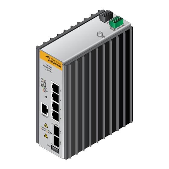
Chapter 1: Overview Front Panels Figure 1 shows the front panel of the AT-IE200-6GT model. The AT-IE200-6FT model is functionally equivalent, but includes 10/100Base-T twisted pair ports. Figure 1: Front panel of the AT-IE200-6GT switch. AT-IE200 Series Installation Guide... -
Page 18: Figure 2: Front Panel Of The At-Ie200-6Gp Switch
Chapter 1: Overview Figure 2 shows the front panel of the AT-IE200-6GP model. The AT-IE200-6FP model is functionally equivalent, but includes 10/100Base-T twisted pair ports. Figure 2: Front panel of the AT-IE200-6GP switch. AT-IE200 Series Installation Guide... -
Page 19: Top Panels
Top Panels Figure 3 shows the top panel of the AT-IE200-6GT and AT-IE200-6FT models. Figure 4 shows the top panel of the AT-IE200-6GP and AT-IE200-6FP models. Figure 3: Top panel of the AT-IE200-6GT and AT-IE200-6FT switches. AT-IE200 Series Installation Guide... -
Page 20: Figure 4: Top Panel Of The At-Ie200-6Gp And At-Ie200-6Fp Switches
Chapter 1: Overview Figure 4: Top panel of the AT-IE200-6GP and AT-IE200-6FP switches. AT-IE200 Series Installation Guide... -
Page 21: 10/100Base-T Twisted Pair Ports
(IEEE 802.3ab-compliant). This feature enables the switch to negotiate with network devices to establish the proper settings, so that the ports on the devices are using different wiring configurations. Maximum Distance The ports have a maximum operating distance of 100 meters (328 feet). AT-IE200 Series Installation Guide... -
Page 22: Power Over Ethernet
100 ohm impedance and a frequency of 100 MHz. Standard TIA/EIA 568-B-compliant Category 6 or 6a shielded cabling. Port Pinouts Refer to Table 17 on page 69 for the port pinouts of the 10/100Base-T twisted pair ports. AT-IE200 Series Installation Guide... -
Page 23: 10/100/1000Base-T Twisted Pair Ports
(IEEE 802.3ab-compliant). This feature enables the switch to automatically negotiate with network devices to establish the proper settings. The MDI and MDI-X settings do not apply when the ports are operating at 1000 Mbps. AT-IE200 Series Installation Guide... -
Page 24: Maximum Distance
100 ohm impedance and a frequency of 100 MHz. Standard TIA/EIA 568-B-compliant Category 6 or 6a shielded cabling. Port Pinouts Refer to Table 18 on page 69 for the port pinouts of the 10/100/1000Base-T twisted pair ports. AT-IE200 Series Installation Guide... -
Page 25: Sfp Slots
The switches support a variety of short and long distance, 100 and 1000 Mbps fiber optic SFP modules. For a list of supported SFP modules, contact your Allied Telesis representative or visit our web site. AT-IE200 Series Installation Guide... -
Page 26: Power Over Ethernet
The switches support all five classes. Table 3: IEEE Powered Device Classes Maximum Power Output Class PD Power Range from a Switch Port 15.4W 0.44W to 12.95W 4.0W 0.44W to 3.84W 7.0W 3.84W to 6.49W AT-IE200 Series Installation Guide... -
Page 27: Power Budget
The High level is the second highest level. Ports set to this level receive power only if all the ports set to the AT-IE200 Series Installation Guide... -
Page 28: Wiring Implementation
Powered devices that comply with the IEEE 802.3at standard are required to support both power delivery methods. Legacy devices that do not comply with the standard will work with the switch if they are powered on pins 1, 2, 3, and 6. AT-IE200 Series Installation Guide... -
Page 29: Alarms
Connect the RELAY_OUT_RTN pin, connector pin 3, to the negative side of the alarm load. Connect the RELAY_OUT pin, connector pin 4, to the positive side of the alarm load. AT-IE200 Series Installation Guide... -
Page 30: Leds
The switch is not receiving power on the PWR 2 input or the input power is operating outside the normal range. Solid green The switch is receiving DC power from the PWR 2 input and is operating normally. AT-IE200 Series Installation Guide... -
Page 31: Twisted Pair Port Leds
LEDs are turned off. To turn on the LEDs, use the NO ECOFRIENDLY LED command. Solid green The port is operating in full duplex mode. Solid amber The port is operating in half duplex mode. AT-IE200 Series Installation Guide... -
Page 32: Figure 7: Port Leds On The At-Ie200-6Fp And At-Ie200-6Gp Switches
The port is transmitting or receiving data at 10 Mbps (AT-IE200-6FT) or 10/100 Mbps (AT- IE200-6GT). Figure 7 shows the port LEDs on the AT-IE200-6GP and AT-IE200-6FP models. Figure 7: Port LEDs on the AT-IE200-6FP and AT-IE200-6GP switches. AT-IE200 Series Installation Guide... -
Page 33: Sfp Leds
Mbps (AT-IE200-6FP) or 10/100 Mbps (AT- IE200-6GP). SFP LEDs The SFP LEDs are located to the right of the slots. Each slot has one LED that indicates the speed and link/ activity status of the SFP. AT-IE200 Series Installation Guide... -
Page 34: Figure 8: Sfp Link/Activity Leds
Solid amber The SFP has established a link to a network device at 100 Mbps, but is not transmitting or receiving network packets. Flashing amber The SFP transceiver is transmitting or receiving network packets at 100 Mbps. AT-IE200 Series Installation Guide... -
Page 35: Console Port
Default baud rate: 9600 bps (range is 9600 to 115200 bps) Data bits: 8 Parity: None Stop bits: 1 Flow control: None Note These settings are for a DEC VT100 or ANSI terminal, or an equivalent terminal emulation program. AT-IE200 Series Installation Guide... -
Page 36: Power Supplies
155W over the operating temperature range. Refer to Appendix A, “Technical Specifications” on page 66 for the input voltage range. Warning Power connector is used as a disconnection device. To de-energize equipment, unplug the power connector from the unit. AT-IE200 Series Installation Guide... -
Page 37: Chapter 2: Beginning The Installation
This chapter contains the safety precautions and guidelines for selecting a site for the switch. The chapter contains the following sections: “Reviewing Safety Precautions” on page 38 “Selecting a Site for the Switch” on page 41 “Unpacking the Switch” on page 42 AT-IE200 Series Installation Guide... -
Page 38: Reviewing Safety Precautions
Review the following safety precautions before you install the switch. Note indicates that a translation of the safety statement is available in a PDF document titled “Translated Safety Statements” (613-000405) on the Allied Telesis website at http://www.alliedtelesis.com. Warning Class 1 Laser product. - Page 39 Circuit Overloading: Consideration should be given to the connection of the equipment to the supply circuit and the effect that overloading of circuits might have on over current protection and supply wiring. Appropriate consideration of equipment nameplate ratings should be used when addressing this concern. AT-IE200 Series Installation Guide...
- Page 40 This equipment meets EN61000-4-5 Class 3 on the DC input and Class 2 on the ETHERNET I/O lines. Warning Allied Telesis does not warrant against lightening or power surges causing damage to the device. Such damage will be the responsibility of the equipment owner.
-
Page 41: Selecting A Site For The Switch
Do not place objects on top of the switch. Do not expose the switch to moisture or water. You should use dedicated power circuits or power conditioners to supply reliable electrical power to the network devices. AT-IE200 Series Installation Guide... -
Page 42: Unpacking The Switch
Chapter 2: Beginning the Installation Unpacking the Switch The following items come with the switch. If any item is missing or damaged, contact your Allied Telesis sales representative for assistance. Note Retain the original packaging material in the event you need to return the unit to Allied Telesis. -
Page 43: Chapter 3: Installing The Switch On A Din Rail Or Wall Mount
Installing the Switch on a DIN Rail or Wall Mount This chapter contains the following sections: “Installing the Switch on a DIN Rail” on page 44 “Installing the Switch on a Wall Mount” on page 46 AT-IE200 Series Installation Guide... -
Page 44: Installing The Switch On A Din Rail
To install the switch on the DIN rail, hook the switch’s mounting bracket onto the DIN rail and rotate the switch down to snap it into place. Figure 9: Attaching the switch to a DIN rail. AT-IE200 Series Installation Guide... - Page 45 Chapter 3: Installing the Switch on a DIN Rail or Wall Mount After snapping the switch onto the DIN rail, go to Chapter 4, “Cabling the Networking Ports” on page 48 to connect the network cables to the ports on the switch. AT-IE200 Series Installation Guide...
-
Page 46: Installing The Switch On A Wall Mount
Figure 10: Attaching the wall mount brackets. 3. Fasten the switch to the wall with #8 x 1.5” pan head wood screws. The distance between the mounting holes is 175 mm. (6.9 in.), as shown in Figure 11. AT-IE200 Series Installation Guide... -
Page 47: Figure 11: Spacing Between Mounting Holes
Chapter 3: Installing the Switch on a DIN Rail or Wall Mount Figure 11: Spacing between mounting holes. AT-IE200 Series Installation Guide... -
Page 48: Chapter 4: Cabling The Networking Ports
Chapter 4 Cabling the Networking Ports This chapter contains the following sections: “Cabling the Twisted Pair Ports” on page 49 “Installing SFP Transceivers” on page 51 AT-IE200 Series Installation Guide... -
Page 49: Cabling The Twisted Pair Ports
Auto-Negotiation, which can result in a mismatch if the end node is operating at a fixed duplex mode of full-duplex. If the Ethernet cables will be connected to equipment that is located outdoors, such as a AT-IE200 Series Installation Guide... - Page 50 CCTV mounted on a pole, the cables will be subjected to surge from lightning or power cross events. A properly rated primary protection device must be installed on the cable prior to connection to the switch. AT-IE200 Series Installation Guide...
-
Page 51: Installing Sfp Transceivers
General guidelines for installing SFP transceivers are: SFP transceivers are hot-swappable. You may install them while the switch is powered Your Allied Telesis sales representative can provide you with a list of supported transceivers for the units. The operational specifications and fiber optic cable requirements of the transceivers are ... -
Page 52: Figure 13: Installing An Sfp Transceiver
2. Remove the transceiver from its shipping container and store the packaging material in a safe location. 3. Position the transceiver with the Allied Telesis label facing to the right. 4. Slide the transceiver into the slot until it clicks into place. -
Page 53: Figure 14: Removing The Dust Cover From An Sfp Transceiver
6. Verify that the handle of the transceiver is in the right-hand position. 7. Connect the fiber optic cable to the transceiver. The connector on the cable should fit snugly into the port and the tab should lock the connector into place. AT-IE200 Series Installation Guide... -
Page 54: Figure 15: Connecting A Fiber Optic Cable To An Sfp Transceiver
Chapter 4: Cabling the Networking Ports Figure 15: Connecting a fiber optic cable to an SFP transceiver. Repeat the procedure to install a second SFP transceiver. AT-IE200 Series Installation Guide... -
Page 55: Chapter 5: Powering On The Switch
“Monitoring the Initialization Processes” on page 58 “Starting a Management Session” on page 59 “Starting a Local Management Session” on page 61 “Specifying Ports in the Command Line Interface” on page 62 AT-IE200 Series Installation Guide... -
Page 56: Connecting The Power
Use two separate conductors of 18 AWG twisted pair properly rated cable to wire the DC power supply to the switch. Stranded cable is recommended. To wire the power, insert the cable into the terminal block and fasten it securely. AT-IE200 Series Installation Guide... -
Page 57: Connecting The Ground Wiring
Keep the wire length as short as possible. Continuity from the grounding screw to the earth ground rod must be less than 0.05 ohms. If a terminal is used, it should be double crimped. AT-IE200 Series Installation Guide... -
Page 58: Monitoring The Initialization Processes
You can monitor the bootup sequence by connecting a terminal or computer that has a terminal emulator program to the console port on the switch. After the switch has initialized its management software, go to “Starting a Management Session” on page 59. AT-IE200 Series Installation Guide... -
Page 59: Starting A Management Session
The security of the switch may be jeopardized if an intruder captures the packet containing your username and password. For secure remote management, see “Secure Shell Management” on page 60. AT-IE200 Series Installation Guide... -
Page 60: Secure Shell Management
Refer to the Software Reference for AT-IE200 Switches for instructions on how to configure the switch for secure HTTPS web browser management. SNMP Refer to the Software Reference for AT-IE200 Switches for instructions on how to configure the switch for SNMP management. The switch does not have any default SNMP community strings. AT-IE200 Series Installation Guide... -
Page 61: Starting A Local Management Session
“manager” as the user name “friend” as the password. The user name and password are case sensitive. The local management session starts when the AlliedWare Plus™ command line prompt is displayed. For information on the command line interface, refer to the Software Reference for AT-IE200 Switches. AT-IE200 Series Installation Guide... -
Page 62: Specifying Ports In The Command Line Interface
Note that you must include the prefix “port1.0.” in the last number of a range. For instructions on the command line interface and the PORT parameter, refer to the Software Reference for AT-IE200 Switches. AT-IE200 Series Installation Guide... -
Page 63: Chapter 6: Troubleshooting
Troubleshooting This chapter contains information on how to troubleshoot the switch if a problem occurs. Note For further assistance, please contact Allied Telesis Technical Support at www.alliedtelesis.com/ support. Problem: The PWR1 and PWR2 LEDs on the front of the switch are off. - Page 64 Connect another network device with a different cable to the port. If the Link LED remains steady on, then the problem is with the original cable or the network device. If the problem is with an SFP transceiver, check that the transceiver is fully inserted in the slot. AT-IE200 Series Installation Guide...
- Page 65 Use the management software on the switch to determine whether the PoE power setting for the port has been reduced to a value below the power requirements of the device. Try connecting the device to a different port on the switch. AT-IE200 Series Installation Guide...
-
Page 66: Appendix A: Technical Specifications
Table 10: Ventilation Requirements for Cabinet Installation Minimum open space 10.2 cm. (4 in.) below Minimum open space 20.3 cm. (8 in.) above Minimum open space 10.2 cm. (4 in.) in front Minimum open space 2.5 cm. (1 in.) on sides AT-IE200 Series Installation Guide... -
Page 67: Environmental Specifications
If the switch is installed in an outdoor cabinet that is directly ventilated to outdoor air, the conformally coated model should be used. Power Specifications Maximum Power Consumptions Table 14: Maximum Power Consumptions AT-IE200-6GT 32 watts AT-IE200-6FT AT-IE200-6GP 155 watts AT-IE200-6FP AT-IE200 Series Installation Guide... -
Page 68: Certifications
EN61000-4-6:2009 EN61000-4-8:2010 EN61000-4-11:2004 Electrical and Laser Safety UL/E/IEC60950-1 CSA 22.2:60950-1 2006/95/EC Low Voltage Directive All Allied Telesis approved SFP EN60825-1 modules EN60825-2 EN/IEC/UL60950-1 FCC CDRH registered RJ-45 Twisted Pair Port Pinouts Figure 16 illustrates the pin layout of the RJ-45 connectors and ports. -
Page 69: Rj-45 Style Serial Console Port Pinouts
Pair 2 + Pair 3 + Pair 3 - Pair 2 - Pair 4 + Pair 4 - RJ-45 Style Serial Console Port Pinouts Table 19 lists the pin signals of the RJ-45 style serial console port. AT-IE200 Series Installation Guide... -
Page 70: Table 19: Rj-45 Style Serial Console Port Pin Signals
Appendix A: Technical Specifications Table 19: RJ-45 Style Serial Console Port Pin Signals Signal Open Looped to pin 7 Transmit Data Ground Ground Receive Data Looped to pin 2 Open AT-IE200 Series Installation Guide...
Need help?
Do you have a question about the IE200 Series and is the answer not in the manual?
Questions and answers