Table of Contents
Advertisement
Quick Links
Download this manual
See also:
Manual
Advertisement
Table of Contents

Related Manuals for Allied Telesis AT-IX5-28GPX


Summary of Contents for Allied Telesis AT-IX5-28GPX
-
Page 1: Installation Guide
AT-IX5-28GPX Gigabit Ethernet Switch SFP+ S1/27 CONSOLE S2/28 1000 LINK 10/100 LINK 2661 Installation Guide C613-04067-00 REV B... - Page 2 Allied Telesis, Inc. has been advised of, known, or should have known, the...
-
Page 3: Electrical Safety And Emissions Standards
Electrical Safety and Emissions Standards This product meets the following standards. U.S. Federal Communications Commission Radiated Energy Note: This equipment has been tested and found to comply with the limits for a Class A digital device pursuant to Part 15 of FCC Rules. -
Page 4: Translated Safety Statements
Translated Safety Statements Important: Safety statements that have the symbol are translated into multiple languages in the Translated Safety Messages document at alliedtelesis.com/support/documentation. -
Page 5: Table Of Contents
Contents Preface ....................................11 Document Conventions ................................12 Contacting Allied Telesis ..............................13 Chapter 1: Overview ................................15 Features ....................................16 10/100/1000 Mbps Twisted Pair Ports ..........................16 Power Over Ethernet ..............................16 SFP+ Slots ..................................16 Power Supply Modules..............................17 Stacking Slots................................17 LEDs....................................17 Installation Options ................................17 MAC Address Table ..............................17 Management Software and Interfaces ..........................18... - Page 6 Contents Master and Member Switches ..............................48 Selection of the Master Switch ............................48 ID Numbers ...................................49 Specifying Ports in the Command Line Interface........................50 Chapter 3: Beginning the Installation ..........................51 Reviewing Safety Precautions ..............................52 Choosing a Site for the Switches ............................56 Planning a Stack ...................................57 Unpacking the Switch ................................59 Chapter 4: Installing the Switch and its Power Supplies ....................61 Installing the Power Cord Retaining Clip ..........................62...
- Page 7 Figures Figure 1: Front Panel of the AT-IX5-28GPX Switch ......................19 Figure 2: Back Panel of the Switch............................19 Figure 3: AT-IX5-28GPX Management Panel ........................20 Figure 4: LEDs for the 10/100/1000Base-T Ports.........................31 Figure 5: SFP+ Slot LEDs ..............................32 Figure 6: Switch ID LED ...............................34 Figure 7: Switch ID LED ...............................34...
- Page 8 Figures Figure 50: Removing the Dust Plug from the S1 Slot ......................92 Figure 51: Removing the Dust Cover from the AT-StackXS/1.0 Transceiver ...............93 Figure 52: Installing the AT-StackXS/1.0 Transceiver in Slot S1..................94 Figure 53: Removing the Dust Plug from the S2 Slot ......................95 Figure 54: Installing the AT-StackXS/1.0 Transceiver in Slot S2..................96 Figure 55: Handle on the AT-StackOP/0.3 and AT-StackOP/9.0 Transceivers..............97 Figure 56: Installing the AT-StackOP/0.3 or AT-StackOP/9.0 Transceiver................98...
- Page 9 Tables Table 1: IEEE Powered Device Classes ..........................24 Table 2: Twisted Pair Cable Requirements for the 10/100Base-TX Ports at 10 or 100Mbps ..........24 Table 3: Twisted Pair Cable Requirements for the 10/100/1000Base-T Ports at 1000Mbps ..........25 Table 4: LEDs on the 10/100/1000Base-T Ports .........................31 Table 5: SFP+ Slot LEDs ..............................33 Table 6: Stacking Slot LEDs ..............................33 Table 7: Stacking Transceivers ............................42...
- Page 10 Tables...
-
Page 11: Preface
Gigabit Ethernet switch. This preface contains the following sections: “Document Conventions” on page 12 “Contacting Allied Telesis” on page 13 Note You can install AT-IX5-28GPX switches as stand-alone devices or in ™ a stack configuration with Virtual Chassis Stacking (VCStack This guide explains both options. -
Page 12: Document Conventions
Preface Document Conventions This document uses the following conventions: Note Notes provide additional information. Caution Cautions inform you that performing or omitting a specific action may result in equipment damage or loss of data. Warning Warnings inform you that performing or omitting a specific action may result in bodily injury. -
Page 13: Contacting Allied Telesis
IX5-28GPX Installation Guide Contacting Allied Telesis If you need assistance with this product, you may contact Allied Telesis technical support by going to the Support & Services section of the Allied Telesis web site at www.alliedtelesis.com/support. You can find links for the following services on this page: 24/7 Online Support —... - Page 14 Preface...
-
Page 15: Chapter 1: Overview
“LEDs” on page 31 “USB Port” on page 36 “Console Port” on page 37 “Power Supplies” on page 38 Note You can install AT-IX5-28GPX switches as stand-alone devices or in a stack configuration with Virtual Chassis Stacking (VCStack). This guide explains both options. -
Page 16: Features
Chapter 1: Overview Features Here are the features of the AT-IX5-28GPX switch: 10/100/1000 Here are the basic features of the 10/100/1000 Mbps twisted pair ports: Mbps Twisted 24 ports per switch Pair Ports 10Base-T, 100Base-TX, and 1000Base-T compliant IEEE 802.3u Auto-Negotiation compliant... -
Page 17: Power Supply Modules
Two SFP+ slots can be used with special stacking transceivers to create a VCStack of up to four switches that operate as a virtual switch. Here are the basic features of the stacking slots on the AT-IX5-28GPX switch: Two stacking ports per switch... -
Page 18: Management Software And Interfaces
Chapter 1: Overview Management Here are the management software and interfaces: Software and AlliedWare Plus Management Software Interfaces Command line interface Web browser interface Management Here are the methods for managing the switches: Methods Local management through the Console port Remote Telnet and Secure Shell management Remote HTTP and HTTPS web browser management SNMPv1, v2c, and v3... -
Page 19: Front And Rear Panels
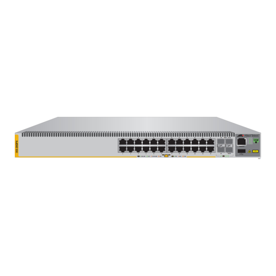
IX5-28GPX Installation Guide Front and Rear Panels The front panel of the AT-IX5-28GPX switch is shown in Figure 1. SFP+ S1/27 CONSOLE S2/28 1000 LINK 10/100 LINK 2661 10/100/1000Base-T Ports Management Panel SFP+ Slots SFP+ or Stacking Slots Figure 1. Front Panel of the AT-IX5-28GPX Switch Figure 2 on page 19 shows the back panel. -
Page 20: Management Panel
Chapter 1: Overview Management Panel Figure 3 identifies the components in the management panel on the AT- IX5-28GPX switch. Console Management Port Switch ID LED eco-friendly Button USB Port Figure 3. AT-IX5-28GPX Management Panel... -
Page 21: 10/100/1000Base-T Twisted Pair Ports
IX5-28GPX Installation Guide 10/100/1000Base-T Twisted Pair Ports The switches have 24 10/100/1000Base-T ports. Speed The ports can operate at 10, 100, or 1000 Mbps. The speeds may be set manually using the management software or automatically with Auto- Negotiation (IEEE 802.3u), the default setting. Note The ports must be set to Auto-Negotiation to function at 1000 Mbps and are not compatible with devices that are not IEEE 802.3u... -
Page 22: Maximum Distance
Chapter 1: Overview The MDI and MDI-X settings do not apply when ports are operating at 1000 Mbps. Maximum The ports have a maximum operating distance of 100 meters (328 feet). Distance Cable For the cable requirements for the ports, refer to Table 2 on page 24. Requirements Port Pinouts Refer to Table 13 on page 125 and Table 14 on page 126 for the port... -
Page 23: Power Over Ethernet
IX5-28GPX Installation Guide Power Over Ethernet The AT-IX5-28GPX switch features Power over Ethernet (PoE) on the 10/ 100/1000Base-T ports. PoE is used to supply power to network devices over the same twisted pair cables that carry the network traffic. The main advantage of PoE is that it can make it easier to install a network. -
Page 24: Powered Device Classes
Chapter 1: Overview Powered Device Powered devices are grouped into the five classes listed in Table 1 on page 24. The classes are based on the amount of power the devices Classes require. The switches support all five classes. Table 1. IEEE Powered Device Classes Maximum Power Output Class PD Power Range... -
Page 25: Power Budget
6a shielded cabling. Power Budget The AT-IX5-28GPX switch has a power budget of 720 watts when two power supply modules are installed. This is the maximum amount of power the switch can provide at one time to the powered devices. -
Page 26: Port Prioritization
Chapter 1: Overview documentation for their power requirements and add the requirements together. The switch should be able to power all of the devices simultaneously as long as the total is below its power budget. If the total exceeds the available power budget, you should consider reducing the number of PoE devices so that all of the devices receive power. -
Page 27: Wiring Implementation
100Base-TX devices that carry the network data. With mode B, the power is provided over the spare wires. The ports on the AT-IX5-28GPX switch deliver the power using pins 1, 2, 3, and 6, which corresponds to mode A in the IEEE 802.3af standard. -
Page 28: Sfp+ Slots
The switches support a variety of short and long distance SFP and SFP+ modules. For a list of supported SFP modules, contact your Allied Telesis representative or visit our web site. Note SFP+ slots 27 and 28 are initially configured as stacking slots for the VCStack feature. -
Page 29: Stacking Sfp+ Slots
IX5-28GPX Installation Guide Stacking SFP+ Slots Two of the four SFP+ slots on the front panel of the switch can be used with stacking transceivers to create a VCStack of up to four AT-IX5- 28GPX switches. The switches of a VCStack act as a single virtual unit. They synchronize their actions so that switching operations, like spanning tree protocols, virtual LANs, and static port trunks, span across all the units and ports. -
Page 30: Eco-Friendly Button
Chapter 1: Overview eco-friendly Button You may turn off the port LEDs to conserve electricity when you are not monitoring the switch. The LEDs are toggled with the eco-friendly button on the front panel of the switch or the ECOFRIENDLY LED and NO ECOFRIENDLY LED commands in the Global Configuration mode of the command line interface. -
Page 31: Leds
IX5-28GPX Installation Guide LEDs Here are descriptions of the LEDs. LEDs for the Each twisted pair port has two LEDs that display link, activity and PoE information. The LEDs are shown in Figure 4. Twisted Pair Ports Link/Activity Link/Activity Figure 4. LEDs for the 10/100/1000Base-T Ports The LEDs are described in Table 4 on page 31. -
Page 32: Leds For The Sfp+ Slots
Chapter 1: Overview Table 4. LEDs on the 10/100/1000Base-T Ports (Continued) State Description Green The switch is detecting a powered device (PD) on the port and is delivering power to it Solid Amber The switch has shutdown PoE+ on the port because of a fault condition. -
Page 33: Leds For The Stacking Slots
IX5-28GPX Installation Guide The LEDs are described in Table 5. Table 5. SFP+ Slot LEDs State Description Link/Activity The slot is empty, the SFP or SFP+ transceiver has not established a link to a network device, or the LEDs are turned off. -
Page 34: Switch Id Led
Chapter 1: Overview Switch ID LED The Switch ID LED, shown in Figure 6 on page 34, displays the ID number of the switch. A stand-alone switch has the ID number 0. Switches in a VCStack have the numbers 1 to 4. Chapter 8, “Powering On the Stack” on page 101 has the procedure for verifying and, if necessary, changing the ID number of the switch. -
Page 35: Figure 8: Switch Id Leds In The Low Power Mode
IX5-28GPX Installation Guide The switch displays the letter “F” for fault on the ID LED if it encounters one of the following problems: A cooling fan has failed. An unsupported power supply module has been installed. One of the power supplies has failed. The internal temperature of the switch has exceeded the normal operating range and the switch may shut down. -
Page 36: Usb Port
Chapter 1: Overview USB Port The management panel has a USB port. You may use the port to store configuration files on flash drives and to restore the files to switches whose settings have been lost or corrupted, or to quickly configure replacement units. -
Page 37: Console Port
IX5-28GPX Installation Guide Console Port The Console port is used to establish a management session with the switch to configure its features and parameter settings. This type of management uses serial RS-232 and is commonly referred to as local or out-of-band management because it is not conducted over your network. -
Page 38: Power Supplies
Chapter 1: Overview Power Supplies The AT-IX5-28GPX switch has two rear slots for hot-swappable power supplies. The switch is supplied with a factory installed blank panel that covers both power supply slots, and with a separate blank panel to use if you only install one power supply. -
Page 39: Chapter 2: Virtual Chassis Stacking
Chapter 2 Virtual Chassis Stacking The sections in this chapter are: “Overview” on page 40 “Stacking Slots” on page 41 “Stacking Transceivers” on page 42 “Stacking Port Topologies” on page 44 “Master and Member Switches” on page 48 “Specifying Ports in the Command Line Interface” on page 50 For more information on the VCStack feature, refer to the Stacking Introduction and Stacking Commands chapters in the Software Reference: AlliedWare Plus Operating System for IX5-28GPX Switches. -
Page 40: Overview
Chapter 2: Virtual Chassis Stacking Overview Virtual Chassis Stacking (VCStack) allows you to connect up to four AT- IX5-28GPX switches to form a virtual switch in which the devices function as a single networking unit. The benefits of VCStack are: Simplifies management - You can manage the devices of the stack as a single unit, rather than individually. -
Page 41: Stacking Slots
IX5-28GPX Installation Guide Stacking Slots The AT-IX5-28GPX switches come with two stacking slots. The slots are the last two SFP+ slots on the switches and are labeled S1/27 and S2/28. The slots have two functions. You may use them with the VCStack feature... -
Page 42: Stacking Transceivers
Chapter 2: Virtual Chassis Stacking Stacking Transceivers You connect the switches of the VCStack with the stacking transceivers listed in Table 7 and shown in Figure 10. Table 7. Stacking Transceivers Stacking Cable Type Operating Distance Transceiver Model AT-StackXS/1.0 Twinax cable 1 meter AT-StackOP/0.3 62.5/125 µm multi-... - Page 43 IX5-28GPX Installation Guide Here are the transceiver guidelines: The stacking transceivers may only be used in the stacking slots and only with the VCStack feature. You may not use the transceivers as regular networking ports. The AT-StackOP/0.3 and AT-StackOP/9.0 transceivers must be connected to other AT-StackOP/0.3 and AT-StackOP/9.0 transceivers.
-
Page 44: Stacking Port Topologies
Chapter 2: Virtual Chassis Stacking Stacking Port Topologies The switches of a stack are connected with the S1 and S2 ports and the stacking transceivers shown in Figure 10 on page 42. There are two wiring configurations. The first topology is called the linear topology. -
Page 45: Figure 12: Stack Of Four Switches In The Linear Topology
IX5-28GPX Installation Guide The stack in Figure 12 on page 45 has four switches in the linear topology. SFP+ S1/27 CONSOLE S2/28 SFP+ S1/27 CONSOLE S2/28 SFP+ S1/27 CONSOLE S2/28 SFP+ S1/27 CONSOLE S2/28 2695 Figure 12. Stack of Four Switches in the Linear Topology The second topology is called the ring topology. -
Page 46: Figure 13: Stack Of Two Switches In The Ring Topology
Chapter 2: Virtual Chassis Stacking SFP+ S1/27 CONSOLE S2/28 SFP+ S1/27 CONSOLE S2/28 2696 Figure 13. Stack of Two Switches in the Ring Topology Figure 14 on page 47 is an example of a stack of four switches in the ring topology. -
Page 47: Figure 14: Stack Of Four Switches In The Ring Topology
IX5-28GPX Installation Guide SFP+ S1/27 CONSOLE S2/28 SFP+ S1/27 CONSOLE S2/28 SFP+ S1/27 CONSOLE S2/28 SFP+ S1/27 CONSOLE S2/28 2697 Figure 14. Stack of Four Switches in the Ring Topology The topologies are the same in terms of network speed and performance. However, the ring topology is the recommended wiring configuration because of the secondary path through the stacking ports. -
Page 48: Master And Member Switches
Chapter 2: Virtual Chassis Stacking Master and Member Switches The stack has one master switch. The functions of the master switch include: Coordinating and monitoring stack operations. Verifying that the switches are using the same version of management software. It automatically downloads its management software over the stacking cables to switches with different software versions. -
Page 49: Id Numbers
IX5-28GPX Installation Guide ID Numbers Each switch must be assigned an ID number. The range is 1 to 4 and the default is 1. The ID numbers are displayed on the ID LEDs on the front panels of the units. You may assign the numbers yourself or you can let the master switch assign the numbers automatically, as explained in Chapter 8, “Powering On the Stack”... -
Page 50: Specifying Ports In The Command Line Interface
Chapter 2: Virtual Chassis Stacking Specifying Ports in the Command Line Interface The command line interface in the management software on the switch has a parameter that you use to specify the individual ports. The parameter is the PORT parameter and Figure 15 shows its format. port1 Stack ID Module ID... -
Page 51: Chapter 3: Beginning The Installation
Chapter 3 Beginning the Installation The chapter contains the following sections: “Reviewing Safety Precautions” on page 52 “Choosing a Site for the Switches” on page 56 “Planning a Stack” on page 57 “Unpacking the Switch” on page 59... -
Page 52: Reviewing Safety Precautions
Chapter 3: Beginning the Installation Reviewing Safety Precautions Please review the following safety precautions before beginning the installation procedure. Note Safety statements that have the symbol are translated into multiple languages in the Translated Safety Messages document at www.alliedtelesis.com/support/documentation. Warning Class 1 Laser product. - Page 53 x510 Series Installation Guide for Virtual Chassis Stacking Warning For AC PSUs, power cord is used as a disconnection device. To de- energize equipment, disconnect the power cord. Warning Class I Equipment. This equipment must be earthed. The power plug must be connected to a properly wired earth ground socket outlet.
- Page 54 Chapter 3: Beginning the Installation Caution Risk of explosion if battery is replaced by an incorrect type. Replace only with the same or equivalent type recommended by the manufacturer. Dispose of used batteries according to the manufacturer’s instructions. Attention: Le remplacement de la batterie par une batterie de type incorrect peut provoquer un danger d’explosion.
- Page 55 x510 Series Installation Guide for Virtual Chassis Stacking Warning Reliable earthing of rack-mounted equipment should be maintained. Particular attention should be given to supply connections other than direct connections to the branch circuits (e.g., use of power strips). Warning To reduce the risk of electric shock, the PoE ports on this product must not connect to cabling that is routed outside the building where this device is located.
-
Page 56: Choosing A Site For The Switches
Chapter 3: Beginning the Installation Choosing a Site for the Switches Observe these requirements when planning the installation of the switches of a stack. If you plan to install the switches in an equipment rack, check to be sure that the rack is safely secured so that it will not tip over. Devices in a rack should be installed starting at the bottom, with the heavier devices near the bottom of the rack. -
Page 57: Planning A Stack
Series Installation Guide for Virtual Chassis Stacking Planning a Stack Here are the guidelines to planning a stack: A stack can have up to four AT-IX5-28GPX switches. Any of the switches in the stack can be the master switch. Switches connected with AT-StackXS/1.0 stacking cables should be installed in a standard 19-inch equipment rack and not more than one meter apart, the length of the stacking cable. -
Page 58: Table 8: Operating Distances Of The At-Stackop/0.3 Transceiver
Chapter 3: Beginning the Installation Table 8. Operating Distances of the AT-StackOP/0.3 Transceiver Minimum Modal Fiber Type Bandwidth @ 850 Operating Range nm (MHz*km) 62.5/125 µm multi- 2 to 26 meters mode fiber optic (7 to 85 feet) cable 2 to 33 meters (7 to 108 feet) 50/125 µm multi- 2 to 66 meters... -
Page 59: Unpacking The Switch
Unpacking the Switch Figure 16 lists the items that come with the switch. If any item is missing or damaged, contact your Allied Telesis sales representative for assistance. One 2 m (6.6 ft) local management cable with RJ-45 (8P8C) and DB-9 (D-sub 9-pin) connectors. - Page 60 Chapter 3: Beginning the Installation...
-
Page 61: Chapter 4: Installing The Switch And Its Power Supplies
Chapter 4 Installing the Switch and its Power Supplies The procedures in this chapter are: “Installing the Power Cord Retaining Clip” on page 62 “Installing Power Supply Modules” on page 63 “Installing the Switches on a Table or Desktop” on page 66 “Installing the Switch in an Equipment Rack”... -
Page 62: Installing The Power Cord Retaining Clip
Chapter 4: Installing the Switch and its Power Supplies Installing the Power Cord Retaining Clip This section applies to AC power supply modules. Perform the following procedure to install the power cord retaining clip on each power supply module: 1. Locate the power cord retaining clip, shown in Figure 17. Figure 17. -
Page 63: Installing Power Supply Modules
IX5-28GPX Installation Guide Installing Power Supply Modules Overview The AT-IX5-28GPX switch has two rear slots for hot-swappable power supplies. You can install one or two AT-PWR800 power supplies. The switch is supplied with a factory installed blank panel that covers both power supply slots, and with a separate blank panel to use if you only install one power supply. -
Page 64: Figure 20: Installing The At-Pwr800 Power Supply Module
Chapter 4: Installing the Switch and its Power Supplies 3. Align the edges of the power supply module with the guides in the slot and carefully slide the module into the chassis until it is flush with the rear panel of the chassis, as shown below. Light pressure may be needed to seat the module on the connector on the rear panel of the chassis. -
Page 65: Figure 21: Securing The At-Pwr800 Power Supply Module
IX5-28GPX Installation Guide 4. Secure the power supply module to the chassis by tightening the two captive screws with a cross-head screwdriver, as shown below. D C P 1 0 0 - 2 4 0 V F A U L A C ~ 1 2 A M A X... -
Page 66: Installing The Switches On A Table Or Desktop
Chapter 4: Installing the Switch and its Power Supplies Installing the Switches on a Table or Desktop You may install the switches on a table or desktop. Here are the guidelines to selecting a site: The table should be level and stable. The power outlets should be located near the switches and be easily accessible. -
Page 67: Installing The Switch In An Equipment Rack
56. Here is the procedure for installing the switch horizontally or vertically in a 19-inch equipment rack. Caution The chassis may be heavy and awkward to lift. Allied Telesis recommends that you get assistance when mounting the chassis in an equipment rack. -
Page 68: Figure 25: Attaching The Equipment Rack Brackets
Chapter 4: Installing the Switch and its Power Supplies 3. Turn the switch over. 4. Attach the two rack mount brackets to the sides of the switch using the bracket screws included with the unit. Figure 25 on page 68 illustrates the four possible bracket positions. -
Page 69: Figure 26: Mounting The Switch Horizontally In An Equipment Rack
IX5-28GPX Installation Guide 5. While another person holds the switch in the equipment rack, secure it using standard equipment rack screws (not provided), as shown in Figure 26 for horizontal mounting and Figure 27 for vertical mounting. 10 00 10 /10 0 LIN /2 7 /2 8... -
Page 70: Connecting Ac Power To A Power Supply Module
Chapter 4: Installing the Switch and its Power Supplies Connecting AC Power to a Power Supply Module To power on a switch with one or two AC Power Supply Modules, perform the following procedure: 1. Position the power cord retaining clip in the up position, as shown in Figure 28. - Page 71 IX5-28GPX Installation Guide 3. Connect the other end of the power cord to an appropriate AC power outlet. For power specifications for the switch, refer to “Power Specifications” on page 124. Warning This unit might have more than one power supply. To reduce the risk of electric shock, disconnect all power cords before servicing the unit.
-
Page 72: Starting A Local Management Session
Chapter 4: Installing the Switch and its Power Supplies Starting a Local Management Session This procedure requires a terminal or a terminal emulator program and the management cable that comes with the switch. To start a local management session on the switch, perform the following procedure: 1. -
Page 73: Monitoring The Initialization Processes
\ \_ __/ /| ______ | | ______ | \ ____ / /______/\____\ \/ /____________/ Allied Telesis Inc. AlliedWare Plus (TM) v5.4.2A Current release filename: x510-5.4.3-3.7.rel Original release filename: x510-5.4.3-3.7.rel Built: 08-Oct-2013 10:43:42 NZDT 2013 by: maker@maker04-build Mounting static filesystems... -
Page 74: Figure 31: Switch Initialization Messages
Chapter 4: Installing the Switch and its Power Supplies Figure 31. Switch Initialization Messages Starting base/loopback... Starting base/poe_done... Starting base/sysctl... Received event poefw.done Starting base/portmapper... Received event syslog.done Starting base/reboot-stability... Starting base/autofs-card... Checking system reboot stability... Starting base/cron... Starting base/appmond... Starting hardware/openhpi... -
Page 75: Figure 33: Switch Initialization Messages (Continued)
IX5-28GPX Installation Guide Assigning Active Workload to HA processes: hsl, nsm, rmond, sflowd, vrrpd, irdpd, lacpd lldpd, loopprotd, mstpd, authd, epsrd, imi, imiproxyd Received event network.activated Loading default configuration Warning: flash:/default.cfg does not exist, loading factory defaults. done! Received event network.configured awplus login: Figure 33. - Page 76 Chapter 4: Installing the Switch and its Power Supplies...
-
Page 77: Chapter 5: Configuring The Switch For Stand-Alone Operations
Chapter 5 Configuring the Switch for Stand-alone Operations Use this chapter if you wish to operate the switch as a single stand-alone switch, instead of stacking it with other switches. This chapter contains the following procedures: “Configuring the Switch for Stand-alone Operations” on page 78 “Specifying Ports in the Command Line Interface for Stand-alone Switches”... -
Page 78: Configuring The Switch For Stand-Alone Operations
Chapter 5: Configuring the Switch for Stand-alone Operations Configuring the Switch for Stand-alone Operations Disabling After the switch has initialized its management software, examine the switch ID LED on the front panel and do one of the following: VCStack If the LED is displaying “0,” the installation procedure is complete. The switch is now ready for network operations as a stand-alone unit. -
Page 79: Figure 35: Show Stack Command
IX5-28GPX Installation Guide Note The User Exec mode is the first level in the command mode interface. For complete information on the modes and commands, refer to the Software Reference: AlliedWare Plus Operating System for IX5-28GPX Switches. 3. Enter the SHOW STACK command to display the status of the VCStack feature. -
Page 80: Figure 37: Confirmation Prompt For The No Stack Enable Command
Chapter 5: Configuring the Switch for Stand-alone Operations The ID parameter is the ID number of the switch, displayed on the ID LED. Replace the parameter with whatever number is on the ID LED. For example, if the ID number of the switch is 1, the default value, enter the command as follows: awplus(config)# no stack 1 enable This confirmation prompt in Figure 37 is displayed. -
Page 81: Confirming The Status Of The Vcstack Feature
IX5-28GPX Installation Guide Confirming the Another way to confirm that VCStack is disabled on the switch is by displaying the status of the last two SFP+ slots on the switch. These are Status of the slots 27 and 28. If VCStack is disabled, you should be able to display the VCStack Feature status of the slots even when they do not have transceivers. -
Page 82: Figure 41: Status Of A Stacking Slot When Vcstack Is Enabled
Chapter 5: Configuring the Switch for Stand-alone Operations The switch displays the message in Figure 41 on page 82 if VCStack is not disabled, in which case you need to disable it by performing the commands in “Disabling VCStack” on page 78. awplus# show interface port1.0.51 %Can’t find interface port1.0.51 awplus#... -
Page 83: Specifying Ports In The Command Line Interface For Stand-Alone Switches
IX5-28GPX Installation Guide Specifying Ports in the Command Line Interface for Stand-alone Switches The command line interface in the management software on the switch has a parameter that you use to specify the individual ports. The parameter is the PORT parameter and Figure 42 shows its format. port1 Stack ID Module ID... - Page 84 Chapter 5: Configuring the Switch for Stand-alone Operations...
-
Page 85: Chapter 6: Verifying The Status Of Vcstack And Activating Vcstack
Chapter 6 Verifying the Status of VCStack and Activating VCStack The procedures in this chapter are: “Verifying the Status of VCStack” on page 86 “Activating the VCStack Feature” on page 87... -
Page 86: Verifying The Status Of Vcstack
Chapter 6: Verifying the Status of VCStack and Activating VCStack Verifying the Status of VCStack Before you install the stacking transceivers to build the stack, you should first test the switches to determine whether the VCStack feature is enabled or disabled, and enable it on any units where it is disabled. On new switches, the feature should be activated because that is the default setting. -
Page 87: Activating The Vcstack Feature
IX5-28GPX Installation Guide Activating the VCStack Feature Perform the following procedure to activate the VCStack feature on switches that display the number “0” on their ID LEDs in the previous procedure. The tasks follow on from “Monitoring the Initialization Processes” on page 73. Activating To activate VCStack, perform the following procedure: VCStack... -
Page 88: Figure 45: Moving To The Global Configuration Mode With The Configure Terminal Command
Chapter 6: Verifying the Status of VCStack and Activating VCStack 4. Enter the CONFIGURE TERMINAL command to move to the Global Configuration mode, as shown in Figure 45. awplus# configure terminal Enter configuration commands, one per line. End with CNTL/Z. awplus(config)# Figure 45. -
Page 89: Figure 49: Rebooting The Switch With The Reboot Command
IX5-28GPX Installation Guide 8. Restart the switch with the REBOOT command, as shown in Figure 49. awplus# reboot reboot system? (y/n): awplus# Figure 49. Rebooting the Switch with the REBOOT Command 9. Type “Y” for yes. 10. Wait one minute for the switch to initialize its management software. 11. - Page 90 Chapter 6: Verifying the Status of VCStack and Activating VCStack...
-
Page 91: Chapter 7: Cabling The Stacking Ports
Chapter 7 Cabling the Stacking Ports This chapter contains the following procedures: “Cabling Switches with AT-StackXS/1.0 Transceivers” on page 92 “Cabling Switches with AT-StackOP/0.3 or AT-StackOP/9.0 Transceivers” on page 97... -
Page 92: Cabling Switches With At-Stackxs/1.0 Transceivers
Chapter 7: Cabling the Stacking Ports Cabling Switches with AT-StackXS/1.0 Transceivers To cable the switches of the stack with AT-StackXS/1.0 transceivers, perform the following procedure: Warning A transceiver can be damaged by static electricity. Be sure to observe all standard electrostatic discharge (ESD) precautions, such as wearing an antistatic wrist strap, to avoid damaging the device. -
Page 93: Figure 51: Removing The Dust Cover From The At-Stackxs/1.0 Transceiver
IX5-28GPX Installation Guide 3. Remove the dust cap from one end of the transceiver, as shown in Figure 51 on page 93. Figure 51. Removing the Dust Cover from the AT-StackXS/1.0 Transceiver... -
Page 94: Figure 52: Installing The At-Stackxs/1.0 Transceiver In Slot S1
Chapter 7: Cabling the Stacking Ports 4. Position the transceiver with the release tab on top and slide the transceiver into the slot, as shown in Figure 52 on page 94. / 2 7 / 2 8 2683 Release tab Figure 52. -
Page 95: Figure 53: Removing The Dust Plug From The S2 Slot
IX5-28GPX Installation Guide 5. Remove the dust cover from the S2 slot in the next switch in the stack as shown in Figure 53 on page 95. Note The cable must crossover to different slots on the switches. The stack will not work if you connect two S1 or S2 slots together. / 2 7 / 2 8 2684... -
Page 96: Figure 54: Installing The At-Stackxs/1.0 Transceiver In Slot S2
Chapter 7: Cabling the Stacking Ports 7. Position the transceiver with the release tab on the bottom and slide it into the slot until it clicks into place, as shown in Figure 54 on page 96. / 2 7 / 2 8 2685 Figure 54. -
Page 97: Cabling Switches With At-Stackop/0.3 Or At-Stackop/9.0 Transceivers
IX5-28GPX Installation Guide Cabling Switches with AT-StackOP/0.3 or AT-StackOP/9.0 Transceivers For guidelines to cabling the switches with AT-StackOP/0.3 or AT- StackOP/9.0 fiber optic transceivers, refer to “Planning a Stack” on page 57. To cable switches with fiber optic transceivers, perform the following procedure: 1. -
Page 98: Figure 56: Installing The At-Stackop/0.3 Or At-Stackop/9.0 Transceiver
Chapter 7: Cabling the Stacking Ports 3. Slide the transceiver into the slot until it clicks into place, as shown in Figure 56 on page 98. / 2 7 / 2 8 2687 / 2 7 / 2 8 2688 Figure 56. -
Page 99: Figure 57: Removing The Dust Cover From A Stacking Transceiver
IX5-28GPX Installation Guide 4. Remove the dust cover from the transceiver, as shown in Figure 57 on page 99. / 2 7 / 2 8 2689 Figure 57. Removing the Dust Cover from a Stacking Transceiver 5. Verify the position of the handle on the transceiver. If the transceiver is in the S1 slot, the handle should be in the upright position, as shown in Figure 58. -
Page 100: Figure 59: Connecting The Fiber Optic Cable To The Stacking Transceiver
Chapter 7: Cabling the Stacking Ports 6. Connect the fiber optic cable to the transceiver, as shown in Figure 59 on page 100. The connector on the cable should fit snugly into the port, and the tab should lock the connector into place. / 2 7 / 2 8 2691... -
Page 101: Chapter 8: Powering On The Stack
Chapter 8 Powering On the Stack This chapter contains the following procedures: “Powering On the Switches Individually” on page 102 “Powering On the Switches Simultaneously” on page 104 “Verifying the Stack” on page 106 Perform “Powering On the Switches Individually” on page 102 if you want to control the assignment of the ID numbers to the switches of the stack. -
Page 102: Powering On The Switches Individually
Chapter 8: Powering On the Stack Powering On the Switches Individually This procedure explains how you can control the assignment of the ID numbers of the switches by powering on the units one at a time during the initial power-on sequence. The first switch is assigned ID number 1, the next unit is assigned ID number 2, and so on. - Page 103 IX5-28GPX Installation Guide 4. Wait two minutes for the new switch to join the stack as a member. As the new switch boots up, the first switch, which has the ID number 1 and at this point is the master switch of the stack, notifies the new switch that its current ID number is already being used and that it should change its number to the next available number, which is 2.
-
Page 104: Powering On The Switches Simultaneously
Chapter 8: Powering On the Stack Powering On the Switches Simultaneously If you want the switches of the stack to use their MAC addresses to automatically assign the ID numbers during the initial power on sequence, all you have to do is power them on simultaneously, rather than one at a time as in the previous procedure. - Page 105 IX5-28GPX Installation Guide switches and are retained by the devices even if you reset or power cycle the stack. 3. To continue with the installation, go to “Verifying the Stack” on page 106.
-
Page 106: Verifying The Stack
Chapter 8: Powering On the Stack Verifying the Stack To verify stack operations, perform the following procedure: 1. Establish a local management session on any switch in the stack. For instructions, refer to “Starting a Local Management Session” on page 72. 2. -
Page 107: Setting The Priority Numbers
IX5-28GPX Installation Guide Setting the This procedure is optional. It explains how to configure the priority settings of the switches. Changing the priority settings protects the stack Priority Numbers configuration should you ever power on the stack with a new member switch that has a lower MAC address than an existing master or member switch. -
Page 108: Figure 63: Saving The Priority Values With The Write Command
Chapter 8: Powering On the Stack 4. Enter the WRITE command to save your change in the configuration file. The switch displays the confirmation prompt in Figure 63. awplus# write Building configuration ... [OK] awplus# Figure 63. Saving the Priority Values with the WRITE Command 5. -
Page 109: Chapter 9: Cabling The Networking Ports
Chapter 9 Cabling the Networking Ports This chapter contains the following procedures: “Cabling the Twisted Pair Ports” on page 110 “Installing SFP and SFP+ Transceivers” on page 112... -
Page 110: Cabling The Twisted Pair Ports
Chapter 9: Cabling the Networking Ports Cabling the Twisted Pair Ports Here are the guidelines to cabling the 10/100/1000Base-T twisted pair ports: The cable specifications for the 10/100/1000Base-T twisted pair ports are listed in Table 2 on page 24 and Table 3 on page 25. The connectors on the cables should fit snugly into the ports, and the tabs should lock the connectors into place. - Page 111 IX5-28GPX Installation Guide The default duplex mode setting of Auto-Negotiation is not appropriate for ports connected to network devices that do not support Auto-Negotiation and have a fixed duplex mode. You should disable Auto-Negotiation on those ports and set their duplex modes manually to avoid the possibility of duplex mode mismatches.
-
Page 112: Installing Sfp And Sfp+ Transceivers
SFP and SFP+ transceivers are hot-swappable. You may install them while the chassis is powered on. Your Allied Telesis sales representative can provide you with a list of supported transceivers for the line cards. The operational specifications and fiber optic cable requirements of the transceivers are provided in the documents included with the devices. -
Page 113: Figure 64: Removing The Dust Plug From An Sfp+ Slot
3. If you are installing the transceiver in a top slot, position the transceiver with the Allied Telesis label facing up. If you are installing the transceiver in a bottom slot, position the transceiver with the label... -
Page 114: Figure 65: Installing An Sfp Or Sfp+ Transceiver
Chapter 9: Cabling the Networking Ports 4. Slide the transceiver into the slot until it clicks into place, as shown in Figure 65 on page 114. / 2 7 / 2 8 2676 Figure 65. Installing an SFP or SFP+ Transceiver Note If you are ready to attach the fiber optic cable to the transceiver, continue with the next step. -
Page 115: Figure 67: Positioning The Sfp Or Sfp+ Handle In The Upright Position
IX5-28GPX Installation Guide 6. Verify the position of the handle on the SFP transceiver. If the transceiver is in a top slot, the handle should be in the upright position, as shown in Figure 67 on page 115. If the transceiver is in a bottom slot, the handle should be in the down position. - Page 116 Chapter 9: Cabling the Networking Ports...
-
Page 117: Chapter 10: Troubleshooting
Check whether the switch is powered up, for example by listening for fan operation, checking the port LEDs and/or starting a management session. If it is powered up, then the Switch ID LED may be faulty. Please contact your Allied Telesis sales representative for assistance. Note The switch may be operating in low power mode, which reduces the number of lit LED segments. - Page 118 Chapter 10: Troubleshooting — Try connecting the unit to another power source. — Try a different power cord. — Verify that the voltage from the power source is within the required levels for your region. Problem 2: All the port LEDs are off even though the ports are connected to active network devices.
- Page 119 IX5-28GPX Installation Guide Problem 4: A twisted pair port on the switch is connected to a network device but the port’s LINK/ACT LED is off. Solutions: The port is unable to establish a link to a network device. Try the following: Verify that the port is connected to the correct twisted pair cable.
- Page 120 Chapter 10: Troubleshooting Verify that the correct type of fiber optic cabling is being used. Verify that the port is connected to the correct fiber optic cable. This is to eliminate the possibility that the port is connected to the wrong remote network device.
- Page 121 1, 2, 3, and 6 on the RJ-45 port, the same pins that carry the network traffic. The second mode, Mode B, defines pins 4, 5, 7, and 8 as the power carriers. The AT-IX5-28GPX switch does not support Mode B. Most powered devices are designed to accept power by either mode, but some legacy devices may only support one mode.
- Page 122 Chapter 10: Troubleshooting...
-
Page 123: Appendix A: Technical Specifications
Appendix A Technical Specifications Physical Specifications Table 9. Physical Specifications Dimensions 4.4 cm x 44.0 cm x 48.0 cm (H x W x D) (1.7 in. x 17.3 in. x 18.9 in.) Weight 5.4 kg Recommended Minimum 10 cm (4.0 in) Ventilation on All Sides Environmental Specifications Table 10. -
Page 124: Power Specifications
Appendix A: Technical Specifications Power Specifications Table 11. Power Specifications Maximum Power Consumption 1000W with two AT-PWR800 PSUs Input Voltage: AT-PWR800 PSU 100-240 VAC,10 A maximum, 50/60 Hz per input Certifications Table 12. Product Certifications EMI (Emissions) FCC Class A, EN55022 Class A, EN61000-3-2, EN61000-3-3, VCCI Class A, CISPR Class A, C-TICK, EMC (Immunity) -
Page 125: Rj-45 Twisted Pair Port Pinouts
IX5-28GPX Installation Guide RJ-45 Twisted Pair Port Pinouts Figure 69 illustrates the pin layout of the RJ-45 connectors and ports. Figure 69. RJ-45 Socket Pin Layout (Front View) Table 13 on page 125 lists the pin signals for 10 and 100 Mbps. Table 13. -
Page 126: Table 14: Pin Signals For 1000 Mbps
Appendix A: Technical Specifications Table 14 lists the pin signals when a port operating at 1000 Mbps. Table 14. Pin Signals for 1000 Mbps Pinout Pair Pair 1 + Pair 1 - Pair 2 + Pair 3 + Pair 3 - Pair 2 - Pair 4 + Pair 4 -... -
Page 127: Rj-45 Style Serial Console Port Pinouts
IX5-28GPX Installation Guide RJ-45 Style Serial Console Port Pinouts Table 15 lists the pin signals of the RJ-45 style serial Console port. Table 15. RJ-45 Style Serial Console Port Pin Signals Signal Looped to pin 8. Looped to pin 7. Transmit Data Ground Ground... -
Page 128: Fiber Optic Specifications Of The At-Stackop/0.3 And At-Stackop/9.0 Transceivers
Appendix A: Technical Specifications Fiber Optic Specifications of the AT-StackOP/0.3 and AT-StackOP/9.0 Transceivers Table 16 lists the fiber optic port specifications for the AT-StackOP/0.3 transceiver. Table 16. Fiber Optic Port Specifications for the AT-StackOP/0.3 Module General Maximum Distances 33 m with 62.5/125 µm (core/ cladding) multimode fiber optic cable 300 m with 50/125 µm (core/... -
Page 129: Table 17: Fiber Optic Port Specifications For The At-Stackop/9.0 Transceiver
IX5-28GPX Installation Guide Table 17 lists the fiber optic port specifications for the AT-StackOP/9.0 transceiver. Table 17. Fiber Optic Port Specifications for the AT-StackOP/9.0 Transceiver General Maximum Distances 9 km Fiber Optic Cable 9/125 µm (core/cladding) single- mode fiber optic cable Transmitter Wavelength 1310 nm...
Need help?
Do you have a question about the AT-IX5-28GPX and is the answer not in the manual?
Questions and answers