Table of Contents
Advertisement
Quick Links
Advertisement
Table of Contents

Related Manuals for Allied Telesis AT-IE510-28GSX


Summary of Contents for Allied Telesis AT-IE510-28GSX
- Page 1 AT-IE510-28GSX Industrial Ethernet Switch Installation Guide 613-002101 Rev. C...
- Page 2 Telesis, Inc. be liable for any incidental, special, indirect, or consequential damages whatsoever, including but not limited to lost profits, arising out of or related to this manual or the information contained herein, even if Allied Telesis, Inc. has been...
- Page 3 Electrical Safety and Emissions Standards U.S. Federal Communications Commission Interference Statement This device complies with part 15 of the FCC Rules. Operation is subject to the following two conditions: (1) This device may not cause harmful interference, and (2) this device must accept any interference received, including interference that may cause undesired operation.
- Page 4 European Union Restriction of the Use of Certain Hazardous Substances (RoHS) in Electrical and Electronic Equipment This Allied Telesis RoHS-compliant product conforms to the European Union Restriction of the Use of Certain Hazardous Substances (RoHS) in Electrical and Electronic Equipment. Allied Telesis ensures RoHS conformance by requiring supplier Declarations of Conformity, monitoring incoming materials, and maintaining manufacturing process controls.
- Page 5 AT-IE510-28GSX Installation Guide Translated Safety Statements Important: The indicates that a translation of the safety statement is available in a PDF document titled “Translated Safety Statements” on the Allied Telesis web site at http:// www.alliedtelesis.com/support.
-
Page 7: Table Of Contents
Contents Preface ....................................13 Document Conventions ..............................14 Contacting Allied Telesis ..............................15 Chapter 1: Overview ................................ 17 Feature Overview .................................18 SFP Slots ................................18 SFP+ Slots ................................18 Stacking Slots ...............................18 Alarm Ports ................................18 LEDs ..................................19 Installation Options..............................19 MAC Address Table ..............................19 Management Software and Interfaces ........................19 Management Methods ............................19... - Page 8 Contents Inserting the Rubber Feet ............................59 Chapter 5: Wiring the DC Connectors ........................... 61 Required Materials and Tools............................62 Connecting the Grounding Wire ..........................63 Connecting the 48/60VDC or -48/-60VDC and RETURN Wires.................. 66 Monitoring the Switch Initialization Process......................... 71 Chapter 6: Installing SFP and SFP+ Transceivers ......................
- Page 9 Figures Figure 1: AT-IE510-28GSX Front Panel ..........................20 Figure 2: AT-IE510-28GSX Back Panel ..........................20 Figure 3: AT-IE510-28GSX Management Panel ........................21 Figure 4: SFP Slot LEDs ..............................26 Figure 5: SFP+ Slot LEDs ..............................27 Figure 6: Switch ID LED ...............................28 Figure 7: Switch ID LED ...............................29 Figure 8: Switch ID LEDs in the Low Power Mode .......................30...
- Page 10 Figures Figure 51: Moving to the Global Configuration Mode with the CONFIGURE TERMINAL Command........93 Figure 52: Activating VCStack with the STACK ENABLE Command ...................93 Figure 53: Returning to the Privileged Exec Mode with the EXIT Command ...............94 Figure 54: Saving the Change with the WRITE Command....................94 Figure 55: Rebooting the Switch with the REBOOT Command....................94 Figure 56: Removing the Dust Plug from the S1 Slot ......................96 Figure 57: Removing the Dust Cover from a TwinAx Cable ....................97...
- Page 11 Tables Table 1: SFP Slot LEDs................................26 Table 2: SFP+ Slot LEDs..............................27 Table 3: Stacking Slot LEDs ..............................28 Table 4: Wire Connection Guide............................68 Table 5: Product Dimensions..............................121 Table 6: Product Weights ..............................121 Table 7: Ventilation Requirements............................121 Table 8: Environmental Specifications..........................122 Table 9: Maximum Power Consumption..........................122 Table 10: Input Voltages..............................122 Table 11: Alarm Contact Power Specifications........................122 Table 12: Product Certifications............................123...
- Page 12 Tables...
-
Page 13: Preface
Preface This guide contains the installation instructions for the AT-IE510-28GSX Industrial Ethernet switch. It explains how to install the switch as a stand- alone unit, or multiple switches in a stack configuration with Virtual Chassis Stacking (VCStack™). This preface contains the following sections: ... -
Page 14: Document Conventions
Preface Document Conventions This document uses the following conventions: Note Notes provide additional information. Caution Cautions inform you that performing or omitting a specific action may result in equipment damage or loss of data. Warning Warnings with the high voltage symbol inform you that performing or omitting a specific action may result in bodily injury. -
Page 15: Contacting Allied Telesis
AT-IE510-28GSX Installation Guide Contacting Allied Telesis If you need assistance with this product, you may contact Allied Telesis technical support by going to the Support & Services section of the Allied Telesis web site at www.alliedtelesis.com/support. You can find links for the following services on this page: ... - Page 16 Preface...
- Page 17 “Power Supplies” on page 33 “Specifying Ports in the Command Line Interface” on page 34 Note The AT-IE510-28GSX switch requires AlliedWare Plus™ version 5.4.5 or later. The switch will not function with earlier versions of the management software.
-
Page 18: Chapter 1: Overview
Chapter 1: Overview Feature Overview This section describes the features of the AT-IE510-28GSX switch. SFP Slots The basic features of the SFP slots on the switch are: Supports 100Base-FX and 1000Base-SX/LX SFP transceivers Supports single-port BiDi 1000Base-LX SFP transceivers ... -
Page 19: Leds
AT-IE510-28GSX Installation Guide LEDs The port LEDs are: Link/activity LEDs for SFP and SFP+ slots Stack ID number LED eco-friendly button turns off the LEDs to conserve electricity Installation The installation options for the switch are: Options ... -
Page 20: Front And Back Panels
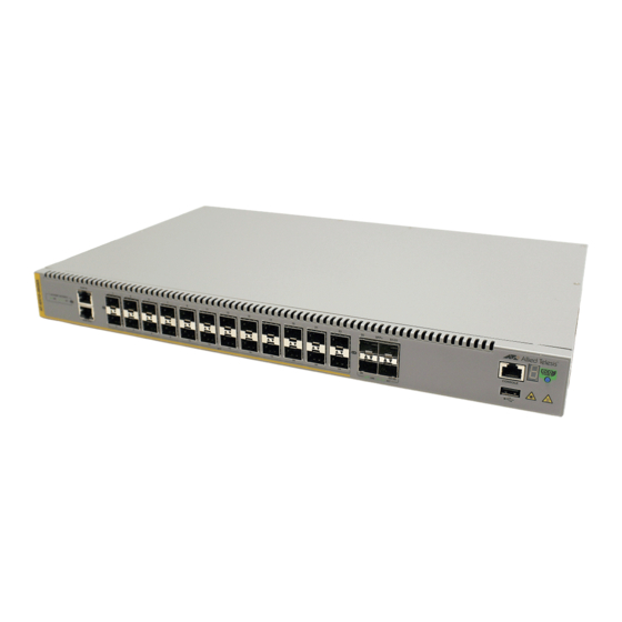
AT-IE510-28GSX SFP Slots Management Panel Alarm Ports SFP+ Slots SFP+ or Stacking Slots Figure 1. AT-IE510-28GSX Front Panel Figure 2 shows the back panel of the switch. Grounding Post DC Power DC Power Connector Connector (Power Supply 2) (Power Supply 1) -
Page 21: Management Panel
AT-IE510-28GSX Installation Guide Management Panel Figure 3 identifies the components in the management panel on the switch. Console Management Port Switch ID LED eco-friendly Button USB Port Figure 3. AT-IE510-28GSX Management Panel... -
Page 22: Sfp+ Slots
The switches support a variety of short and long distance SFP and SFP+ modules. For a list of supported SFP modules, contact your Allied Telesis representative. -
Page 23: Stacking Slots For Vcstack
AT-IE510-28GSX Installation Guide Stacking Slots for VCStack The front panel of the switch contains four SFP+ slots. Slots 27 and 28 can be used to build a VCStack of up to four switches. The switches of a VCStack act as a single virtual unit. They synchronize their actions so that switching operations, like spanning tree protocols, virtual LANs, and static port trunks, span across all the units and ports. -
Page 24: Alarm Ports
Chapter 1: Overview Alarm Ports The switch contains two alarm ports: One for alarm input and one for alarm output. Each alarm port contains three contact points. The alarm ports use RJ-45 connectors. To connect either the alarm input or alarm output, use 24 to 18 AWG cable properly rated for the deployment environment. -
Page 25: Eco-Friendly Button
AT-IE510-28GSX Installation Guide eco-friendly Button You may turn off the port LEDs to conserve electricity when you are not monitoring the switch. The LEDs are toggled with the eco-friendly button on the front panel of the switch or the ECOFRIENDLY LED and NO ECOFRIENDLY LED commands in the Global Configuration mode of the command line interface. -
Page 26: Leds
Chapter 1: Overview LEDs Here are descriptions of the front panel LEDs. SFP Slots LEDs The LEDs for the SFP slots are located between the slots, as shown in Figure 4 on page 26. Each SFP slot has one LED. The left-hand LED is for the top slot and the right-hand LED is for the bottom slot. -
Page 27: Stacking Slots Leds
AT-IE510-28GSX Installation Guide SFP+ Slot LEDs Figure 5. SFP+ Slot LEDs The LEDs are described in Table 2. Table 2. SFP+ Slot LEDs State Description Link/Activity The slot is empty, the SFP or SFP+ transceiver has not established a link to a network device, or the LEDs are turned off. -
Page 28: Switch Id Led
Chapter 1: Overview Table 3. Stacking Slot LEDs State Description Link/Activity The slot is empty, the transceiver has not established a link to a network device, or the LEDs are turned off. To turn on the LEDs, use the eco-friendly button. Solid green The transceiver has established a link at 10 Gbps to another switch in the stack. -
Page 29: Figure 7: Switch Id Led
AT-IE510-28GSX Installation Guide The switch is booting up. The switch has encountered a fault condition. The switch is operating as a stand-alone unit, with the ID number 0. The switch has an ID number of 1 to 4 as part of a VCStack. -
Page 30: Figure 8: Switch Id Leds In The Low Power Mode
Chapter 1: Overview The switch is the master switch of a VCStack. The switch is operating as a stand-alone unit. The switch is a member switch of a VCStack. Figure 8. Switch ID LEDs in the Low Power Mode... -
Page 31: Usb Port
AT-IE510-28GSX Installation Guide USB Port The management panel has a USB port. You may use the port to store configuration files on flash drives and to restore configuration files to switches whose settings have been lost or corrupted, or to quickly configure replacement units. -
Page 32: Console Port
Chapter 1: Overview Console Port The Console port is used to establish a management session with the switch to configure its features and parameter settings. This type of management uses serial RS-232 and is commonly referred to as local or out-of-band management because it is not conducted over your network. -
Page 33: Power Supplies
AT-IE510-28GSX Installation Guide Power Supplies The switch is powered on or off by connecting or disconnecting the power cords. Please review the following information concerning the power supplies: The switch has two pre-installed DC power supplies. The pre-installed DC power supplies have separate connectors on the back panel. -
Page 34: Specifying Ports In The Command Line Interface
The module ID value is used with multi-module products. This value does not apply to the AT-IE510-28GSX switch and should always be 0. The third value is a port number on the switch. You can specify only one... -
Page 35: Chapter 2: Virtual Chassis Stacking
Chapter 2 Virtual Chassis Stacking The sections in this chapter are: “Benefits of VCStack” on page 36 “Stacking Slots” on page 37 “Stacking Port Topologies” on page 38 “Master and Member Switches” on page 42 Note This chapter provides an overview of the Virtual Chassis Stacking (VCStack) feature, which allows you to connect up to four switches to form a virtual switch where the devices function as a single... -
Page 36: Benefits Of Vcstack
Chapter 2: Virtual Chassis Stacking Benefits of VCStack The benefits of the VCStack feature are: Simplifies management - You can manage the devices of the stack as a single unit, rather than individually. Your local and remote management sessions automatically give you management access to all the devices. -
Page 37: Stacking Slots
AT-IE510-28GSX Installation Guide Stacking Slots The switch comes with two stacking slots. The slots are the last two SFP+ slots on the switches and are labeled “S1/27” and “S2/28” on the switch. The slots have two functions. You can use them with the VCStack feature to build a stack of switches, or you can disable the VCStack feature and use them as additional networking slots. -
Page 38: Stacking Port Topologies
Chapter 2: Virtual Chassis Stacking Stacking Port Topologies There are two possible wiring topologies when you use the S1/27 and S2/ 28 slots to build a VCStack. The first topology is called the linear topology. In this topology the switches are connected with a single pathway. A transceiver in one switch is connected to a transceiver in the next switch, which is connected to the next switch, and so on. -
Page 39: Figure 11: Stack Of Four Switches In The Linear Topology
AT-IE510-28GSX Installation Guide Figure 11. Stack of Four Switches in the Linear Topology The second topology is called a ring topology. It is similar to the linear topology, except that the unused stacking ports on the end switches of the stack are connected to form a physical loop. -
Page 40: Figure 12: Stack Of Two Switches In The Ring Topology
Chapter 2: Virtual Chassis Stacking Figure 12. Stack of Two Switches in the Ring Topology Figure 13 is an example of a stack of four switches in the ring topology. -
Page 41: Figure 13: Stack Of Four Switches In The Ring Topology
AT-IE510-28GSX Installation Guide Figure 13. Stack of Four Switches in the Ring Topology The topologies are the same in terms of network speed and performance. However, the ring topology is the recommended wiring configuration because of the secondary path through the stacking ports. The two pathways protect the switches of the stack against the loss of communications due to a failure of a stacking port, cable, or switch. -
Page 42: Master And Member Switches
Chapter 2: Virtual Chassis Stacking Master and Member Switches The stack has one master switch. The functions of the master switch include: Coordinating and monitoring stack operations. Verifying that the switches are using the same version of management software. It automatically downloads its management software over the stacking cables to switches with different software versions. -
Page 43: Id Numbers
AT-IE510-28GSX Installation Guide ID Numbers Each switch must be assigned an ID number. The range is 1 to 4 and the default is 1. The ID numbers are displayed on the ID LEDs on the front panels of the units. You can assign the numbers yourself or you can let the master switch assign the numbers automatically. - Page 44 Chapter 2: Virtual Chassis Stacking...
-
Page 45: Chapter 3: Beginning The Installation
Chapter 3 Beginning the Installation The chapter contains the following sections: “Reviewing Safety Precautions” on page 46 “Choosing a Site for the Switches” on page 50 “Planning a Stack” on page 51 “Unpacking the Switch” on page 52... -
Page 46: Reviewing Safety Precautions
Chapter 3: Beginning the Installation Reviewing Safety Precautions Please review the following safety precautions before beginning the installation procedure. Note Safety statements that have the symbol are translated into multiple languages in the Translated Safety Statements document at www.alliedtelesis.com/support. Warning ... - Page 47 AT-IE510-28GSX Installation Guide Warning Do not work on equipment or cables during periods of lightning activity. Warning This equipment must be earthed. The ground lug on the switch must be connected to a properly earthed bonding point. Note Ground resistance from the building primary bonding point to earth should be less than 25 ohms.
- Page 48 Chapter 3: Beginning the Installation Caution Risk of explosion if battery is replaced by an incorrect type. Replace only with the same or equivalent type recommended by the manufacturer. Dispose of used batteries according to the manufacturer’s instructions. Attention: Le remplacement de la batterie par une batterie de type incorrect peut provoquer un danger d’explosion.
- Page 49 Operating Temperature. This product is designed for a maximum ambient temperature of 75 degrees C. E53 Note Allied Telesis does not warrant against lightening or power surges causing damage to the device. Such damage will be the responsibility of the equipment owner.
-
Page 50: Choosing A Site For The Switches
Chapter 3: Beginning the Installation Choosing a Site for the Switches Observe these requirements when planning a stack installation. If you plan to install the switches in an equipment rack, check to be sure that the rack is safely secured so that it will not tip over. Devices in a rack should be installed starting at the bottom, with the heavier devices near the bottom of the rack. -
Page 51: Planning A Stack
Planning a Stack The guidelines to planning a stack are: A stack can have up to four AT-IE510-28GSX switches. Switches connected with Allied Telesis TwinAx cables should be installed in a 19-inch or 23-inch equipment rack and not be more than the length of the cable apart. -
Page 52: Unpacking The Switch
Unpacking the Switch Figure 14 lists items that come with the switch. If any item is missing or damaged, contact your Allied Telesis sales representative for assistance. One 2 m (6.6 ft) local management cable with RJ-45 (8P8C) and DB-9 (D-sub 9-pin) -
Page 53: Chapter 4: Mounting The Switch
Chapter 4 Mounting the Switch The procedures in this chapter are: “Installing the Switch in an Equipment Rack” on page 54 “Installing the Switch on a Wall Mount” on page 58 “Inserting the Rubber Feet” on page 59... -
Page 54: Installing The Switch In An Equipment Rack
19-inch rack. If you are installing the switch in this configuration, you do not need to move the brackets. Caution The chassis may be heavy and awkward to lift. Allied Telesis recommends that you get assistance when mounting the chassis in an equipment rack. -
Page 55: Figure 15: Attaching The Equipment Rack Brackets For A 19-Inch Rack, Mid Mount (Pre-Installed Bracket Position)
AT-IE510-28GSX Installation Guide Figure 15. Attaching the Equipment Rack Brackets for a 19-Inch Rack, Mid Mount (Pre-installed bracket position) Figure 16. Attaching the Equipment Rack Brackets for a 19-Inch Rack, Front Mount... -
Page 56: Figure 17: Attaching The Equipment Rack Brackets For A 23-Inch Rack, Front Mount
Chapter 4: Mounting the Switch Figure 17. Attaching the Equipment Rack Brackets for a 23-Inch Rack, Front Mount Figure 18. Attaching the Equipment Rack Brackets for a 23-Inch Rack, Mid Mount... -
Page 57: Figure 19: Mounting The Switch In An Equipment Rack
AT-IE510-28GSX Installation Guide 4. While another person holds the switch in the equipment rack, secure it using standard equipment rack screws (not provided), as shown in Figure 19. Figure 19. Mounting the Switch in an Equipment Rack 5. If you are installing a VCStack, repeat this procedure to install the... -
Page 58: Installing The Switch On A Wall Mount
Chapter 4: Mounting the Switch Installing the Switch on a Wall Mount This section contains the procedure for installing the switch on a wall mount The procedure requires the following items: Two wall mount brackets (included with the switch) ... -
Page 59: Inserting The Rubber Feet
AT-IE510-28GSX Installation Guide Inserting the Rubber Feet Four rubber feet are included in the box with the unit. If you need to set the unit on a table or desktop, you should insert the rubber feet first. 1. Place the unit upside down on a level, secure surface. - Page 60 Chapter 4: Mounting the Switch...
-
Page 61: Chapter 5: Wiring The Dc Connectors
Chapter 5 Wiring the DC Connectors This chapter describes how to connect the grounding and power wires to the DC connectors on the back panel of the switch. “Required Materials and Tools” on page 62 “Connecting the Grounding Wire” on page 63 ... -
Page 62: Required Materials And Tools
Chapter 5: Wiring the DC Connectors Required Materials and Tools The procedure requires the following materials: One 12 AWG stranded grounding wire. The standard color for the wire is green with a yellow stripe. One 16 AWG minimum stranded power wire for the 48/60VDC or -48/-60VDC connection. -
Page 63: Connecting The Grounding Wire
AT-IE510-28GSX Installation Guide Connecting the Grounding Wire To connect the grounding wire to the grounding post, perform the following procedure: Warning When installing this equipment, always ensure that the power supply ground connection is installed first and disconnected last. -
Page 64: Figure 25: Removing The Nut From The Grounding Post
4. Attach the grounding lug and wire to the grounding post and secure them with the nut removed in Step 3 and a 7mm wrench. Allied Telesis recommends tightening the nut to 15 in-lbs. Refer to Figure 26. - Page 65 AT-IE510-28GSX Installation Guide 5. Connect the other end of the grounding wire to the building protective earth. 6. After installing the grounding wire, go to “Connecting the 48/60VDC or -48/-60VDC and RETURN Wires” on page 66.
-
Page 66: Connecting The 48/60Vdc Or -48/-60Vdc And Return Wires
Chapter 5: Wiring the DC Connectors Connecting the 48/60VDC or -48/-60VDC and RETURN Wires The switch can use either 48/60VDC or -48/-60VDC. If you use positive voltage, the negative RETURN wires must be tied to earthed ground at the power plant. If you use negative voltage, the positive RETURN wires must be tied to earthed ground at the power plant. -
Page 67: Figure 27: Loosening The Two Captive Screws On The Dc Connector
AT-IE510-28GSX Installation Guide Figure 27. Loosening the Two Captive Screws on the DC Connector 2. Slide the DC connector from the chassis. Refer to Figure 28. Figure 28. Removing the DC Connector 3. Use a 3mm (0.125 in.) flat-head screwdriver to loosen the two captive... -
Page 68: Figure 29: Loosening The Captive Screws On The Dc Connector
5. Insert the black and red wires into the power connector according to Table 4. Secure them by tightening the captive screw with a flat-head screwdriver. Allied Telesis recommends tightening the screw to 5 in- lbs. Refer to Figure 31. -
Page 69: Figure 31: Inserting The Voltage And Return Wires
AT-IE510-28GSX Installation Guide Figure 31. Inserting the Voltage and Return Wires 6. Slide the DC connector into the slot on the switch. Refer to Figure 32. Figure 32. Sliding the DC Connector into the Switch 7. Tighten the two captive screws on the sides of the DC connector to... -
Page 70: Figure 33: Securing The Dc Connector To The Switch
Chapter 5: Wiring the DC Connectors Figure 33. Securing the DC Connector to the Switch Caution Verify that the DC circuit is powered off before connecting the power wires from the switch to the circuit. 8. Connect the voltage and RETURN wires to the DC circuit. 9. -
Page 71: Monitoring The Switch Initialization Process
AT-IE510-28GSX Installation Guide Monitoring the Switch Initialization Process It takes about thirty seconds to initialize the management software. To monitor the initialization process, do one of the following: Watch the switch ID LED. It displays the number “8” for about the first 15 seconds and then the number “1.”... - Page 72 Chapter 5: Wiring the DC Connectors...
-
Page 73: Chapter 6: Installing Sfp And Sfp+ Transceivers
Chapter 6 Installing SFP and SFP+ Transceivers This chapter contains the guidelines and procedures for installing SFP and SFP+ transceivers. “General Guidelines” on page 74 “Installing SFP and SFP+ Modules” on page 75... -
Page 74: General Guidelines
Slots S1/27 and S2/28 support 10GBase transceivers and direct connect TwinAx cables when VCStack is enabled. Your Allied Telesis sales representative can provide you with a list of supported transceivers. For a list of supported types of transceivers, refer to “Feature Overview” on page 18. -
Page 75: Installing Sfp And Sfp+ Modules
3. If you are installing the transceiver in a top slot, position the transceiver with the Allied Telesis label facing up. If you are installing the transceiver in a bottom slot, position the transceiver with the label facing down. -
Page 76: Figure 35: Installing A Transceiver
Chapter 6: Installing SFP and SFP+ Transceivers Figure 35. Installing a Transceiver Note If you are ready to attach the fiber optic cable to the transceiver, continue with the next step. Otherwise, repeat Step 1 through Step 4 to install the remaining transceivers in the switch. 5. -
Page 77: Figure 37: Positioning The Sfp Handle In The Upright Position
AT-IE510-28GSX Installation Guide SFP Handle Figure 37. Positioning the SFP Handle in the Upright Position 7. Connect the fiber optic cable to the transceiver, as shown in Figure 38. The connector on the cable should fit snugly into the port, and the tab should lock the connector into place. - Page 78 Chapter 6: Installing SFP and SFP+ Transceivers...
-
Page 79: Chapter 7: Configuring The Switch For Stand-Alone Operations
Chapter 7 Configuring the Switch for Stand-alone Operations This chapter contains the following procedures: “Determining the Status of the VCStack Feature” on page 80 “Starting a Local Management Session” on page 81 “Disabling VCStack” on page 83 ... -
Page 80: Determining The Status Of The Vcstack Feature
Chapter 7: Configuring the Switch for Stand-alone Operations Determining the Status of the VCStack Feature After the switch has initialized its management software, examine the switch ID LED on the front panel and do one of the following: If the LED is displaying “0,” the VCStack feature is disabled and the switch is ready for network operations as a stand-alone unit. -
Page 81: Starting A Local Management Session
AT-IE510-28GSX Installation Guide Starting a Local Management Session This procedure requires a terminal or a terminal emulator program and the management cable that comes with the switch. To start a local management session on the switch, perform the following procedure: 1. -
Page 82: Figure 40: User Exec Mode Prompt
Figure 40 is displayed. awplus> Figure 40. User Exec Mode Prompt The User Exec mode is the first level in the command mode interface. For complete information on the modes and commands, refer to the AT-IE510-28GSX Command Reference on AlliedTelesis.com. -
Page 83: Disabling Vcstack
AT-IE510-28GSX Installation Guide Disabling VCStack Caution You must reset the switch to disable the VCStack feature. If the switch is already connected to a live network, some network traffic may be lost. To disable the VCStack feature to use the switch as stand-alone unit, perform the following procedure: 1. -
Page 84: Figure 42: Moving To The Global Configuration Mode
Chapter 7: Configuring the Switch for Stand-alone Operations awplus> enable awplus# configure terminal Enter configuration commands, one per line. End with CNTL/Z awplus(config)# Figure 42. Moving to the Global Configuration Mode 5. To. disable the VCStack feature on the switch, enter the NO STACK ENABLE command, which has this format: no stack enable... - Page 85 AT-IE510-28GSX Installation Guide 11. Wait for the switch to initialize its management software and afterwards examine the Switch ID LED. The switch is ready for normal network operations as a stand-alone unit when its ID number is “0.” Refer to see the VCStack Feature Overview and Configuration Guide on AlliedTelesis.com instructions on how to configure the operating...
-
Page 86: Confirming The Status Of The Vcstack Feature
Chapter 7: Configuring the Switch for Stand-alone Operations Confirming the Status of the VCStack Feature Another way to confirm that VCStack is disabled on the switch is by displaying the status of the last two SFP+ slots, slots 27 and 28, on the switch. -
Page 87: Figure 47: Status Of A Stacking Slot When Vcstack Is Enabled
AT-IE510-28GSX Installation Guide awplus# show interface port1.0.27 %Can’t find interface port1.0.27 awplus# Figure 47. Status of a Stacking Slot When VCStack is Enabled Once you have confirmed VCStack is disabled, go to Chapter 6, “Installing SFP and SFP+ Transceivers” on page 73, to continue with the installation. - Page 88 Chapter 7: Configuring the Switch for Stand-alone Operations...
-
Page 89: Chapter 8: Verifying The Status Of Vcstack
Chapter 8 Verifying the Status of VCStack The procedures in this chapter are: “Verifying the Status of VCStack” on page 90 “Starting a Local Management Session” on page 91 “Activating the VCStack Feature” on page 93... -
Page 90: Verifying The Status Of Vcstack
Chapter 8: Verifying the Status of VCStack Verifying the Status of VCStack Before cabling slots S1/27 and S2/28 to build the stack, you should first test the switches to determine whether the VCStack feature is enabled or disabled, and enable it on any units where it is disabled. On new switches, the feature should be activated because that is the default setting. -
Page 91: Starting A Local Management Session
AT-IE510-28GSX Installation Guide Starting a Local Management Session This procedure requires a terminal or a terminal emulator program and the management cable that comes with the switch. To start a local management session on the switch, perform the following procedure: 1. -
Page 92: Figure 49: User Exec Mode Prompt
Figure 49 is displayed. awplus> Figure 49. User Exec Mode Prompt The User Exec mode is the first level in the command mode interface. For complete information on the modes and commands, refer to the AT-IE510-28GSX Command Reference on AlliedTelesis.com. -
Page 93: Activating The Vcstack Feature
AT-IE510-28GSX Installation Guide Activating the VCStack Feature When a switch displays the number “0” in its ID LED you must activate the VCStack feature to install a VCstack. The following procedures assume you have confirmed that the VCStack feature is disabled and that the switch is powered on. -
Page 94: Figure 53: Returning To The Privileged Exec Mode With The Exit Command
Chapter 8: Verifying the Status of VCStack awplus(config)# exit awplus# Figure 53. Returning to the Privileged Exec Mode with the EXIT Command 6. Enter the WRITE command to save your change, as shown in Figure 54. awplus# write Building configuration ... [OK] awplus# Figure 54. -
Page 95: Chapter 9: Cabling The Stacking Ports
Chapter 9 Cabling the Stacking Ports This chapter contains the following procedures: “Cabling Switches with TwinAx Cables” on page 96 “Cabling Switches with SFP+ Modules” on page 101... -
Page 96: Cabling Switches With Twinax Cables
Chapter 9: Cabling the Stacking Ports Cabling Switches with TwinAx Cables You can use any Allied Telesis TwinAx cable to connect the switches in a stack. Allied Telesis provides the following TwinAx cables: AT-SP10TW1—1 meter SFP+ direct attach cable ... -
Page 97: Figure 57: Removing The Dust Cover From A Twinax Cable
AT-IE510-28GSX Installation Guide 2. Remove the cable from its shipping container and store the packaging material in a safe location. 3. Remove the dust cap from one end of the cable, as shown in Figure 57. Figure 57. Removing the Dust Cover from a TwinAx Cable 4. -
Page 98: Figure 58: Installing A Twinax Cable In Slot S1
Chapter 9: Cabling the Stacking Ports Release Figure 58. Installing a TwinAx Cable in Slot S1 5. Remove the dust cover from the S2 slot in the next switch in the stack as shown in Figure 59. Note The cable must cross over to different slots on the switches. The stack will not work if you connect two S1 or S2 slots together. -
Page 99: Figure 59: Removing The Dust Plug From The S2 Slot
AT-IE510-28GSX Installation Guide Figure 59. Removing the Dust Plug from the S2 Slot 6. Remove the dust cover from the connector on the other end of the cable. 7. Position the cable with the release tab on the bottom and slide it into... -
Page 100: Figure 60: Installing A Twinax Cable In Slot S2
Chapter 9: Cabling the Stacking Ports Figure 60. Installing a TwinAx Cable in Slot S2 8. Repeat this procedure to connect additional switches to the stack with TwinAx cables. 9. To create the redundant path with the ring topology shown in Figure 12 on page 40 and Figure 13 on page 41, connect a cable to the empty stacking slots on the top and bottom switches. -
Page 101: Cabling Switches With Sfp+ Modules
AT-IE510-28GSX Installation Guide Cabling Switches with SFP+ Modules You can use any Allied Telesis 10G SFP+ module to connect the switches in a stack. Note You must use a verified Allied Telesis TwinAx cable or SFP+ module to configure switches in a VCStack. Cables and modules from other vendors are not supported and will fail to create an active link. -
Page 102: Figure 62: Installing An Sfp+ Module
Chapter 9: Cabling the Stacking Ports Figure 62. Installing an SFP+ Module 4. Remove the dust cover from the SFP+ module, as shown in Figure 63. Figure 63. Removing the Dust Cover from an SFP+ Module 5. Verify the position of the handle on the SFP+ module. If the module is in the S1 slot, the handle should be in the upright position, as shown in Figure 64. -
Page 103: Figure 64: Positioning The Handle In The Upright Position
AT-IE510-28GSX Installation Guide SFP Handle Figure 64. Positioning the Handle in the Upright Position 6. Connect the fiber optic cable to the SFP+ module, as shown in Figure 65. The connector on the cable should fit snugly into the port, and the tab should lock the connector into place. - Page 104 Chapter 9: Cabling the Stacking Ports 8. Repeat this procedure on the other switches of the stack. The connections must cross over such that an SFP+ module in slot 1 connects to an SFP+ module in slot 2. 9. After you connect the fiber optic cables to all of the switches, go to Chapter 10, “Powering On the Stack”...
-
Page 105: Chapter 10: Powering On The Stack
Otherwise, perform “Powering On the Switches Simultaneously” on page 108 to have the switches assign the numbers automatically. After the ID numbers are assigned, you may change them with the STACK RENUMBER command, described in the AT-IE510-28GSX Command Reference on AlliedTelesis.com. Note You should not change the ID numbers of the switches after you begin to configure the parameter settings. -
Page 106: Powering On The Switches Individually
Chapter 10: Powering On the Stack Powering On the Switches Individually This procedure explains how you can control the assignment of the ID numbers of the switches by powering on the units one at a time during the initial power-on sequence. The first switch is assigned ID number 1, the next unit is assigned ID number 2, and so on. - Page 107 AT-IE510-28GSX Installation Guide Consider the following items as you power on the switch: Connecting the two power cords to power sources that are on different circuits will provide power redundancy to the switch in the event a circuit fails.
-
Page 108: Powering On The Switches Simultaneously
Chapter 10: Powering On the Stack Powering On the Switches Simultaneously If you want the switches of the stack to use their MAC addresses to automatically assign the ID numbers during the initial power-on sequence, all you have to do is power them on simultaneously, rather than one at a time as in the previous procedure. - Page 109 AT-IE510-28GSX Installation Guide specifications of the switches. Warning Power cord is used as a disconnection device. To de-energize equipment, disconnect the power cord. Note Pluggable Equipment. The socket outlet shall be installed near the equipment and shall be easily accessible.
-
Page 110: Verifying The Stack
Chapter 10: Powering On the Stack Verifying the Stack To verify stack operations, perform the following procedure: 1. Establish a local management session on any switch in the stack. For instructions, refer to “Starting a Local Management Session” on page 91. 2. -
Page 111: Setting The Priority Numbers
AT-IE510-28GSX Installation Guide Otherwise, go to Chapter 6, “Installing SFP and SFP+ Transceivers” on page 73, to continue with the installation. Setting the This procedure is optional. It explains how to configure the priority settings of the switches. Changing the priority settings protects the stack... -
Page 112: Figure 68: Returning To The Privileged Exec Mode
Chapter 10: Powering On the Stack awplus(config)# exit awplus# Figure 68. Returning to the Privileged Exec Mode 4. Enter the WRITE command to save your change in the configuration file. The switch displays the confirmation prompt in Figure 69. awplus# write Building configuration ... -
Page 113: Monitoring The Stack Initialization Processes
AT-IE510-28GSX Installation Guide Monitoring the Stack Initialization Processes You can monitor the initialization sequence of the stack by connecting a terminal or computer that has a terminal emulator program to the Console port on any switch in the stack. You will see messages similar to those in Figure 70 here to Figure 72 on page 115. -
Page 114: Figure 71: Switch Initialization Messages (Continued)
Chapter 10: Powering On the Stack Received event poefw.done Starting base/portmapper... Received event syslog.done Starting base/reboot-stability... Starting base/autofs-card... Checking system reboot stability... Starting base/cron... Starting base/appmond... Starting hardware/openhpi... Starting hardware/timeout... Starting base/inet... Starting base/modules... Received event modules.done Received event board.inserted Received event hardware.done Starting network/startup... -
Page 115: Figure 72: Switch Initialization Messages (Continued)
AT-IE510-28GSX Installation Guide Received event network.activated Loading default configuration Warning: flash:/default.cfg does not exist, loading factory defaults. done! Received event network.configured awplus login: 21:12:34 awplus VCS[734]: Duplicate member-ID 1 detected for 0015.774f.ed30 and 0011.2233.4455 21:12:34 awplus VCS[734]: Automatically renumbering member-1 (0015.774f.ed30), selecting unused member-ID... - Page 116 Chapter 10: Powering On the Stack...
-
Page 117: Chapter 11: Troubleshooting
9, “Cabling the Stacking Ports” on page 95. Verify that the transceivers are fully inserted into the S1 and S2 slots. Verify that the TwinAx direct connect cables or SFP+ transceivers in slots S1/27 and S2/28 are from Allied Telesis. The switches will... - Page 118 Chapter 11: Troubleshooting not form the stack if the cables or transceivers are from another vendor. Verify that VCStack is activated on the switches. For instructions, refer to Chapter 8, “Verifying the Status of VCStack” on page 89. It could be that the switches have incompatible versions of the management software.
- Page 119 AT-IE510-28GSX Installation Guide Problem 7: The switch functions intermittently. Solutions: Check the system hardware status through the management software: Use the SHOW SYSTEM ENVIRONMENT command in the Privileged Exec mode to verify that the input voltage from the power source to the switch is stable and within the approved operating range.
- Page 120 Chapter 11: Troubleshooting...
-
Page 121: Appendix A: Technical Specifications
“RJ-45 Style Alarm Port Pinouts” on page 125 Physical Specifications Dimensions (H x W x D) Table 5. Product Dimensions AT-IE510-28GSX 4.4 cm x 44.0 cm x 30.0 cm (1.7 in. x 17.3 in. x 11.8 in.) Weights Table 6. Product Weights AT-IE510-28GSX 4.8 kg (10.6 lb.) -
Page 122: Environmental Specifications
3,000 m (9,842 ft) Maximum Nonoperating Altitude 4,000 m (13,100 ft) Power Specifications Maximum Power Consumption Table 9. Maximum Power Consumption AT-IE510-28GSX 74 watts per input Input Voltages Table 10. Input Voltages AT-IE510-28GSX 36Vdc to 72Vdc or -36Vdc to -72Vdc, 3.0A... -
Page 123: Certifications
AT-IE510-28GSX Installation Guide Certifications Table 12. Product Certifications EMI Emissions FCC Part 15B Class A ICES-003 Class A EN55032:2015 Class A VCCI- Class A EN61000-3-2:2006+A1:2009+A2:2009 EN61000-3-3:2008 EMC Immunity EN55024:2010 EN61000-4-2:2009 EN61000-4-3:2006 + A2:2010 EN61000-4-4:2012 EN61000-4-5:2006 EN61000-4-6:2009 EN61000-4-8:2010 EN61000-4-11:2004 Electrical and Laser Safety UL/E/IEC60950-1 CSA 22.2:60950-1... -
Page 124: Style Serial Console Port Pinouts
Appendix A: Technical Specifications RJ-45 Style Serial Console Port Pinouts Table 13 lists the pin signals of the RJ-45 style serial Console port. Table 13. RJ-45 Style Serial Console Port Pin Signals Signal Looped to pin 8 Looped to pin 7 Transmit Data Ground Ground... -
Page 125: Style Alarm Port Pinouts
AT-IE510-28GSX Installation Guide RJ-45 Style Alarm Port Pinouts Alarm Input Table 14 lists the pin signals of the RJ-45 style alarm input port. Table 14. RJ-45 Style Alarm Input Port Pin Signals Signal Alarm input 1 Alarm input 1 return... - Page 126 Appendix A: Technical Specifications...
Need help?
Do you have a question about the AT-IE510-28GSX and is the answer not in the manual?
Questions and answers