
Related Manuals for Allied Telesis AT-IFS802SP/POE


Summary of Contents for Allied Telesis AT-IFS802SP/POE
- Page 1 AT-IFS802SP/POE 8x10/100TX POE Layer 2 Managed Industrial Switch AT-IFS802SP/POE Installation and User’s Guide 613-001691 Rev.A...
- Page 2 Allied Telesis, Inc. has been advised of, known, or should have known, the...
-
Page 3: Electrical Safety And Emissions Standards
Electrical Safety and Emissions Standards This product meets the following standards. U.S. Federal Communications Commission Radiated Energy Note: This equipment has been tested and found to comply with the limits for a Class A digital device pursuant to Part 15 of FCC Rules. -
Page 5: Allied Telesis Contact Information
CLI and web management interfaces. Allied Telesis Contact Information If you need assistance with this product, you may contact Allied Telesis technical support by going to the Support & Services section of the Allied Telesis web site at www.alliedtelesis.com/support. You can find links for... - Page 6 Preface...
-
Page 7: Table Of Contents
AT-IFS802SP/POE(W)-80 User Manual Content Chapter 1 Introduction ................. 6 1.1 Hardware Features ........................6 1.2 Software Features ........................8 1.3 Package Contents ........................9 Chapter 2 Hardware Description ............10 2.1 Physical Dimension........................10 2.2 Front Panel ...........................10 2.3 Bottom View ..........................11 2.4 LED Indicators ..........................12 Chapter 3 Hardware Installation ............ - Page 8 AT-IFS802SP/POE(W)-80 User Manual 6.9 Fault Relay Alarm ........................36 6.10 SNTP Configuration ........................36 6.11 IP Security ..........................39 6.12 User Authentication ........................40 6.13 Port Statistics ..........................40 6.14 Port Control ..........................41 6.15 Port Trunk ..........................42 6.15.1 Aggregator setting ......................42 6.15.2 Aggregator Information ....................44 6.15.3 State Activity ........................47 6.16 Port Mirroring ...........................48...
- Page 9 AT-IFS802SP/POE(W)-80 User Manual System Commands Set........................79 Port Commands Set ..........................81 Trunk Commands Set ........................83 VLAN Commands Set ........................84 Spanning Tree Commands Set ......................86 QOS Commands Set .........................88 IGMP Commands Set ........................89 Multicast Filtering Commands Set ....................90 LLDP Commands Set ........................90 Mac / Filter Table Commands Set ....................90...
-
Page 10: Chapter 1 Introduction
AT-IFS802SP/POE(W)-80 User Manual Chapter 1 Introduction The 8 10/100TX + 2 10/100/1000T/Mini-GBIC Combo with 8 PoE Injectors Managed Industrial Switch is a cost-effective solution and meets the high reliability requirements demanded by industrial applications. Using fiber port can extend the connection distance that increases the network elasticity and performance. Besides, the industrial switch provides the PoE function for kinds of Powered Devices to receive power as well as data over the RJ-45 cable. - Page 11 AT-IFS802SP/POE(W)-80 User Manual 10Base-T: 2-pair UTP/STP Cat. 3, 4, 5/ 5E cable EIA/TIA-568 100-ohm (100m) 100Base-TX: 2-pair UTP/STP Cat. 5/ 5E cable Network Cable EIA/TIA-568 100-ohm (100m) 1000Base-TX: 2-pair UTP/STP Cat. 5/ 5E cable EIA/TIA-568 100-ohm (100m) Distance: Multi mode: 0 to 5 km, 1300 nm (50/125 μm, 800 MHz*km)
-
Page 12: Software Features
AT-IFS802SP/POE(W)-80 User Manual FCC Class A, CE EN61000-4-2, CE EN61000-4-3, CE EN-61000-4-4, CE EN61000-4-5, CE EN61000-4-6, CE EN61000-4-8, CE EN61000-4-11, CE EN61000-4-12, CE EN61000-6-2, CE EN61000-6-4 Safety UL, cUL, CE/EN60950-1 Stability Testing IEC60068-2-32 (Free fall), IEC60068-2-27 (Shock), IEC60068-2-6 (Vibration) 1.2 Software Features... -
Page 13: Package Contents
AT-IFS802SP/POE(W)-80 User Manual Login Security Supports IEEE802.1X Authentication/RADIUS Support ingress packet filter and egress packet limit The egress rate control supports all of packet type and the limit rates are 100K~102400Kbps(10/100), 100K~256000Kbps(1000) Bandwidth Ingress filter packet type combination rules are Broadcast/Multicast/Unknown Control Unicast packet, Broadcast/Multicast packet, Broadcast packet only and all of packet. The packet filter rate can be set from 100K~102400Kbps(10/100), 100K~256000Kbps(1000) -
Page 14: Chapter 2 Hardware Description
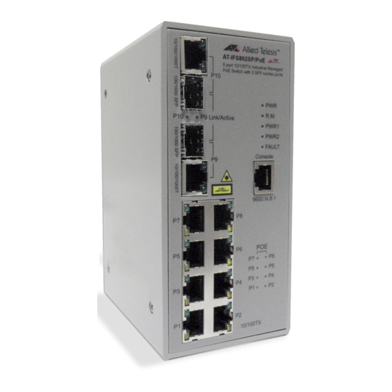
AT-IFS802SP/POE(W)-80 User Manual Chapter 2 Hardware Description In this paragraph, it will describe the Industrial switch’s hardware spec, port, cabling information, and wiring installation. 2.1 Physical Dimension 8 10/100TX w/ X-Ring Managed Industrial Switch dimension (W x D x H) is 72mm x 105mm x 152mm 2.2 Front Panel... -
Page 15: Bottom View
AT-IFS802SP/POE(W)-80 User Manual 2.3 Bottom View The bottom panel of the 8 10/100TX w/ X-Ring Managed Industrial Switch has one terminal block connector of two DC power inputs and one fault alarm. Bottom Panel of the industrial switch... -
Page 16: Led Indicators
AT-IFS802SP/POE(W)-80 User Manual 2.4 LED Indicators The diagnostic LEDs that provide real-time information of system and optional status are located on the front panel of the industrial switch. The following table provides the description of the LED status and their meanings for the switch. -
Page 17: Chapter 3 Hardware Installation
AT-IFS802SP/POE(W)-80 User Manual Chapter 3 Hardware Installation In this paragraph, we will describe how to install the 8 10/100TX w/ X-Ring Managed Industrial Switch and the installation points attended to it. 3.1 Installation Steps Unpack the Industrial switch Check if the DIN-Rail is screwed on the Industrial switch or not. If the DIN-Rail is not screwed on the Industrial switch, please refer to DIN-Rail Mounting section for DIN-Rail installation. -
Page 18: Din-Rail Mounting
AT-IFS802SP/POE(W)-80 User Manual 3.2 DIN-Rail Mounting The DIN-Rail is screwed on the industrial switch when out of factory. If the DIN-Rail is not screwed on the industrial switch, please see the following pictures to screw the DIN-Rail on the switch. Follow the steps below to hang the industrial switch. -
Page 19: Wall Mount Plate Mounting
AT-IFS802SP/POE(W)-80 User Manual 3.3 Wall Mount Plate Mounting Follow the steps below to mount the industrial switch with wall mount plate. Remove the DIN-Rail from the industrial switch; loose the screws to remove the DIN-Rail. Place the wall mount plate on the rear panel of the industrial switch. -
Page 20: Wiring The Power Inputs
AT-IFS802SP/POE(W)-80 User Manual 3.4 Wiring the Power Inputs Please follow the steps below to insert the power wire. Insert AC or DC power wires into the contacts 1 and 2 for power 1, or 5 and 6 for power. Tighten the wire-clamp screws for preventing the wires from loosing. -
Page 21: Wiring The Fault Alarm Contact
AT-IFS802SP/POE(W)-80 User Manual 3.5 Wiring the Fault Alarm Contact The fault alarm contacts are in the middle of the terminal block connector as the picture shows below. Inserting the wires, the switch will detect the fault status of the power failure, or port link failure (available for managed model) and then forms an open circuit. -
Page 22: Cabling
AT-IFS802SP/POE(W)-80 User Manual 3.6 Cabling • Use four twisted-pair, Category 5e or above cabling for RJ-45 port connection. The cable between the switch and the link partner (switch, hub, workstation, etc.) must be less than 100 meters (328 ft.) long. - Page 23 AT-IFS802SP/POE(W)-80 User Manual Second, insert the fiber cable of LC connector into the transceiver. LC connector to the transceiver To remove the LC connector from the transceiver, please follow the steps shown below: First, press the upper side of the LC connector to release from the transceiver and pull it out.
-
Page 24: Chapter 4 Network Application
AT-IFS802SP/POE(W)-80 User Manual Chapter 4 Network Application This chapter provides some sample applications to help user to have more actual idea of industrial switch function application. A sample application of the industrial switch is shown as below: 4.1 X-Ring Application The industrial switch supports the X-Ring protocol that can help the network system to recovery from network connection failure within 20ms or less, and make the network system more reliable. -
Page 25: Coupling Ring Application
AT-IFS802SP/POE(W)-80 User Manual 4.2 Coupling Ring Application In the network, it may have more than one X-Ring group. By using the coupling ring function, it can connect each X-Ring for the redundant backup. It can ensure the transmissions between two ring... -
Page 26: Dual Homing Application
AT-IFS802SP/POE(W)-80 User Manual 4.3 Dual Homing Application Dual Homing function is to prevent the connection lose from between X-Ring group and upper level/ core switch. Assign two ports to be the Dual Homing port that is backup port in the X-Ring group. -
Page 27: Chapter 5 Console Management
AT-IFS802SP/POE(W)-80 User Manual Chapter 5 Console Management 5.1 Connecting to the Console Port The supplied cable which one end is RS-232 connector and the other end is RJ-45 connector. Attach the end of RS-232 connector to PC or terminal and the other end of RJ-45 connector to the console port of the switch. -
Page 28: Login In The Console Interface
AT-IFS802SP/POE(W)-80 User Manual 5.3 Login in the Console Interface When the connection between Switch and PC is ready, turn on the PC and run a terminal emulation program or Hyper Terminal and configure its communication parameters to match the following default characteristics of the console port:... -
Page 29: Commands Level
AT-IFS802SP/POE(W)-80 User Manual 5.5 Commands Level Modes Access Method Prompt Exit Method About This Mode1 The user commands available at the user level are a subset of those Begin a session with Enter logout available at the privileged level. User EXEC switch>... -
Page 30: Chapter 6 Web-Based Management
AT-IFS802SP/POE(W)-80 User Manual Chapter 6 Web-Based Management This section introduces the configuration and functions of the Web-Based management. 6.1 About Web-based Management There is an embedded HTML web site residing in flash memory on CPU board of the switch, which offers advanced management features and allows users to manage the switch from anywhere on the network through a standard browser such as Microsoft Internet Explorer. The Web-Based Management supports Internet Explorer 6.0 or later version. And, it is applied for Java Applets for reducing network bandwidth consumption, enhance access speed and present an easy viewing screen. -
Page 31: System Information
AT-IFS802SP/POE(W)-80 User Manual 3. The login screen will appear right after 4. Key in the user name and password. The default user name and password are the same as ‘root’. 5. Press Enter or click the OK button, and then the home screen of the Web-based management appears. Login screen 6.4 System Information User can assign the system name, description, location and contact personnel to identify the switch. -
Page 32: Ip Configuration
AT-IFS802SP/POE(W)-80 User Manual 6.5 IP Configuration The switch is a network device which needs to be assigned an IP address for being identified on the network. Users have to decide a means of assigning IP address to the switch. • DHCP Client : Enable or disable the DHCP client function. When DHCP client function is enabled, the switch will be assigned an IP address from the network DHCP server. The default IP address will be replaced by the assigned IP address on DHCP server. -
Page 33: Dhcp Server
AT-IFS802SP/POE(W)-80 User Manual 6.6 DHCP Server DHCP is the abbreviation of Dynamic Host Configuration Protocol that is a protocol for assigning dynamic IP addresses to devices on a network. With dynamic addressing, a device can have a different IP address every time it connects to the network. In some systems, the device’s IP address can even change while it is still connected. -
Page 34: Client Entries
AT-IFS802SP/POE(W)-80 User Manual 6.6.2 Client Entries When the DHCP server function is enabled, the system will collect the DHCP client information including the assigned IP address, the MAC address of the client device, the IP assigning type, status and lease time. -
Page 35: Tftp
AT-IFS802SP/POE(W)-80 User Manual 6.7 TFTP It provides the functions allowing the user to update the switch firmware via the Trivial File Transfer Protocol (TFTP) server. Before updating, make sure the TFTP server is ready and the firmware image is located on the TFTP server. 6.7.1 Update Firmware • TFTP Server IP Address : Type in your TFTP server IP. • Firmware File Name : Type in the name of the firmware image file to be updated. • Click Apply Update Firmware interface 6.7.2 Restore Configuration You can restore a previous backup configuration from the TFTP server to recover the settings. Before... -
Page 36: Backup Configuration
AT-IFS802SP/POE(W)-80 User Manual 6.7.3 Backup Configuration You can back up the current configuration from flash ROM to the TFTP server for the purpose of recovering the configuration later. It helps you to avoid wasting time on configuring the settings by backing up the configuration. • TFTP Server IP Address : Type in the TFTP server IP. • Backup File Name : Type in the file name. • Click Apply Backup Configuration interface 6.8 System Event Log This page allows the user to decide whether to send the system event log, and select the mode which the system event log will be sent to client only, server only, or both client and server. -
Page 37: System Event Log-Smtp Configuration
AT-IFS802SP/POE(W)-80 User Manual Syslog Configuration interface 6.8.2 System Event Log—SMTP Configuration Simple Mail Transfer Protocol (SMTP) is the standard for email transmissions across the network. You can configure the SMTP server IP, mail subject, sender, mail account, password, and the recipient email addresses which the e-mail alert will send to. There are also five types of event—Device Cold Start, Device Warm Start, Authentication Failure, X-Ring Topology Change, and Port Event—available to be issued as the e-mail alert. Besides, this function provides the authentication mechanism including an authentication step through which the client effectively logs in to the SMTP server during the process of sending e-mail alert. -
Page 38: System Event Log - Event Configuration
AT-IFS802SP/POE(W)-80 User Manual SMTP Configuration interface 6.8.3 System Event Log - Event Configuration Having ticked the Syslog/SMTP checkboxes, the event log/email alert will be sent to the system log server and the SMTP server respectively. Also, Port event log/alert (link up, link down, and both) can be sent to the system log server/SMTP server respectively by setting the trigger condition. - Page 39 AT-IFS802SP/POE(W)-80 User Manual • Port event selection : Also, before the drop-down menu items are available, the Syslog Client Mode selection item on the Syslog Configuration tab and the E-mail Alert selection item on the SMTP Configuration tab must be enabled first. Those drop-down menu items have 3 selections— Link UP, Link Down, and Link UP & Link Down. Disable means no event will be sent to the system log/SMTP server.
-
Page 40: Fault Relay Alarm
AT-IFS802SP/POE(W)-80 User Manual 6.9 Fault Relay Alarm The Fault Relay Alarm function provides the Power Failure and Port Link Down/Broken detection. With both power input 1 and power input 2 installed and the check boxes of power 1/power 2 ticked, the FAULT LED indicator will then be possible to light up when any one of the power failures occurs. - Page 41 AT-IFS802SP/POE(W)-80 User Manual • SNTP Client : Enable/disable SNTP function to get the time from the SNTP server. • Daylight Saving Time : This is used as a control switch to enable/disable daylight saving period and daylight saving offset. Users can configure Daylight Saving Period and Daylight Saving Offset in a certain period time and offset time while there is no need to enable daylight saving function.
- Page 42 AT-IFS802SP/POE(W)-80 User Manual • SNTP Sever URL : Set the SNTP server IP address. Y ou can assign a local network time server IP address or an internet time server IP address. • Switch Timer : When the switch has successfully connected to the SNTP server whose IP address was assigned in the column field of SNTP Server URL, the current coordinated time is displayed here. • Daylight Saving Period: Set up the Daylight Saving beginning date/time and Daylight Saving ending date/time. Please key in the value in the format of ‘YYYYMMDD’ and ‘HH:MM’ (leave a...
-
Page 43: Ip Security
AT-IFS802SP/POE(W)-80 User Manual 6.11 IP Security IP security function allows the user to assign 10 specific IP addresses that have permission to manage the switch through the http and telnet services for the securing switch management. The purpose of giving the limited IP addresses permission is to allow only the authorized personnel/device can do the management task on the switch. -
Page 44: User Authentication
AT-IFS802SP/POE(W)-80 User Manual 6.12 User Authentication Change web management login user name and password for the management security issue. • User name : Type in the new user name (The default is ‘root’) • Password : Type in the new password (The default is ‘root’) • Confirm password : Re-type the new password • And then, click Apply User Authentication interface 6.13 Port Statistics... -
Page 45: Port Control
AT-IFS802SP/POE(W)-80 User Manual Port Statistics interface 6.14 Port Control In Port control you can configure the settings of each port to control the connection parameters, and the status of each port is listed beneath. • Port : Use the scroll bar and click on the port number to choose the port to be configured. • State : Current port state. The port can be set to disable or enable mode. If the port state is set as ‘Disable’, it will not receive or transmit any packet. -
Page 46: Port Trunk
AT-IFS802SP/POE(W)-80 User Manual Port Control interface 6.15 Port Trunk Port trunking is the combination of several ports or network cables to expand the connection speed beyond the limits of any one single port or network cable. Link Aggregation Control Protocol (LACP), which is a protocol running on layer 2, provides a standardized means in accordance with IEEE 802.3ad... - Page 47 AT-IFS802SP/POE(W)-80 User Manual • Work ports : This column field allows the user to type in the total number of active port up to four. With LACP static trunk group, e.g. you assign four ports to be the members of a trunk group whose work ports column field is set as two; the exceed ports are standby/ redundant ports and can be aggregated if working ports fail. If it is a static trunk group (non-LACP), the number of work ports must equal the total number of group member ports.
-
Page 48: Aggregator Information
AT-IFS802SP/POE(W)-80 User Manual 6.15.2 Aggregator Information • LACP disabled Having set up the aggregator setting with LACP disabled, you will see the local static trunk group information on the tab of Aggregator Information. Assigning 2 ports to a trunk group with LACP disabled Static Trunking Group information •... - Page 49 AT-IFS802SP/POE(W)-80 User Manual • LACP enabled Having set up the aggregator setting with LACP enabled, you will see the trunking group information between two switches on the tab of Aggregator Information. Switch 1 configuration System Priority of the trunk group. The default is 1.
- Page 50 AT-IFS802SP/POE(W)-80 User Manual Switch 2 configuration Switch 2 configuration interface 1. Set System Priority of the trunk group. The default is 1. 2. Select a trunk group ID by pull down the drop-down menu bar. 3. Enable LACP. 4. Include the member ports by clicking the Add button after selecting the port number and the column field of Work Ports changes automatically.
-
Page 51: State Activity
AT-IFS802SP/POE(W)-80 User Manual 6.15.3 State Activity Having set up the LACP aggregator on the tab of Aggregator Setting, you can configure the state activity for the members of the LACP trunk group. You can tick or cancel the checkbox beside the state label. When you remove the tick mark of the port and click , the port state Apply activity will change to Passive. • Active : The port automatically sends LACP protocol packets. -
Page 52: Port Mirroring
AT-IFS802SP/POE(W)-80 User Manual 6.16 Port Mirroring The Port mirroring is a method for monitor traffic in switched networks. Traffic through ports can be monitored by one specific port, which means traffic goes in or out monitored (source) ports will be duplicated into mirror (destination) port. • Destination Port : There is only one port can be selected to be destination (mirror) port for monitoring both RX and TX traffic which come from source port. Or, use one of two ports for monitoring RX traffic only and the other one for TX traffic only. User can connect mirror port to LAN analyzer or Netxray. • Source Port : The ports that user wants to monitor. All monitored port traffic will be copied to... -
Page 53: Rate Limiting
AT-IFS802SP/POE(W)-80 User Manual 6.17 Rate Limiting You can set up every port’s bandwidth rate and frame limitation type. • Ingress Limit Frame type : select the frame type that wants to filter. There are four frame types for selecting: > Broadcast/Multicast/Flooded Unicast > Broadcast/Multicast > Broadcast only > Broadcast/Multicast/Flooded Unicast, Broadcast/Multicast and Broadcast only types are only for ingress frames. The egress rate only supports All type. -
Page 54: Vlan Configuration
AT-IFS802SP/POE(W)-80 User Manual 6.18 VLAN configuration A Virtual LAN (VLAN) is a logical network grouping that limits the broadcast domain, which would allow you to isolate network traffic, so only the members of the same VLAN will receive traffic from the ones of the same VLAN. Basically, creating a VLAN on a switch is logically equivalent of reconnecting a group of network devices to another Layer 2 switch. - Page 55 AT-IFS802SP/POE(W)-80 User Manual VLAN – Port Based interface Port Based then press • Pull down the selection item and focus on to set the VLAN Apply Operation Mode in Port Based mode. • Click to add a new VLAN group (The maximum VLAN groups are up to 64).
-
Page 56: Q Vlan
AT-IFS802SP/POE(W)-80 User Manual VLAN—Port Based Edit/Delete interface Delete • to delete the VLAN. • to modify group name, VLAN ID, or add/remove the members of the existing Edit VLAN group. Remember to execute the “Save Configuration” action, otherwise the new [note] configuration will lose when switch power off. 6.18.2 802.1Q VLAN Virtual Local Area Network (VLAN) can be implemented on the switch to logically create different broadcast domain. -
Page 57: Q Configuration
AT-IFS802SP/POE(W)-80 User Manual 802.1Q Configuration 802.1Q then press to set the VLAN Operation • Pull down the selection item and focus on Mode in 802.1Q mode. • Enable GVRP Protocol : GVRP (GARP VLAN Registration Protocol) is a protocol that facilitates control of virtual local area networks (VLANs) within a larger network. GVRP conforms to the IEEE 802.1Q specification, which defines a method of tagging frames with... - Page 58 AT-IFS802SP/POE(W)-80 User Manual > Hybrid Link: A segment which consists of Access and Trunk links. The hybrid port has both the features of access and trunk ports. A hybrid port has a PVID belonging to a particular VLAN, and it also forwards the specified tagged-frames for the purpose of VLAN communication across switches.
-
Page 59: Rapid Spanning Tree
AT-IFS802SP/POE(W)-80 User Manual Group Configuration interface > Click Apply 6.19 Rapid Spanning Tree The Rapid Spanning Tree Protocol (RSTP) is an evolution of the Spanning Tree Protocol and provides for faster spanning tree convergence after a topology change. The system also supports STP and the system will auto-detect the connected device that is running STP or RSTP protocol. -
Page 60: Port Configuration
AT-IFS802SP/POE(W)-80 User Manual Follow the rule as below to configure the MAX Age, Hello Time, and Forward Delay Time. [note] 2 x (Forward Delay Time value –1) > = Max Age value >= 2 x (Hello Time value RSTP System Configuration interface 6.19.2 Port Configuration This web page provides the port configuration interface for RSTP. You can assign higher or lower priority to each port. -
Page 61: Snmp Configuration
AT-IFS802SP/POE(W)-80 User Manual RSTP Port Configuration interface 6.20 SNMP Configuration Simple Network Management Protocol (SNMP) is the protocol developed to manage nodes (servers, workstations, routers, switches and hubs etc.) on an IP network. SNMP enables network administrators to manage network performance, find and solve network problems, and plan for network growth. -
Page 62: Trap Configuration
AT-IFS802SP/POE(W)-80 User Manual • Agent Mode : Select the SNMP version that you want to use it. And then click Change switch to the selected SNMP version mode. SNMP System Configuration interface 6.20.2 Trap Configuration A trap manager is a management station that receives the trap messages generated by the switch. If no trap manager is defined, no traps will be issued. To define a management station as... -
Page 63: Snmpv3 Configuration
AT-IFS802SP/POE(W)-80 User Manual 6.20.3 SNMPV3 Configuration Configure the SNMP V3 function. Context Table Configure SNMP v3 context table. Assign the context name of context table. Click to add context name. Click to remove unwanted context name. Remove User Table Configure SNMP v3 user table.. • User ID : set up the user name. • Authentication Password : set up the authentication password. • Privacy Password : set up the private password. -
Page 64: Qos Configuration
AT-IFS802SP/POE(W)-80 User Manual Access Table Configure SNMP v3 access table. • Context Prefix : set up the context name. • Group Name : set up the group. • Security Level : select the access level. • Context Match Rule : select the context match rule. -
Page 65: Port-Based Priority
AT-IFS802SP/POE(W)-80 User Manual Use a strict priority scheme: Always the higher queue will be processed first, except the > higher queue is empty. Priority Type: There are 5 priority type selections available—Port-based, TOS only, COS > only, TOS first, and COS first. Disable means no priority type is selected. Click to have the configuration take effect. • Click to have the configuration take effect. Apply QoS Configuration interface 6.21.2 Port-based Priority... -
Page 66: Cos Configuration
AT-IFS802SP/POE(W)-80 User Manual 6.21.3 COS Configuration Set up the COS priority level. With the drop-down selection item of Priority Type above being selected as COS only/COS first, this control item will then be available to set the queuing policy for each port. • COS priority : Set up the COS priority level 0~7 - High, Middle, Low, Lowest. -
Page 67: X-Ring
AT-IFS802SP/POE(W)-80 User Manual The switch support IP multicast, you can enable IGMP protocol on web management’s switch setting advanced page, then the IGMP snooping information displays. IP multicast addresses range are from 224.0.0.0 through 239.255.255.255. • IGMP Protocol : enable or disable the IGMP protocol. - Page 68 AT-IFS802SP/POE(W)-80 User Manual • Enable Ring : To enable the X-Ring function, tick the checkbox beside the Enable Ring string label. If this checkbox is not ticked, all the ring functions are unavailable. Enable Ring Master: Tick the checkbox to enable this switch to be the ring master.
-
Page 69: Lldp Configuration
AT-IFS802SP/POE(W)-80 User Manual 6.24 LLDP Configuration Link Layer Discovery Protocol (LLDP) is defined in the IEEE 802.1AB, it is an emerging standard which provides a solution for the configuration issues caused by expanding LANs. LLDP specifically defines a standard method for Ethernet network devices such as switches, routers and wireless LAN access points to advertise information about themselves to other nodes on the network and store the information they discover. LLDP runs on all 802 media. The protocol runs over the data-link layer only, allowing two systems running different network layer protocols to learn about each other. -
Page 70: Port Configuration
AT-IFS802SP/POE(W)-80 User Manual 802.1x System Configuration interface 6.25.2 Port Configuration You can configure the 802.1x authentication state for each port. The state provides Disable, Accept, Reject, and Authorize. • Reject : The specified port is required to be held in the unauthorized state. • Accept : The specified port is required to be held in the authorized state. • Authorize : The specified port is set to the Authorized or Unauthorized state in accordance with the outcome of an authentication exchange between the Supplicant and the authentication server. -
Page 71: Misc Configuration
AT-IFS802SP/POE(W)-80 User Manual 6.25.3 Misc Configuration • Quiet Period: Set the period which the port doesn’t try to acquire a supplicant. • TX Period : Set the period port waits for retransmit next EAPOL PDU during an authentication session. • Supplicant Timeout : Set the period of time the switch waits for a supplicant response to an EAP request. -
Page 72: Mac Filtering
AT-IFS802SP/POE(W)-80 User Manual Add the Static MAC Address You can add static MAC address in the switch MAC table here. • MAC Address : Enter the MAC address of the port that should permanently forward traffic, regardless of the device network activity. • Port No. : Pull down the selection menu to select the port number. • Click Apply • If you want to delete the MAC address from filtering table, select the MAC address and click Delete Static MAC Addresses interface 6.26.2 MAC Filtering... -
Page 73: All Mac Addresses
AT-IFS802SP/POE(W)-80 User Manual • MAC Address : Enter the MAC address that you want to filter. • Click • If you want to delete the MAC address from the filtering table, select the MAC address and click Delete 6.26.3 All MAC Addresses You can view all of the MAC addresses learned by the selected port. • Select the port number. • The selected port of static & dynamic MAC address information will be displayed in here. •... - Page 74 AT-IFS802SP/POE(W)-80 User Manual Multicast Filtering interface...
-
Page 75: Power Over Ethernet
AT-IFS802SP/POE(W)-80 User Manual 6.27 Power over Ethernet This segment shows the Power over Ethernet function. PoE Status • Actual Power Consumption : This column shows the real-time total power consumption. • Main Supply Voltage : This column shows the output voltage of the system for PoE ports. - Page 76 AT-IFS802SP/POE(W)-80 User Manual • Power Limit From : Check it to decide the power limit method. Classification: When this check box is ticked, the system will limit the power supply to the powered device in accordance with the related class.
-
Page 77: Factory Default
AT-IFS802SP/POE(W)-80 User Manual 6.28 Factory Default Reset switch to default configuration. Click to reset all configurations to the default value. Default Factory Default interface 6.29 Save Configuration Save all configurations that you have made in the system. To ensure the all configuration will be saved. Click to save the all configuration to the flash memory. Save Flash Save Configuration interface 6.30 System Reboot Reboot the switch in software reset. Click to reboot the system. Reboot System Reboot interface... -
Page 78: Troubles Shooting
AT-IFS802SP/POE(W)-80 User Manual Troubles shooting • Verify that is using the right power cord/adapter (DC 24-48V), please don’t use the power adapter with DC output higher than 48V, or it may damage this device. • Select the proper UTP/STP cable to construct the user network. Use unshielded twisted-pair (UTP) or shield twisted-pair (STP) cable for RJ-45 connections that depend on the connector type the switch equipped: 100Ω Category 3, 4 or 5 cable for 10Mbps connections, 100Ω Category... -
Page 79: Appendix A-Rj-45 Pin Assignment
AT-IFS802SP/POE(W)-80 User Manual Appendix A—RJ-45 Pin Assignment RJ-45 Pin Assignments • The UTP/STP ports will automatically sense for Fast Ethernet (10Base-T/100Base-TX connections), or Gigabit Ethernet (10Base-T/100Base-TX/1000Base-T connections). Auto MDI/MDIX means that the switch can connect to another switch or workstation without changing straight through or crossover cabling. See the figures below for straight through and crossover cable schematic. - Page 80 AT-IFS802SP/POE(W)-80 User Manual • 10/100Base-TX Cable Schematic The following two figures show the 10/100Base-TX cable schematic. Straight-through cable schematic Cross over cable schematic • 10/100/1000Base-TX Pin outs The following figure shows the 10/100/1000 Ethernet RJ-45 pin outs.
- Page 81 AT-IFS802SP/POE(W)-80 User Manual • 10/100/1000Base-TX Cable Schematic Straight through cables schematic Cross over cables schematic...
-
Page 82: Pin Assignments Of Poe
AT-IFS802SP/POE(W)-80 User Manual RJ-45 Pin Assignments of POE With 100BASE-TX/10BASE-T cable, pins 1 and 2 are used for transmitting data, and pins 3 and 6 for receiving data; pins 4, 5, 7 and 8 are used for power supplying. •... -
Page 83: Appendix B-Command Sets
AT-IFS802SP/POE(W)-80 User Manual Appendix B—Command Sets Commands Set List User EXEC Privileged EXEC Global configuration VLAN database Interface configuration System Commands Set Allied T elesis Commands Level Description Example show config Show switch configuration switch>show config show terminal Show console information switch#show terminal Save user configuration into write memory... - Page 84 AT-IFS802SP/POE(W)-80 User Manual admin password Specifies a password switch(config)#admin password xxxxxx [Password] (maximum 10 words) Show administrator show admin switch#show admin information dhcpserver enable Enable DHCP Server switch(config)#dhcpserver enable Dhcpserver disable Disable DHCP Server switch(config)#no dhcpserver dhcpserver lowip Configure low IP address switch(config)#dhcpserver lowip [Low IP] for IP pool 192.168.1.100...
-
Page 85: Port Commands Set
AT-IFS802SP/POE(W)-80 User Manual Port Commands Set Allied T elesis Commands Level Description Example interface fastEthernet Choose the port for switch(config)#interface fastEthernet 2 [Portid] modification. Use the duplex configuration command to switch(config)#interface fastEthernet 2 duplex [full | half] specify the duplex mode of switch(config-if)#duplex full operation for Fast Ethernet. - Page 86 AT-IFS802SP/POE(W)-80 User Manual Set interface output bandwidth. Rate Range is from 100 kbps to 102400 switch(config)#interface fastEthernet 2 bandwidth out [Value] kbps or to 256000 kbps for switch(config-if)#bandwidth out 100 giga ports and zero means no limit. Show interfaces bandwidth switch(config)#interface fastEthernet 2 show bandwidth control...
-
Page 87: Trunk Commands Set
AT-IFS802SP/POE(W)-80 User Manual Trunk Commands Set Allied T elesis Commands Level Description Example aggregator priority Set port group system switch(config)#aggregator priority 22 [1~65535] priority aggregator activityport [Group ID] Set activity port switch(config)#aggregator activityport 2 [Port Numbers] Assign a trunk group with LACP active. [GroupID] :1~3... -
Page 88: Vlan Commands Set
AT-IFS802SP/POE(W)-80 User Manual VLAN Commands Set Allied T elesis Commands Level Description Example vlan database Enter VLAN configure mode switch#vlan database switch(vlan)#vlanmode portbase Vlanmode [portbase| 802.1q | To set switch VLAN mode. switch(vlan)#vlanmode 802.1q gvrp] switch(vlan)#vlanmode gvrp no vlan No VLAN Switch(vlan)#no vlan... - Page 89 AT-IFS802SP/POE(W)-80 User Manual vlan 8021q trunk [PortNumber] Assign a access link for switch(vlan)#vlan 8021q trunk 3 access- access-link untag VLAN by trunk group link untag 33 [UntaggedVID] vlan 8021q trunk switch(vlan)#vlan 8021q trunk 3 trunk-link [PortNumber] tag 2,3,6,99 Assign a trunk link for...
-
Page 90: Spanning Tree Commands Set
AT-IFS802SP/POE(W)-80 User Manual Spanning Tree Commands Set Allied T elesis Commands Level Description Example spanning-tree enable Enable spanning tree switch(config)#spanning-tree enable spanning-tree priority Configure spanning tree switch(config)#spanning-tree priority [0~61440] priority parameter 32768 Use the spanning-tree max- age global configuration command to change the interval between messages the spanning tree receives from the root switch. - Page 91 AT-IFS802SP/POE(W)-80 User Manual Use the spanning-tree port-priority interface configuration command to stp-path-priority configure a port priority switch(config)#interface fastEthernet 2 [Port Priority] that switch(config-if)#stp-path-priority 128 is used when two switches tie for position as the root switch. stp-admin-p2p Admin P2P of STP priority switch(config)#interface fastEthernet 2 [Auto|True|False] on this interface. switch(config-if)#stp-admin-p2p Auto...
-
Page 92: Qos Commands Set
AT-IFS802SP/POE(W)-80 User Manual QOS Commands Set Allied Telesis Commands Level Description Example qos policy Select QOS policy switch(config)#qos policy weighted- [weighted-fair|strict] scheduling fair qos prioritytype [port-based|cos-only|tos- Setting of QOS priority type switch(config)#qos prioritytype only|cos-first|tos-first] qos priority portbased [Port] Configure Port-based switch(config)#qos priority portbased [lowest|low|middle|high] Priority 1 low... -
Page 93: Igmp Commands Set
AT-IFS802SP/POE(W)-80 User Manual IGMP Commands Set Allied T elesis Commands Level Description Example Enable IGMP snooping igmp enable switch(config)#igmp enable function Set IGMP query to auto Igmp-query auto switch(config)#Igmp-query auto mode Set IGMP query to force Igmp-query force switch(config)#Igmp-query force mode igmp unregister... -
Page 94: Multicast Filtering Commands Set
AT-IFS802SP/POE(W)-80 User Manual Multicast Filtering Commands Set Allied T elesis Commands Level Description Example Switch(config)#interface fastEthernet 2 multicast-filtering Configure multicast filtering switch(config-if)#multicast-filtering [IP-Addr] entry of interface 228.1.1.1 Switch(config)#interface fastEthernet 2 no multicast-filtering Remove multicast filtering switch(config-if)#no multicast-filtering [IP-Addr] entry of interface 228.1.1.1 LLDP Commands Set Allied T elesis Commands Level... -
Page 95: Snmp Commands Set
AT-IFS802SP/POE(W)-80 User Manual SNMP Commands Set Allied T elesis Commands Level Description Example snmp system-name Set SNMP agent system switch(config)#snmp system-name l2switch [System Name] name snmp system-location Set SNMP agent system switch(config)#snmp system-location lab [System Location] location snmp system-contact Set SNMP agent system switch(config)#snmp system-contact... - Page 96 AT-IFS802SP/POE(W)-80 User Manual snmpv3 mibview view [View Name] type Configure the mibview table switch(config)#snmpv3 mibview view V1 [Excluded|Included] of SNMPV3 agent type Excluded sub-oid 1.3.6.1 sub-oid [OID] show snmp Show SNMP configuration switch#show snmp no snmp community- Remove the specified switch(config)#no snmp community-strings strings [Community] community. public no snmp-server host Remove the SNMP server...
-
Page 97: Port Mirroring Commands Set
AT-IFS802SP/POE(W)-80 User Manual Port Mirroring Commands Set Allied T elesis Commands Level Description Example monitor Configure source port of switch(config)#interface fastEthernet 2 [RX|TX|Both] monitor function switch(config-if)#monitor RX Set RX destination port of monitor rx [Port ID] switch(config)#monitor rx 2 monitor function Set TX destination port of monitor tx... -
Page 98: Commands Set
AT-IFS802SP/POE(W)-80 User Manual 802.1x Commands Set Allied T elesis Commands Level Description Example Use the 802.1x global 8021x enable configuration command to switch(config)# 8021x enable enable 802.1x protocols. Use the 802.1x 8021x system radiusip system radius IP global switch(config)# 8021x system radiusip [IP address] configuration command to 192.168.1.1 change the radius server IP. - Page 99 AT-IFS802SP/POE(W)-80 User Manual Use the 802.1x misc max 8021x misc request global configuration switch(config)# 8021x misc maxrequest 3 maxrequest [number] command to set the MAX requests. Use the 802.1x misc reauth 8021x misc period global configuration switch(config)# 8021x misc reauthperiod reauthperiod [sec.] command to set the reauth 3000 period. Use the 802.1x port state...
-
Page 100: Tftp Commands Set
AT-IFS802SP/POE(W)-80 User Manual TFTP Commands Set Allied T elesis Commands Level Description Example Save configuration to TFTP backup and need to specify the IP switch(config)#backup flash:backup_cfg flash:backup_cfg of TFTP server and the file name of image. Get configuration from TFTP server and need restore to specify the IP of TFTP switch(config)#restore flash:restore_cfg... -
Page 101: Systemlog, Smtp And Event Commands Set
AT-IFS802SP/POE(W)-80 User Manual SystemLog, SMTP and Event Commands Set Allied T elesis Commands Level Description Example systemlog ip Set System log server IP switch(config)# systemlog ip [IP address] address. 192.168.1.100 systemlog mode Specified the log mode switch(config)# systemlog mode both [client|server|both] show systemlog Displays system log. Switch>show systemlog Show system log client &... -
Page 102: Fault Relay Alarm Commands Set
AT-IFS802SP/POE(W)-80 User Manual Disable cold start event switch(config)#no event device-cold- no event device-cold-start type start no event authentication- Disable Authentication switch(config)#no event authentication- failure failure event typ failure no event ring-topology- Disable X-ring topology switch(config)#no event ring-topology- change changed event type change Disable port event for... -
Page 103: Sntp Commands Set
AT-IFS802SP/POE(W)-80 User Manual SNTP Commands Set Allied T elesis Commands Level Description Example sntp enable Enable SNTP function switch(config)#sntp enable Enable daylight saving time, if SNTP function is inactive, sntp daylight switch(config)#sntp daylight this command can’t be applied. Set period of daylight... -
Page 104: X-Ring Commands Set
AT-IFS802SP/POE(W)-80 User Manual X-ring Commands Set Allied T elesis Commands Level Description Example ring enable Enable X-ring switch(config)#ring enable ring master Enable ring master switch(config)#ring master ring couplering Enable couple ring switch(config)#ring couplering ring dualhoming Enable dual homing switch(config)#ring dualhoming ring ringport Configure 1st/2nd Ring [1st Ring Port] [2nd Ring... -
Page 105: Poe Commands Set
AT-IFS802SP/POE(W)-80 User Manual PoE Commands Set Allied T elesis Commands Level Description Example Enter POE configure mode switch#poe system knockoff-disabled Set PoE system Port switch(poe)# system knockoff-disabled [Enable|Disable] Knockoff Disabled disable system ac-disconnect Set PoE system AC switch(poe)# system ac-disconnect [Enable|Disable] Disconnect disable...
Need help?
Do you have a question about the AT-IFS802SP/POE and is the answer not in the manual?
Questions and answers