Table of Contents
Advertisement
Advertisement
Table of Contents

Related Manuals for Hofmann geodyna 2600


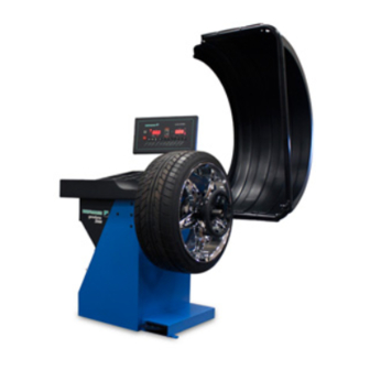
Summary of Contents for Hofmann geodyna 2600
- Page 1 2600 Operation manual Car wheel balancer Form ZEEWB703D 2800 2600...
-
Page 2: Table Of Contents
By exact adjustment of the two wheel components relative to each other optimum wheel running conditions or at least balance weight minimisation can be achieved. Operation manual geodyna 2600 EEWB703D... -
Page 3: Safety Rules And Function
Wear suitable protective clothing and accessories (e. g. goggles, safety shoes, helmet). For further safety rules to be observed, please refer to the individual chapters. Operation manual geodyna 2600 EEWB703D... - Page 4 European Union and is part of the standard equipment. The measuring run may only be started with closed guard. The electronic unit can be programmed via code C13 so that mea- surement is started by closing of the guard. Operation manual geodyna 2600 EEWB703D...
- Page 5 (e. g. forklift truck, platform truck). Note When lifting the machine bear in mind the centre of gravity of the machine and avoid oscillating movements. Operation manual geodyna 2600 EEWB703D...
-
Page 6: Installation Of The Machine
Fusing is by the customer before the plug connector, using a 15 amp circuit breaker. The electrical diagram is illustrated in § 16. The machine operates internally on a line voltage of 230 V because the voltage is regulated by an integrated transformer. Operation manual geodyna 2600 EEWB703D... - Page 7 7 G/OZ Switches over the weight unit for unbalance readings (grammes or ounces). G Readings in grammes Oz Readings in ounces When the machine is switched on the weight unit set with code C3 is active. Operation manual geodyna 2600 EEWB703D...
-
Page 8: Controls And Displays
(using service code). Readouts stay in RV mode until deselected by pressing the key again. S/D (key pressed on bottom): - Function key to select display of dynamic or static unbalance (S/D key). Operation manual geodyna 2600 EEWB703D... - Page 9 Readout display changes to single-plane. Both loca- tion displays are active and work in parallel. Distance and diameter dimensions have no effect and are preset to nominal values. All special functions are inactive and cannot be selected. Operation manual geodyna 2600 EEWB703D...
- Page 10 8 SPOKE: Hidden spoke placement (HSP) mode is selected. 9 Number of spokes Number of spokes for hidden spoke placement. Holding the SPOKE key pressed rotate the wheel to set the number of spokes between 3 and 12. Operation manual geodyna 2600 EEWB703D...
- Page 11 Note When the wheel is rotated manually, the SAPE symbol will not light up. 5 ALU+ lights whenever ALU+ is chosen. 6 OK lights whenever in two-plane mode both imbalance readouts are 0.00. Operation manual geodyna 2600 EEWB703D...
- Page 12 This lock is designed only to facilitate orientation of the wheel and must not be used for braking the main shaft. Operation manual geodyna 2600 EEWB703D...
- Page 13 E900 - Fig. 18 Unknown machine model. E901 - Fig. 19 The machine is not calibrated. E89 - Fig. 20 A key is jammed at power-on. • Find and release the jammed key, call service if neces- sary. Operation manual geodyna 2600 EEWB703D...
-
Page 14: Turning On The Machine
Damage is not covered under warranty. C10 804 - Fig. 27 Line voltage too high. Damage to the electronic unit of the machine is likely! • Turn off machine immediately. Damage is not covered under warranty. Operation manual geodyna 2600 EEWB703D... - Page 15 • cancel compensation by pressing and holding the FINE key (Fig. 11b, item 11) and rotating the wheel, or by switching the machine off for a few seconds. In the right display, 0 is read out. Operation manual geodyna 2600 EEWB703D...
-
Page 16: Clamping The Wheel
2 Rim 3 Clamping head with clamping nut Fig. 30 Universal clamping adapter for clamping stud hole located wheels or wheels with closed rim. 1 Rim with center bore (center bore location) 2 Closed rim Operation manual geodyna 2600 EEWB703D... - Page 17 (Fig. 31, items 1 and 3) and rotating the wheel until the desired values are read out. On releasing the function key the input is retained until another input is made. Operation manual geodyna 2600 EEWB703D...
-
Page 18: Entry Of Balancing Mode And Wheel Size
(Alu 3P) attached in hidden position in the rim disc Alu 4 Hammer-on weight on left rim flange, adhesive weight attached to right bead seat Alu 5 Hammer-on weight on right rim flange, adhesive weight attached to left bead seat Operation manual geodyna 2600 EEWB703D... - Page 19 • To enter the rim width, press and hold the function key (Fig. 34, item 1). • Rotate the wheel while the key is pressed in order to set the value for the rim width on the display, and then release the key. Operation manual geodyna 2600 EEWB703D...
- Page 20 Alu 5 Hammer-on weight on right rim flange, adhesive Alu 4 weight attached to left bead seat 15.5 Point of application of gauge arm Given weight position Alu 5 Point of appliction of gauge arm = weight position 15.5 Operation manual geodyna 2600 EEWB703D...
- Page 21 • Press and hold the key for distance (Fig. 38, item 1). • Holding the key pressed, rotate the wheel to enter the distance previously indicated on the scale. • Release t he key. By pressing the key the distance can be viewed once again. Operation manual geodyna 2600 EEWB703D...
- Page 22 The symbol for the inner weight is viewed on the display (Fig. 40d). An audible signal is given when the distance has been stored. • Return the gauge arm for distance and diameter to its home position. • Start the measuring run. Operation manual geodyna 2600 EEWB703D...
- Page 23 • Swing the gauge arm in and return it to its home posi- tion. • Firmly press the adhesive weight on the rim by hand. Fit the second adhesive weight for AP2 in the same manner. Operation manual geodyna 2600 EEWB703D...
- Page 24 The symbol for the inner weight is viewed on the display (Fig. 42d). An audible signal is given when the distance has been stored. • Return the gauge arm for distance and diameter to its home position. • Start the measuring run. Operation manual geodyna 2600 EEWB703D...
- Page 25 (Fig. 44). • Press and hold the key (Fig. 44, item 1 - 3) and rotate the wheel to set the values. • Release the key as soon as the desired value is read out. Operation manual geodyna 2600 EEWB703D...
- Page 26 7.2.9 Correction of inputs after measurement Upon operation of the FINE key the electronic unit accepts the new input, processes it and then reads out the corrected measured data without need to repeat the measuring run. Operation manual geodyna 2600 EEWB703D...
- Page 27 Fig. 48 Example of display and correction of the righthand correction plane 1 Display of amount of unbalance inch mm 2 Display of correction position - only the arrow-heads light up 3 Position of balance weight on rim START Operation manual geodyna 2600 EEWB703D...
-
Page 28: Balancing The Wheel
• Pull the gauge arm towards application position. The display shows the dimension for the first distance, which de- creases as the gauge is approached. At 0 ±1 an audible signal reached. Operation manual geodyna 2600 EEWB703D... - Page 29 The direction to be indexed and the correction position are indicated by both direction indicators (Fig. 53). For correction diameter and possibilities of correction of static unbalance see Fig. 54. Operation manual geodyna 2600 EEWB703D...
- Page 30 • For balancing modes Alu 2 and Alu 3 fit a balance weight in hidden position inside the rim; in this case the correction diameter for static unbalance correction lies inside the rim (Fig. 54.4). 54.3 54.4 Operation manual geodyna 2600 EEWB703D...
- Page 31 The spoke LED lights up and the number of spokes is displayed (Fig. 57). The number of spokes can be chosen between 3 and 12. CALIBRATE SPOKE Operation manual geodyna 2600 EEWB703D...
-
Page 32: Hidden Spoke Placement
Alu 2, Alu 2P or Alu 3, Alu 3P. • In the reading “Wheel data” press twice the key for bal- ancing mode and set number of spokes to 0. Operation manual geodyna 2600 EEWB703D... - Page 33 Code C4 Compen- sation of clamping means cannot be stored in the permanent memory. The possible changes of codes and the necessary inputs are described in the following. Operation manual geodyna 2600 EEWB703D...
-
Page 34: Changing Modes Of Operation
Fig. 67 Selecting suppression of minor unbalance readings 0 = Suppression off 1* to 2 = Suppression on to 0 The selected mode of operation can be transferred to the permanent memory. to 1 * = Factory adjusted mode Operation manual geodyna 2600 EEWB703D... - Page 35 • Make sure that the wheel is not blocked by tools or the like. to 1 0 = No braking 1* = Braking The selected mode of operation can be transferred to the permanent memory. * = Factory adjusted mode Operation manual geodyna 2600 EEWB703D...
- Page 36 Factory-adjusted to 0.25 oz Read out limit, e. g. 0.25 oz Select another limit, e. g. 0.50 oz The selected mode of operation can be transferred to the permanent memory. * = Factory adjusted mode Operation manual geodyna 2600 EEWB703D...
- Page 37 0* = Start via START key 1 to 13 = Start via wheel guard The selected mode of operation can be transferred to the to 0 permanent memory. to 1 * = Factory adjusted mode Operation manual geodyna 2600 EEWB703D...
- Page 38 It is possible to store up to 4 wheel profiles. The following values (if available) are stored: - Nominal wheel dimensions - Values measured with the gauge arm - Weight positions - Positions for relocation See also C17 Operation manual geodyna 2600 EEWB703D...
- Page 39 • Press the CODE key for the 2nd step. • Press and hold FINE key and rotate the wheel to set the desired state: to 1 0 = Do not clear the error memory 1 = Clear error memory Operation manual geodyna 2600 EEWB703D...
- Page 40 With this wheel type it is not possible to choose a balancing mode. E8 - Fig. 87 Valve position was not entered (error code only in Pro-Match program). • Position valve at 12:00 o’clock and press the PRO MATCH key. Operation manual geodyna 2600 EEWB703D...
-
Page 41: Error Codes
The clamping nut is not tight, the main shaft accelerates too quickly. The machine will stop. • Firmly tighten the clamping nut, or if the wheel is very small press the START key a little bit longer. Operation manual geodyna 2600 EEWB703D... - Page 42 • Find and release the key, or call service. E92 - Fig. 95 Gauge arm defective. • Call service. • As long as the gauge arm is defective, enter by press- ing the distance key and rotating the wheel (§ 7.2.3). Operation manual geodyna 2600 EEWB703D...
- Page 43 The indexed position is not the one for the correction plane in which the adhesive weight is to be fitted with the gauge arm. • Index the correct position for this correction plane prior to attaching the adhesive weight. Operation manual geodyna 2600 EEWB703D...
- Page 44 • If the error cannot be remedied: call service. H91 - Fig. 105 Speed variations during measuring run. • Make sure that the shaft with mounted wheel can rotate freely. • Repeat the measuring run. Operation manual geodyna 2600 EEWB703D...
- Page 45 The service technician can locate and eliminate the corresponding error by means of the number of tones, their frequency and duration (long/short) and the length of the pauses. • Switch off the machine. • Call service. Operation manual geodyna 2600 EEWB703D...
- Page 46 To start the Pro-Match/minimisation program anew after an interruption, it is only necessary to press the PRO MATCH key. During Pro-Match/minimisation a measuring run always has to be started with the START key. Operation manual geodyna 2600 EEWB703D...
-
Page 47: Pro-Match / Weight Minimisation
Again, proceed with the program by depressing the FINE key. As a result the reading goes to Un.4 (see § 12.4, Fig. 123) where you continue. The valve position input of OP.1 remains entered. START Operation manual geodyna 2600 EEWB703D... - Page 48 • Proceed as specified for reading OP.5 - reference mark (see Fig. 115). To abort Pro-Match: • Press the STOP key to return to the balancing program and balance the wheel according to the readings. Operation manual geodyna 2600 EEWB703D...
- Page 49 Depending on the readings, there are several possibilities for proceeding with the program. These possibilities are de- scribed below. Operation manual geodyna 2600 EEWB703D...
- Page 50 Choice 3: Abort Pro-Match • Press the STOP key to return from the Pro-Match to the balancing program. The unbalance present in the wheel is read out. • Balance the wheel according to the readings. Operation manual geodyna 2600 EEWB703D...
- Page 51 STOP key and, if desired, start Pro-Match once again. Choice 2 • Press the STOP key to return from the Pro-Match to the balancing program. The unbalance present in the wheel is read out. • Balance the wheel according to the readings. Operation manual geodyna 2600 EEWB703D...
- Page 52 Choice 2: Abort Pro-Match • Press the STOP key to leave the Pro-Match program and return to the balancing program. The unbalance present in the wheel is read out. • Balance the wheel according to the readings. Operation manual geodyna 2600 EEWB703D...
- Page 53 • Proceed as specified for reading Un.5 - reference mark (see next page). To abort minimisation: • Press the STOP key to return to the balancing program and balance the wheel according to the readings. Operation manual geodyna 2600 EEWB703D...
- Page 54 H 0 (see Fig. 129) Optimum condition has been achieved and cannot be improved. Depending on the readings, there are several possibilities for proceeding with the program. These possibilities are described below. Operation manual geodyna 2600 EEWB703D...
- Page 55 FINE key once again. Choice 3 • Press the STOP key to return from the minimisation to the balancing program. The unbalance present in the wheel is read out. • Balance the wheel according to the readings. Operation manual geodyna 2600 EEWB703D...
- Page 56 • Balance the wheel according to the readings. Reading H 0 (Fig. 129) Optimum condition has been achieved and cannot be im- proved. • Press the STOP key to return to the balancing program and balance the wheel according to the readings. Operation manual geodyna 2600 EEWB703D...
-
Page 57: User Calibration
• Press the START key. On completion of the processing operation a three-tone signal is given and readjustment is completed. • Remove the calibration weight from the wheel adapter and put it back in its designated place. Operation manual geodyna 2600 EEWB703D... -
Page 58: Maintenance
If defects occur which cannot be eliminated by the user (error codes not mentioned under § 11. Error codes), contact your local Hofmann distributor or Hofmann for service at the numbers listed below. 14.1 After-sales service Please contact your local agent (see last page). -
Page 59: Electrical Diagram
16. Electrical diagram Operation manual geodyna 2600 EEWB703D... - Page 60 Operator’s Manual Covers Hofmann Model 2600 EEWB703D Hofmann - USA 309 Exchange Ave Conway, AR 72032 Ph: 800 251 4500 Fax: 501 450 2085 Hofmann - Canada 6500 Millcreek Dr. Mississauga, Ontario L5N4G4 Ph: 800 267 2185 Fax: 905 821 2073 ZEEWB703D 12.14.10 wdcullum..
Need help?
Do you have a question about the geodyna 2600 and is the answer not in the manual?
Questions and answers