Daikin MicroTech III Operation Manuals
For
commercial rooftop, applied rooftop
and self-contained systems
Hide thumbs
Also See for MicroTech III:
- Operating manual (77 pages) ,
- Sales and engineering data sheet (68 pages) ,
- Operation manual (52 pages)
Table of Contents

Related Manuals for Daikin MicroTech III


Summary of Contents for Daikin MicroTech III
- Page 1 Operations Manual OM 920-6 Group: Applied Air Systems Part Number: OM 920 Date: June 2015 MicroTech III Unit Controller for ® Commercial Rooftop, Applied Rooftop and Self-Contained Systems Models: DPS, MPS, RAH, RCS, RDS, RDT, RFS, RPS, SWP and SWT...
-
Page 2: Table Of Contents
able of onTenTs able of onTenTs Introduction . . . . . . . . . . . . . . . . . . . . . . . . . . . . . . . . . . 4 Dehum Set-Up . - Page 3 able of onTenTs Operator’s Guide . . . . . . . . . . . . . . . . . . . . . . . . . . . . 86 Compressor Control for RoofPak .
-
Page 4: Introduction
(VAV) control . equipment operation . When servicing this equipment The MicroTech III Controller is a self contained device that during rainy weather, the electrical components in the is capable of complete, standalone operation . Information main control panel must be protected from the rain . -
Page 5: Using The Keypad/Display
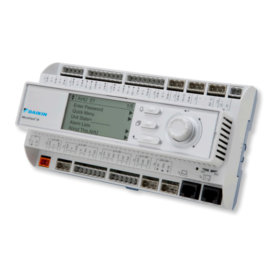
sIng The eypad Isplay sIng The eypad Isplay The keypad/display consists of a 5-line by 22 character display, The keypad/display Information is organized into Menu groups; three keys and a “push and roll” navigation wheel . There is an Main Menu, Quick Menu, View/Set Unit Menu, Commission Alarm Button, Menu (Home) Button, and a Back Button . -
Page 6: Passwords
sIng The eypad Isplay Passwords Various menu functions are accessible or inaccessible, Entering an invalid password has the same effect as continuing depending on the access level of the user, and the password without entering a password . Once a valid password has been they enter, if any . -
Page 7: Service Timers
sIng The eypad Isplay Service Timers Manual Control A user may override timers for a period of up to 240 minutes A user may manually control outputs to check operation of by setting the Service Timer to a non-zero number . When the components when Manual Control is set to ManCtrl . -
Page 8: Keypad/Display Menu Structure
Isplay TruCTure The following is a description of the MicroTech III menu structure . These menus and items can all be displayed with the keypad/ display. Menu items displayed will change based on the selected unit configuration. Figure 4: Main Menu – Keypad/Display Menu Structure See page 6 See page 21 –... - Page 9 eypad Isplay TruCTure See page 33 – 58 See page 59 – 61 See page 62 – 68 See page 74 – 77 See page 69 Commission Unit Manual Control Service Menus Trending Unit Maintenance ► ► Unit Set-Up Manual Control= Normal CFan Outpt 1= Off Timer Settings Trending Ena= No...
- Page 10 eypad Isplay TruCTure Figure 5: View/Set Unit – Keypad/Display Menu Structure See page 23 – 32 View/Set Unit ► Unit Status/Settings ► Occupancy ► Temperatures ► Flow Status ► SAF Spd Control ► RF/EF Control ► Cooling ► Economizer ► Min OA Damper ►...
- Page 11 eypad Isplay TruCTure See page 28 and See page 29 See page 30 and See page 31 and 93 See page 28 and 41 44 – 45 See page 29 and 46 and 46 – 48 51 – 52 – 96 Cooling Economizer Min OA Damper...
- Page 12 eypad Isplay TruCTure Figure 6: Commission Unit – Keypad/Display Menu Structure See page 33 – 58 Commission Unit ► Unit Set-Up ► Timer Settings ► SAF Set-Up ► RF/EF Set-Up ► Htg/Clg ChgOvr Set-Up ► Cooling Set-Up ► INV Cmp Set-Up ►...
- Page 13 eypad Isplay TruCTure See page 41 See page 28 and 38 – 39 See page 40 RF/EF Set-Up Htg/Clg ChgOvr Set-Up Cooling Set-Up Clg Stage Time= 5min RF/EF Ctrl= Tracking MinExStrtTm= 120s Ctlr Temp Src= RAT Rem RAF Cap= 5% MinExStopTm= 120s AplyTstatchg= No Clg DB= 2 .0°F...
- Page 14 eypad Isplay TruCTure Figure 6 continued: Commission Unit – Keypad/Display Menu Structure See page 33 – 58 Commission Unit ► Unit Set-Up ► Timer Settings See page 29 and ► SAF Set-Up ► 49 – 50 RF/EF Set-Up ► Heating Set-Up OA Fan Set-Up Exp Valve Set-Up Htg/Clg ChgOvr Set-Up...
- Page 15 eypad Isplay TruCTure See page 30 and 51 – 52 See page 53 – 54 See page 55 Defrost Set-Up Dehum Set-Up Energy Rec Set-Up Head Pressure Set-Up Defrost State= _________ Dehum Method= None Energy Rcvy= Yes Wtr Reg Vlv= XXX% RH DB= 2% Manual DF= No ER Wheel= ___________...
- Page 16 eypad Isplay TruCTure Figure 7: Service Menu – Keypad/Display Menu Structure See page 62 – 68 Service Menus ► Timer Settings ► Operating Hours ► Save/Restore Settings ► Active Alarms ► Alarm Log ► Alarm Configuration ► Analog Input Status ►...
- Page 17 eypad Isplay TruCTure See page 63 See page 57 Alarm Log Alarm Configuration ► Log Count: xx Clr Log= No ALARM LIMITS page 19 ► 3, 4 See connection on +/-Alarm 1: Alarm Type Hi Disch Temp= 170°F ► +/-Alarm 2: Alarm Type Lo Disch Temp= 40°F ●...
- Page 18 eypad Isplay TruCTure Figure 7 continued: Service Menu – Keypad/Display Menu Structure See page 62 – 68 Service Menus ► Timer Settings ► Operating Hours ► Save/Restore Settings ► Active Alarms ► Alarm Log ► Alarm Configuration ► Analog Input Status ►...
- Page 19 eypad Isplay TruCTure See page 73 See page 62 See page 63 Alarm Lists Active Alarms Alarm Log Alarm Details ► ► Active Alarms Alm Count: xx Clr Alms= No Log Count: xx Clr Log= No +/-Alarm 1: Alarm Type ►...
- Page 20 eypad Isplay TruCTure Figure 8: BMS Communications – Keypad/Display Menu Structure See page 70 BMS Communications ► LON Set-Up ► BACnet MSTP Set-Up ► BACnet IP Set-Up ► D-Net Set-Up ► Network Unit Set-Up IM 918 IM 917 IM 916 See page 70 LON Set-Up BACnet MSTP Set-Up...
-
Page 21: Menu Descriptions
esCrIpTIons esCrIpTIons Quick Menu Items in the Quick Menu contain basic unit operating status and control set point parameters . The items shown in the Quick Menu are Read Only if a valid password has not been entered . The following are brief descriptions of the Quick Menu items . No password is required to view the Quick Menu . - Page 22 esCrIpTIons Unit State is a status only item which indicates the state of DAT Htg Spt is a status only item which indicates the operation in which the unit is currently operating . The unit can temperature that the DAT should be maintained at when in the be in any of the operating states shown .
-
Page 23: View/Set Unit Menus
esCrIpTIons View/Set Unit Menus Unit Status Settings The “Unit Status Settings” menu provides a summary of basic unit status and control items . This menu summarizes the current operating state of the unit, giving the operating state the unit is in, along with the current capacity level of that operating state . - Page 24 esCrIpTIons Unit State is a status only item which indicates the state of Htg Capacity is a status only item which indicates the operation in which the unit is currently operating . The unit can percentage of the unit maximum heating capacity currently be in any of the operating states shown .
-
Page 25: Occupancy
esCrIpTIons Occupancy Menus in the Occupancy menu contain status and control items that relate to unit occupied/unoccupied operation . Table 3: Occupancy Menu Item Display Name Default Setting Range Password Level Occupancy= Unocc TntOvrd Unocc Occ Mode= Auto/Net TntOvrd Auto/Net None NetSchd IntSchd... -
Page 26: Temperatures
esCrIpTIons Temperatures Menus in the Temperatures menu contain unit temperature status information . Table 4: Temperature Menu Item Display Name Default Setting Range Password Level Control Temp= — -50 .0–200 .0°F Disch Air= — -50 .0–250 .0°F Return Air= — -20 .0–200 .0°F Space Temp= —... -
Page 27: Flow Status
“Field Wiring” in the binary input delivered to the controller by a differential pressure MicroTech III Installation Manual (IM 919) . The Pump Start switch (PC7) . On VAV units duct static pressure is also a factor Output is turned on whenever the economizer bypass valve in the indication of airflow. -
Page 28: Rf/Ef Control
esCrIpTIons RF/EF Control Table 7: Return/Exhaust Fan Speed Menu Item Display Name Default Setting Range Password Level RF/EF Speed= 0–100% Speed Cmd= 0–100% Bldg Press= -0 .25–0 .25 in BldgSP Spt= 0 .050 in -0 .25–0 .25 in RF/EF Speed is a status only item that indicates the current BldgSP Spt is an adjustable item which sets the building static return/exhaust fan VFD speed . -
Page 29: Min Oa Damper
esCrIpTIons Min OA Damper Table 10: Min OA Damper Menu Item Display Name Default Setting Range Password Level Min OA Pos= 0–100% Vent Limit= 0–100% LoFlo V Lmt= 0–100% DCV Limit= 0–100% VentLmt DesFlw FldFlw Network Ext VDC Min OA SCR= —... -
Page 30: Dehumidification
esCrIpTIons Dehumidification Table 12: Dehumidification Menu Item Display Name Default Setting Range Password Level Disabled Dehum Status= — Enabled Rel Humidity= — 0–100% Dewpoint= — -50–150°F None None Dehum Method= Rel Hum Always DewPt RH Setpoint= 0–100% Dewpoint Spt= 50°F 0–100°F Reheat Spt= —... -
Page 31: Date/Time/Schedules
esCrIpTIons Date/Time/Schedules Time/Date Table 13: Time/Date Item Display Name Default Setting Range Password Level Time= HH:MM:SS Date= MM/DD/YYYY UTC Diff= Time is an adjustable item that sets the current time. UTC Diff is an adjustable parameter that can be set to indicate how the local time where the unit is situated differs from the Date is an adjustable item that sets the current date. - Page 32 esCrIpTIons One Event Schedule Menu The One Event Schedule is used to set the start and stop times for one event . Table 16: One Event Schedule Menu Item Display Name Default Setting Range Password Level Beg= MMMDD/99 @ HH:MM 00/00/00-12/31/99 @ 00:00 –...
-
Page 33: Commission Unit
esCrIpTIons Commission Unit Unit Setup Table 19: Unit Setup Menu Item Display Name Default Setting Range Password Level Apply Changes= No, Yes RAT Sensor= No, Yes OAT Sensor= No, Yes None Space Sensor Digtl/Net Anlog/Net Digtl/Net Eng Units= English English, SI Unit Name= —... - Page 34 esCrIpTIons Service Time is an adjustable item that sets the amount of Clg Stg Time is an adjustable item used to set a minimum time time the internal control timers can be temporarily sped up . period between compressor stage changes . Startup is an adjustable item that sets the time in seconds that Htg Stg Time is an adjustable item used to set a minimum the unit will perform its startup operation .
-
Page 35: Saf Set-Up
esCrIpTIons SAF Set-up Table 21: Supply Fan Speed Menu Item Display Name Default Setting Range Password Level Item Display Name Default Setting Range Password Level CONTROL Spd/Net Min PPM= 0ppm 0–5000ppm 1ZnVAV Max PPM= 2000ppm 0–5000ppm SAF Ctrl= V/A @ Min PPM= 0 .0/V 0 .0–20 .0/V/mA V/A @ Max PPM=... - Page 36 esCrIpTIons BSP Input is an adjustable item used to select whether on Min Htg Spd is an adjustable item that sets the minimum not a building static pressure sensor is connected to the unit supply fan speed used for heating operation when 1ZnVAV is controller .
- Page 37 esCrIpTIons Min CFM is an adjustable item that sets the minimum CFM DSP Ctrl Dly is an adjustable item that sets the duration of value of the field supplied airflow station input signal. time that the minimum speed signal is sent to the variable speed supply air fan after the supply fan is started via a digital Max CFM is an adjustable item that sets the maximum CFM output .
-
Page 38: Rf/Ef Set-Up
esCrIpTIons RF/EF Set-Up Table 22: Return Fan/Exhaust Fan Set-up Menu Item Display Name Default Setting Range Password Level None Tracking RF/EF Ctrl= Tracking BldgP Spd/Net OA Damper Rem RAF Cap= 0-100% Rem ExhF Cap= 0-100% BSP DB= 0 .01in 0 .0-0 .1in BSP Period= 0-999s BSP Gain=... - Page 39 esCrIpTIons RF/EF Ctrl is an adjustable parameter used to select how the RFEF Ctrl Delay is an adjustable item that sets the duration return/exhaust fans are to be controlled . The exhaust fans of time that the minimum speed signal is sent to the variable can be controlled by the building pressure or by a percentage speed supply air fan after the return fan is started via a of return/exhaust air fan speed from 5% to 100% .
-
Page 40: Heat/Cool Changeover Set-Up
esCrIpTIons Heat/Cool Changeover Set-Up Table 23: Heat/Cool Changeover Setup Menu Item Display Name Default Setting Range Password Level Space Ctrl Temp Src= None Use Tstat Spt= No, Yes Occ Clg DB= 2 .0°F 0 .0–10 .0°F Clg Period= 0–999s Clg Gain= 0 .1 0 .0–100 .0 Clg PAT=... -
Page 41: Cooling Set-Up
esCrIpTIons Cooling Set-Up Table 24: Cooling Set-up Menu Item Display Name Default Setting Range Password Level Clg Stage Time= 5min 5–60min Clg DB= 2 .0°F 1 .0–10 .0°F Clg Lo OAT Lk= 55°F 0–100°F OAT Diff= 2°F 0–10°F None Ntwrk Space Return Clg Reset=... -
Page 42: Variable Compressor Set-Up
esCrIpTIons Variable Compressor Set-up Table 25: Variable Compresor Setup Menu Item Display Name Default Setting Range Password Level Compressor Status Var Cmp Status= — Var Spd Cmd= — 0–100% Comp 1= — Comp 3= — Comp 5= — Refrig Circuit Status PTD1= —... - Page 43 esCrIpTIons Var Cmp Status is a status only item that indicates whether VarCmp Period is an adjustable item that sets the sample variable speed compressor on circuit # 2 is ON or OFF . period for the PI loop used to control the variable speed compressor capacity to maintain the effective discharge air Var Spd Cmd is a status only item that indicates the current temperature setpoint .
-
Page 44: Econo Set-Up
esCrIpTIons Figure 10 graphically shows the cooling reset operation . The Unocc Diff is an adjustable item that sets the unoccupied normal DAT cooling set point is 55 .0 F . The cooling reset cooling differential . scheme is set to airflow. The unit is to adjust the DAT from 55.0 F to 65.0 F. - Page 45 esCrIpTIons EconChangover is an adjustable item used to set how Max Clg Spt is an adjustable item which sets the maximum economizer operation will be enabled cooling discharge set point for use with a cooling discharge air temperature set point reset schedule . Econo FDD is an adjustable item used to enable or disable the Economizer Fault Detection and Diagnostics function Max Clg Spt @ is an adjustable item which sets the value of...
-
Page 46: Min Oa Set-Up
esCrIpTIons Min OA Set-Up Table 27: Min OA Damper Menu Item Display Name Default Setting Range Password Level Apply Changes No, Yes None Network Ext VDC Min OA Reset= None Ext mA IAQ VDC IAQ mA BSP OA Ovrd No/Yes None Rst Lmt Snsr None... - Page 47 esCrIpTIons Apply Changes - the Apply Changes flag must be changed Min PPM is an adjustable item that sets the minimum PPM from no to yes in order for the controller to recognize value . the changes. Setting the Apply Changes flag to YES will Max PPM is an adjustable item that sets the maximum PPM automatically reset the controller .
- Page 48 esCrIpTIons OA Flow is a status only item which indicates the current BSPOvdST an adjustable item which sets the “sampling time” outdoor airflow based on an optional OA airflow sensor input used in the PI control function used for the building static used when the unit is equipped the DesignFlow OA control pressure override feature .
-
Page 49: Heating Set-Up
esCrIpTIons Heating Set-Up The Heating menu provides a summary of the control The control temperature can be return temperature, space parameters for units with heating . The unit’s heating mode temperature or outside air temperature . The unit goes into the of operation is controlled by the control temperature and the heating mode of operation when the control temperature is heating setpoint temperature . - Page 50 esCrIpTIons Htg Stage Time is an adjustable item used to set a minimum Min DAT Limit is a status only item which indicates the time period between heating stage changes . discharge air low limit temperature on CAV zone control units .
-
Page 51: Dehum Set-Up
esCrIpTIons Dehum Set-Up Table 29: Dehumidification Menu Item Display Name Default Setting Range Password Level None Rel Hum Dehum Method= None DewPt Always RH DB= 0–10% Dewpoint DB= 2 .0°F 2–10°F RH Period= 0–999s RH Gain= 0 .0–100 .0 RH PAT= 0–999s RH Max Chg= 0–100%... - Page 52 esCrIpTIons Dehum Method is an adjustable item used to set the Sensor Loc is an adjustable item which is used to select the dehumidification method to either “RH” or “DewPt.” When location of the humidity sensor . The location is selected by this parameter is set to “RH,”...
-
Page 53: Energy Recovery Set-Up
esCrIpTIons Energy Recovery Set-up The Energy Recovery Set-up menu contains parameters that relate to or are used to control the enthalpy wheel and exhaust fan when a unit is equipped with an optional energy recovery wheel system . Table 30: Energy Recovery Item Display Name Default Setting Range... - Page 54 esCrIpTIons Energy Rvcy is an adjustable item which turns the optional Rel Humidity is a status only item that indicates the current energy recovery system ON /OFF . relative humidity reading of the sensor . ER Wheel is a status only item used to indicate whether the Min Whl Spd is an adjustable item used to set the energy energy recovery wheel is currently ON or OFF .
-
Page 55: Head Pressure Set-Up
esCrIpTIons Head Pressure Set-Up The Head Pressure Set-Up menu contains parameters that are used to maintain head pressure control . Table 31: Head Pressure Setup Menu Item Display Name Default Setting Range Password Level Wtr Reg Vlv= — 0–100% Head P Circ 1= —... -
Page 56: Evap Cond Set-Up
esCrIpTIons Evap Cond Set-Up Table 32: Evap Condensing Menu Item Display Name Default Setting Range Password Level Cond Fan Spd= — 0–100% CFan Spd Cmd= — 0–100% Min Fan Speed= 0–100% EvCond Stg Tm= 10min 0–100min Sump Temp= — -50 .0–150 .0°F Min Sump T= 75 .0°F 0 .0–100 .0°F... -
Page 57: Alarm Configuration
esCrIpTIons Alarm Configuration Alarm Limits Menu The Alarm Limits menu is used to set the limits of the discharge air temperature sensor and the return air temperature sensor . Table 33: Alarm Limits Setup Menu Item Display Name Default Setting Range Password Level Hi Disch Temp=... -
Page 58: Alarm Delays Menu
esCrIpTIons Alarm Delays Menu The Alarm Delays Setup Menu can be accessed when a level 2 password has been entered . The default settings are the result of many years of testing and should not be changed . Table 35: Alarm Delays Setup Menu Item Display Name Default Setting Range... -
Page 59: Manual Control
esCrIpTIons Manual Control The manual control of operation is a function that is used for operating the unit during a service call only . The unit must not be operated in this mode for any extended period of time . Table 36: Manual Control Menu Item Display Name Default Setting... - Page 60 esCrIpTIons Table 36 continued: Manual Control Menu Item Display Name Default Setting Range Password Level GasHtg OnOff= Htg Valve= 0–100% SCR Out= 0–100% F&BP Damper= 0–100% Htg Stg 1= SCR Ena 1= Htg Stg 2= SCR Ena 2= Htg Stg 3= Htg Stg 4= Htg Stg 5= Htg Stg 6=...
- Page 61 esCrIpTIons U1 Comp 1 is an adjustable item the turns ON unloader 1 on Htg Valve is an adjustable item used to manually drive the compressor 1 . modulating heating valve open and closed . U1 Comp 2 is an adjustable item the turns ON unloader 1 on SCR Out is an adjustable item used to manually drive the compressor 2 .
-
Page 62: Service Menus
esCrIpTIons Service Menus Timer Settings Menu The Timer Settings Menu is also available from the Commission Unit Menu, and is described on page 33 Save/Restore Menu The Save/Restore menu can be used to save or restore the user configured parameters as well as reset the controller back to the factory default parameters . - Page 63 esCrIpTIons Alarm Log Menu The last fifty alarm events (alarm detection and return to normal) as well as the date and times that they were detected are displayed on the Alarm Log menu . These alarm events are displayed in the order that they were detected . The alarm event that was detected most recently is displayed first.
- Page 64 esCrIpTIons Universal I/O Status Menu The Universal I/O Status Menu provides diagnostic information configured for mA, the value will be displayed in micro amps to qualified service personnel. The items listed in this menu (1 mA = 1000 micro amps). If I/O is configured for voltage, the will provide current status information of the Universal inputs value is displayed in 1/1000th volt scale .
- Page 65 esCrIpTIons Digital Input Status Menu The Digital Input Status Menu provides diagnostic information to qualified service personnel. The items listed in this menu will provide current status information of the controller’s digital inputs . Table 42: Digital Input Status Menu Item Display Name Default Setting Range...
- Page 66 esCrIpTIons Network Input Status Menu The Network Input Status Menu provides diagnostic information to qualified service personnel. The items listed in this menu will provide current status information of the controller’s network inputs . Table 44: Network Input Status Menu Range Range Default...
-
Page 67: Modbus Status Menu
esCrIpTIons Modbus Status Menu The Modbus Status Menu provides diagnostic information to qualified service personnel. The items listed provide the status of the Modbus communications with the various devices controlled by the internal Modbus network Table 45: Modbus Status Menu Item Display Name Default Setting Range... -
Page 68: Sensor Offsets Menu
esCrIpTIons Sensor Offsets Menu The Sensor Offsets Menu provides a means of calibrating the various temperature sensor inputs to the unit . Each sensor can be “biased” by as much as +/- 10 .0°F . Table 47: Sensor Offset Menu Item Display Name Default Setting Range... -
Page 69: Unit Maintenance
esCrIpTIons Unit Maintenance Operating Hours The Operating Hours menu gives a summary of the hours of operation for each of the supply fans, return/exhaust fans, compressors, heating and economizer operation . Table 48: Operating Hours Menu Item Display Name Default Setting Range Password Level Supply Fan=... -
Page 70: Bms Communications Menu
BMS Communications Menu LON/BACnetIP/BACnetMSTP Setup Menu See the Installation & Maintenance Manuals below for detailed • IM 916 MicroTech III Rooftop unit controller - BACnet IP instructions communications • IM 917 MicroTech III Rooftop unit controller - BACnet MSTP communications •... -
Page 71: Unit Configuration
esCrIpTIons Unit Configuration Unit Configuration Setup Menu After the main control board application software is loaded the control panel door . into the MCB, it must be “configured” for the specific Table 50 lists the configuration code variables including the control application . - Page 72 esCrIpTIons Table 50 continued: Unit Configuration Menu Configuration Description Values (Default in Bold) Special Condition DPS_H Code Position 1 – 8 Stages (default = 8)/ 0=NA 1=Single Generic Condenser Stages/ ● ● ● VFD Comp Cfg (if 4=4, 5or 6) (if 4=4, 5or 6) 2=Tandom 3=Trio...
- Page 73 esCrIpTIons Table 50 continued: Unit Configuration Menu Configuration Description Values (Default in Bold) Special Condition DPS_H Code Position 0=None 1=Tracking Return/Exhaust Fan Capacity 2=Building Pressure ● ● ● ● Control Method 3=Speed 4=OADamper 0=No Second Duct Pressure Sensor ● ● 1= Yes 0=No Entering Fan Temp Sensor...
-
Page 74: Trending Menus
esCrIpTIons Trending Menus The Trending Menus allow for setting up and managing onboard Points 1-8 (Fixed) trending of up to 30 data points within the controller . This data The first 8 trending points are fixed and will automatically be trended can then be exported to an SD card . -
Page 75: Points 25-27 (With Ids)
esCrIpTIons Points 25-27 (With IDs) Points 28-30 (With IDs) Trending Points 25 through 27 can be freely selected all Trending Points 28 through 30 can be freely selected all the available points and point members that exist within the the available points and point members that exist within the controller . -
Page 76: Trending Selection Lists
esCrIpTIons Trending Selection Lists Table 56: Primary Trending Select List HMI Name Select Abbreviation Type Bldg Press= 2203 F0AFC4BB Clg State= ClgSt 230B F0AF3991 Clg Status= ClgSts 230B F0AFF6A6 Clg Press Lmtg= ClPLmtg 230B F0AF3B4E Cmp Ratio Lmtg= CpRLmtg 230B F0AF7BA2 DAT Clg Spt= DAClgSp... - Page 77 esCrIpTIons Table 57: Secondary Trending Select List HMI Name Select Abbreviation Type Alarm Enumeration 230A F0AFCF76 IAQ PPM= 2203 F0AF7F77 Cmp Ratio Lmtg= CpRLmtg 230B F0AF7BA2 DAT Htg Spt= DAHtgSp 2300 F0AF6054 Dewpoint= Dewpt 230A F0AF532C Dewpoint Spt= DewptSp 2300 F0AF75C1 Defrost State= DFSt...
-
Page 78: Alarms
larMs larMs About this Unit Table 58: About this Unit Menu Faults are conditions that are serious enough to shut down the unit . The alarm must be manually cleared to allow unit Menu Display Name Item Display Name operation . SO_Item= Unit SN= Problems are conditions that result in some limitation of unit... -
Page 79: Warnings
larMs Warnings Over Economizing The under economizing alarm will also be generated when the OAT sensor is unreliable or the RAT sensor is unreliable while A warning alarm indicating the unit is economizing when it the OAT is below the Min OAT Limit setting (default 70F) and should not be will be generated whenever the outdoor air the economizer changeover method (EconChgovr) is set for dampers are stuck open while operating in the Econo or... - Page 80 larMs OAD Stuck Dirty Filter - (Dirty Filter: Warning) A warning alarm indicating the outdoor air dampers are stuck If the pressure drop across the filter section in the unit and not modulating will be generated whenever the damper exceeds the setting of the differential pressure switch the are stuck open or stuck closed .
-
Page 81: Problems
larMs Problems Hi DL Temp: Problem Low Discharge Superheat: Problem Normal compressor control is limited when a high discharge Normal compressor control is limited when low superheat line temperature conditions occur . If the variable speed conditions occur . If the variable speed compressor is operating compressor is operating and the discharge line temperature and the discharge superheat is less than 20F continuously is greater than 250F for 15 seconds a High Discharge Line... - Page 82 larMs Variable Compressor Oil: Problem No Water Flow Problem - (Water Flw Sw: Problem) (Self Contained only) If the variable speed compressor has been operating at the High When a unit is equipped with a water flow switch WFS, the No Oil Boost value for the Oil Boost Timing period and the low oil Water Flow problem occurs when lack of water flow is indicated input (EMC-X3) is still open the variable speed compressor is...
- Page 83 larMs High Pressure - Circuit 1, 2, 3, 4, 5, 6 - (Hi Press 1, 2, Space Temperature Sensor Problem - (Space 3, 4, 5, 6: Problem) Sensor: Problem) This alarm occurs on units equipped with compressorized If the Space Sensor Present setting is set to Yes, a valid Space cooling only .
-
Page 84: Faults
Heat Fail Problem - (Heat Fail: Problem) when a unit has a CAV supply fan . If an RPS unit is equipped with a Daikin gas furnace and If Modbus communication is lost between the MCB the burner flame safeguard (FSG) control enters the “safety and the supply fan VFD the duct static pressure is not lockout”... - Page 85 larMs High Return Air Temperature - (Hi Return Tmp: Fault) Emergency Stop Fault - (Emerg Stop: Fault) If the return air temperature is greater than the Return Air An Emergency Stop Fault will occur if either of the following Temperature Limit (Default = 120°F) and the supply fan has conditions is true: been on for longer than the temperature alarm delay (Default •...
-
Page 86: Operator's Guide
The following “Operator’s Guide” sections provide information The supply fan is turned ON when the unit enters the regarding the day-to-day operation of the MicroTech III Recirculation state . The supply fan in VAV units is controlled as Unit Controller . Topics covered are such common tasks as... -
Page 87: Recirculating Operating State
’ peraTor uIde Recirculating Operating State Heating Units with return air always enter the Recirculating operating The unit enters the Heating operating state when the control state after the completion of the Startup operating state . temperature falls below the Occupied or Unoccupied Heating In the Recirculating operating state fans are started and Setpoint by more than ½... -
Page 88: Mechanical Cooling
’ peraTor uIde Mechanical Cooling Off Alarm The unit operating state is OFF and the unit status is OffAlm The unit enters the mechanical cooling operating state when when an active alarm of the “fault” type has the unit shutdown . cooling is required and the economizer is disabled, not present, or already fully open . -
Page 89: Determining Cooling Status
’ peraTor uIde Determining Cooling Status Determining Heat Status Clg Status is a status item which indicates whether or not Htg Status is a status item which indicates whether or not mechanical cooling is currently allowed . If cooling is disabled, heating is currently allowed . -
Page 90: Determining Economizer Status
’ peraTor uIde Determining Economizer Status Determining Cooling Capacity If the unit is equipped with a 0-100% modulating economizer Clg Capacity is a status item which indicates the percentage (waterside or airside) and the conditions are suitable for free of the unit maximum cooling capacity currently operating . cooling, the unit attempts to satisfy the cooling load by using When the unit is equipped with chilled water cooling, 0-100% either outdoor air or the waterside economizer before using... - Page 91 ’ peraTor uIde Determining Application Mode Determining Occupancy Status The unit heating and cooling can be set up for automatic Occupancy is a status item which indicates whether the unit heat/cool, heat only, cool only or fan only operation based is in an occupied, unoccupied or tenant override mode of on a network signal by setting the Control Mode parameter operation .
-
Page 92: Determining Occupancy Mode
’ peraTor uIde Determining Occupancy Source Tenant override operation is initiated when the Tenant Override Timer is greater than zero . The Tenant Override Timer is set When the Occupancy parameter indicates Occ, the occupancy equal to the Local Tenant Override Time (Timer Settings menu) source is set to one of the following values to indicate the if the unit is enabled and any of the following is true: function responsible for placing the unit into the occupied mode... -
Page 93: Unoccupied Operation
’ peraTor uIde Unoccupied Operation Scheduling During unoccupied operation the unit operates normally except The Air Handling unit can be scheduled for operation by using that Min OA Pos is set to zero so that the damper is closed to the following three methods: the outdoor air . -
Page 94: Temperature Control Configurations
’ peraTor uIde Temperature Control Configurations One Event Scheduling A One-Event Schedule is provided so that one operating Temperature control is based on a Control Type that may be period can be scheduled without affecting the regular internal set to Zone, DAT, or Single Zone VAV . schedule . -
Page 95: Control Temperature
’ peraTor uIde Illustrative Heat/Cool Changeover Sequence The Control Temperature Source automatically reverts from Return to Space if both of the following are true: The following is an illustration of the heat/cool changeover • The Return Air Sensor is not present and reliable function . - Page 96 ’ peraTor uIde OA/EWT Lockout Zero OA Time (Morning Warm-up) Heating is disabled whenever the outdoor air temperature A separate Morning Warm-up operating state is not provided, is greater than the Outdoor Air Ambient Heating Lockout but an editable ZeroOATime is used to keep the Outside Air Set Point .
-
Page 97: Dehumidification
’ peraTor uIde Dehumidification Dehumidification Mechanical Cooling Control During dehumidification, control of mechanical cooling is In the dehumidification mode, mechanical cooling is used to based on the following two editable values of the Leaving Coil cool air low enough to wring moisture out of it . Hot Gas Reheat Temperature setpoint . - Page 98 ’ peraTor uIde Dehumidification Reheat Control Modulating HGRH Control During dehumidification control either an analog or digital In the Cooling and Fan Only states, a PI Loop is used Hot Gas Reheat (HGRH) output or the standard modulating to control the HGRH valve to maintain the discharge air heating output is controlled to maintain the current Reheat temperature at the Dehumidification Reheat Setpoint.
-
Page 99: Energy Recovery
’ peraTor uIde Energy Recovery Enthalpy Wheel Frost Prevention Energy recovery is provided by drawing outside air across half of an enthalpy wheel and drawing exhaust air across the other Two different frost protection methods are provided depending half . Latent and sensible heat is transferred from the hotter, on whether or not the enthalpy wheel is controlled by a VFD . - Page 100 ’ peraTor uIde Constant Speed Wheel Frost Prevention Control Enthalpy Wheel Defrost Control (Constant Speed Wheels Only) The enthalpy wheel is stopped when both of the following are In lieu of the frost prevention method described above, a true: constant speed enthalpy wheel can be set for a simpler •...
- Page 101 ’ peraTor uIde Heating All four of the following are true: When the unit is operating in the Heating state, the energy • The exhaust fan is controlled by a VFD recovery wheel is stopped due to capacity limiting whenever •...
-
Page 102: Outside Air Damper Control
’ peraTor uIde Bypass Dampers (Not Applicable for 100% OA Figure 14: Damper Position versus Fan Speed Chart Units) The bypass dampers are driven closed (Bypass Damper Closed output is energized) whenever the OA Damper position is less than or equal to the Minimum OA Position The Bypass dampers are driven open (Bypass Damper Open output is energized) whenever the OA Damper Position exceeds the Minimum OA Damper Position by more that 3%... - Page 103 ’ peraTor uIde Minimum Outside Air Reset - None Example #1 Min OA reset type = IAQ VDC If None is selected as the Min OA Reset Type, the Minimum If the requirement is to have the OA damper be at its minimum OA Position is set equal to the Ventilation Limit .
- Page 104 ’ peraTor uIde Reset Temperature Limit NOTE: The factory default for Min OA Reset is set to none however changes may be made by accessing the Min The user has the option of setting a low temperature limit that OA Set-Up menu . Once changes have been made to will override all the outdoor air reset functions described in this the Min OA Reset type, the Apply Changes flag must section except the Return Fan Capacity Override function if the...
-
Page 105: 100% Outside Air Damper Control
’ peraTor uIde Airside Economizer Table 50: Outdoor Air Damper Minimum Position Reset Schedule If a unit is equipped with a 0-100% modulating economizer, and the outdoor air is suitable for free cooling, the unit attempts Discharge Fan <= 20% Min Fan Between Min and >= 50% Max Fan Speed –... - Page 106 ’ peraTor uIde OAD End Switch Calibration The outdoor air damper end switch input requires a calibration When the CalibrateOAD parameter is set from No to Yes the function that captures the command position at which the following sequence occurs: switches open and close at the closed and open ends of the Step 1: The damper command is increased 1% every 2 damper modulation range .
-
Page 107: Bypass Valve Control
’ peraTor uIde Bypass Valve Control This section describes the operation of an analog output used When the Bypass Valve is open, all water that flows into the to control a valve that allows water to bypass a waterside self-contained unit flows directly to the condenser without any economizer and flow directly into a condenser. -
Page 108: Water Pump Control
’ peraTor uIde Water Pump Control In the Economizer state, the Water Regulating Valve is normally closed . The WRV Start Sequence described below The Pump output is in the on position if any of the following is initiated in the Economizer state whenever either of the are true: following is true: •... - Page 109 ’ peraTor uIde If the Discharge Air Temperature exceeds Discharge Cooling If the last stage change was a stage up and the stage Setpoint, the difference is added to the Degree Time Above decreases due to the Degree Time Below exceeding the value .
- Page 110 ’ peraTor uIde Point 5 The Cooling Interstage Timer has expired . The Point 7 The discharge air temperature is again above the discharge air temperature is above the Effective Discharge Effective Discharge Cooling Set Point by more than half the Cooling Set Point by more than half the Discharge Cooling Dead Discharge Cooling Dead Band .
-
Page 111: Cooling: Modulating
’ peraTor uIde Staging - Zone Control Project Ahead In the Cooling state, compressor stages are turned ON and This section describes the Projected Control Temperature OFF to maintain the control temperature close to the Occupied used to turn on and off stages of heating and cooling for Zone or Unoccupied Cooling Setpoint. -
Page 112: Reset - Cooling
’ peraTor uIde Discharge Air Temperature Setpoint Reset - Cooling The Cooling DAT Setpoint may be reset for units with DAT When Airflow is selected, the values “Min Clg Spt @” and Cooling Control . The reset type may be set to one of the “Max Clg Spt @”... -
Page 113: Compressor Control For Roofpak
’ peraTor uIde Compressor Control for RoofPak VFD Compressor Operation When an RTU is equipped with the VFD compressor option between 25rps (0VDC) and 100rps (10VDC) . The minimum there are two compressor circuits, one VFD controlled and maximum rps (VDC) values actually used vary depending compressor in circuit #2 with up to 3 fixed speed compressors on unit size, whether or not a fixed speed compressor is in circuit #1 depending on unit model . - Page 114 . The low oil condition is VFD compressor are stopped first). The VFD compressor is communicated to the MicroTech III controller via a digital input held at its maximum value for 30 seconds (EMC-X3) signal from the VFD compressor .
- Page 115 High Discharge Line Temperature Unloading Control a solenoid valve on each circuit controlled by a normally open digital output (EMC DO1, EMC-DO2) from the MicroTech III Normal compressor control is limited when a high discharge controller . The coil splitter solenoid valve is controlled based line temperature conditions occur .
- Page 116 ’ peraTor uIde Network Load Shed Control Heating Operation For Zone Control or Single Zone VAV units a network variable When DemandShed= is set to Enabled and the Network is provided to allow for overriding the current occupied cooling variable parameter is set to Active the current Occupied and occupied heating setpoints by an adjustable increment.
-
Page 117: Compressor Control For Maverick Ii
’ peraTor uIde Compressor Control for Maverick II VFD Compressor Operation When a MPS is equipped with the VFD compressor option VFD compressor modulation is additionally monitored and there are two refrigeration circuits, one VFD controlled adjusted in order to maintain operation within the approved compressor with up to 3 fixed speed compressors depending compressor operating envelope . - Page 118 ’ peraTor uIde VFD Compressor Control Dehumidification Transition During Cooling State Control of the VFD compressor is accomplished with a digital When dehumidification operation becomes active while the output enable signal and a 0-10VDC analog modulating unit is in the Cooling operating state, The VFD compressor control signal .
- Page 119 ’ peraTor uIde If the oil balance mode fails to resolve the low oil condition, VFD Compressor Protection Unloading Control or the fixed speed compressor was not running when the low There are several modulating control functions that adjust the oil indication occurred, or the VFD compressor was not part speed control range of the VFD compressor to protect it from of a tandemized compressor set, when the low oil indication...
- Page 120 ’ peraTor uIde High Superheat High Discharge Line Temperature Unloading Control A compressor discharge temperature sensor (Thermistor) is If the VFD compressor discharge superheat rises to 75F for 10 installed on the VFD compressor as standard . The temperature consecutive minutes, the VFD compressor speed is reduced is used to measure discharge temperature and superheat by 10 rps increments down to a 40 rps operating speed .
- Page 121 . A solenoid valve on each circuit is controlled by a output will be turned OFF for 5 seconds and then turned digital output from the MicroTech III controller . ON and ramp VFD compressor speed to 60Hz . If controller...
-
Page 122: Compressor Low Ambient Option
Condenser Fan Operation for Variable Speed Compressor Low Ambient Option (MPS 040 and 050 Only) Daikin’s head pressure control operates by modulating the Figure 19: R-410A Speedtrol motor speed of one condenser fan on the VFD compressor refrigeration circuit in response to the condenser pressure . -
Page 123: Variable Frequency Drive For Vfd Compressor
’ peraTor uIde Variable Frequency Drive for VFD Compressor Basic Operation of Compressor Drive: WARNING Start= Connect terminals 12 & 18 for minimum of 5 secs, Never bypass the compressor drive or directly connect connect terminals 12 &27 and terminals 13 &37 the VFD compressor to the main power supply . -
Page 124: Variable Speed Scroll Compressor
Guidelines . Under all circumstances, the EN378 (or other applicable local safety regulations) requirements must be fulfilled . Daikin units with variable speed inverter compressor are engineered with fixed speed compressor(s) in such a way that the unit delivers only the required energy to satisfy space conditions and provides you with exceptional energy savings . - Page 125 ’ peraTor uIde Oil Injection Control Optical Oil Level Sensor The VFD compressor contains an oil injection valve and An optical oil sensor is used to monitor oil level in VFD solenoid (SV11) as standard. The oil injection valve provides compressor sump.
-
Page 126: Condenser Fan Control
’ peraTor uIde Condenser Fan Control RPS Units There are up to four condenser fans per circuit. The first fan on Condenser Fan Output 2 is turned ON when any each circuit is always turned on when any compressor on the compressor is ON and the OAT rises above the Condenser circuit is turned on through auxiliary switches on the compressor Fan B Set Point . -
Page 127: Mps Standard Condenser Fan Control
’ peraTor uIde MPS Standard Condenser Fan Control Standard Condenser Fan Control Two, three or four condenser fans are provided . Two When the “new” four condenser fan method is used condenser fans are provided on 15, 17 .5, 20 and 25 ton units . (Condenser Control=Standard Method 2), the condenser Three condenser fans are provided on 26, 30 and 35 ton units . - Page 128 ’ peraTor uIde Evaporative Condensing Control (RTU) The evaporative condensing option for rooftop units uses The Staging Type can be set to either Standard or Alternate . the heat absorbed by evaporating water as well as air drawn Standard: across a bank of tubes with refrigerant flowing through them The two circuits are loaded up and unloaded as evenly as to condense hot refrigerant to a liquid .
- Page 129 ’ peraTor uIde Table 60: Dehumidification Staging Two Compressors and Six Stages (CompCfg=4 & Cond Ctrl=2 or 3) Circuit # 1 Circuit # 2 Stage Comp Liq Line Valve Comp # 1 Comp # 1 Comp Liq Line Valve Comp # 2 Comp # 2 Unl # 2 Unl # 1...
- Page 130 Whenever any compressor is turned ON, the lead condenser OFF for normal operation, the output that has been on for the fan on both circuits is turned ON by the Microtech III controller longest period of time is turned OFF .
-
Page 131: Heating Control
’ peraTor uIde Heating Control Entering Heating Operating State Heating: Staged Zone Control The unit enters the Heating operating state from the Fan Only When the unit first enters the Heating operating state the unit operating state when the control temperature falls below the goes directly to Stage # 1 . -
Page 132: Modulating
’ peraTor uIde Modulating RTU Gas Heating When a unit is equipped with modulating gas heating and is Entering Heating Operating State in the Heating operating state, the gas valve is modulated The unit enters the Heating operating state from the Fan Only to maintain the discharge air temperature at the Discharge operating state when the Control Temperature falls below Heating Set Point . - Page 133 ’ peraTor uIde Upon a call for heat, the controller will close digital output Typical Sequence of Operation (3-1 Gas) (EXPB-DO1) and energize the R20A relay . Once the normally When 120V power is furnished through the system ON/OFF open contacts of the R20A relay close 120V power is supplied switch (S1), through the burner ON/OFF switch (S3), and to terminal # 6 on the FSG .
-
Page 134: Mps Gas Heating
’ peraTor uIde Special Start Sequence for 100% Outdoor Air Units The unit remains in either the Heating or Minimum DAT with Gas Heat operating state for the duration of the Hold Period (Default = 240 seconds) . The gas heating valve does not modulate A special start sequence is used for units 100% outdoor air from its calculated value to allow the temperature to approach units with gas heat . - Page 135 ’ peraTor uIde Sequence of Operation (Modulating Burner) Discharge Air Temperature Setpoint Reset - Heating The Heating DAT Setpoint may be reset for units with DAT 5–1 Gas Burner Heating Control . The Discharge Air Temperature Setpoint The following details the sequence of operation for the low will never be set below the Minimum DAT Heating Setpoint heat option .
-
Page 136: Indoor Air Fan - On/Off Control
33%) while the fan is operating . Cooling Set Point varies linearly between the Minimum Discharge Cooling Set Point and Maximum Discharge Cooling NOTE: Units supplied with Daikin MD2, MD3, and MD6 Set Point . This is shown as Point B in Figure 28 . - Page 137 ’ peraTor uIde Cooling/Economizer Carbon Dioxide Control (CO When the Unit State is Cooling or Econo the Single Zone VAV supply fan control is available on 100% OA units that have Control PI_Loop will be set for direct acting control to modulate the Control Type set to Zone or DAC .
- Page 138 SAF capacity control method, the supply fan VFD or ECM motor is controlled with a PI_Loop to maintain the NOTE: Units supplied with Daikin MD2, MD3, and MD6 Control Temperature input at the Occupied Cooling Setpoint drives will have a user editable maximum return fan/ or Occupied Heating Setpoint .
- Page 139 ’ peraTor uIde Exhaust Fan - Speed Control Exhaust Fan - Speed Control The exhaust fan is turned ON when the OA Dampers are When speed control is selected, the fan operates at the larger at least open to the Minimum Exhaust OA Position (default of its minimum speed or a value provided via a connected 5%), the SAF capacity is above the Minimum Exhaust SAF network or the keypad/display .
-
Page 140: Troubleshooting
’ peraTor uIde Troubleshooting Fan Failure Codes HLL = Hall Sensor Error First occurrence: Power fluctuations may be responsible. Corrective: Reset the failure; re-start the motor and observe it. If applicable, filter out the source of the disturbing voltage . Repeated occurrence: Question: Do other fans show the same failure? - Page 141 ’ peraTor uIde TFE = Power Mod Overheated First occurrence: Excessive ambient temperature may be responsible . Question: • Do other fans (temporarily) show the same failure within the arrangement? Could ambient temperature have been too high? Or is the motor overloaded? •...
- Page 142 ’ peraTor uIde PHA = Phase failure UzLow = DC-Link Undervoltage UzHigh = DC-Link Overvoltage UeHigh = Mains Overvoltage UeLow = Mains Undervoltage Question: Can the main voltage be measured at any spot; a data logger may be helpful . No: Measure the voltage at the power supply input of the concerned fan .
- Page 144 Daikin Applied Training and Development Now that you have made an investment in modern, efficient Daikin equipment, its care should be a high priority. For training information on all Daikin HVAC products, please visit us at www.DaikinApplied.com and click on Training, or call 540-248-9646 and ask for the Training Department.
Need help?
Do you have a question about the MicroTech III and is the answer not in the manual?
Questions and answers
clearing faults