Daikin MicroTech III Installation And Maintenance Manual
Chiller unit controller.
models agz and amz trailblazer air-cooled scroll chiller
Hide thumbs
Also See for MicroTech III:
- Operation manuals (144 pages) ,
- Operating manual (77 pages) ,
- Sales and engineering data sheet (68 pages)
Table of Contents
Advertisement
Installation and Maintenance Manual
MicroTech
®
Modbus
Communication Module
®
Models AGZ and AMZ Trailblazer
Models AWS and AWV Pathfinder
Model ADS Air-cooled Global Screw Chiller
Model WME, B Vintage, Magnitude
Model WWV, Navigator
III Chiller Unit Controller
Water-cooled Screw Chiller
®
Air-cooled Scroll Chiller
®
Air-cooled Screw Chiller
®
Magnetic Bearing Centrifugal Chiller
®
IM 969-5
Group: Controls
Part Number: IM 969
Date: January 2018
Advertisement
Table of Contents

Subscribe to Our Youtube Channel
Related Manuals for Daikin MicroTech III


Summary of Contents for Daikin MicroTech III
- Page 1 Installation and Maintenance Manual IM 969-5 Group: Controls Part Number: IM 969 Date: January 2018 MicroTech III Chiller Unit Controller ® Modbus Communication Module ® Models AGZ and AMZ Trailblazer Air-cooled Scroll Chiller ® Models AWS and AWV Pathfinder Air-cooled Screw Chiller ®...
-
Page 2: Table Of Contents
© 2018 Daikin Applied, Minneapolis MN. All rights reserved throughout the world Daikin Applied reserves the right to change any information contained herein without prior notice. The user is responsible for determining whether this product is appropriate for his or her application. -
Page 3: Introduction
Operation of this equipment in a residential area is likely to cause harmful interference in which case the user will be required to correct the interference at his or her own expense. Daikin disclaims any liability resulting from any interference or for the correction thereof. -
Page 4: Features
Features • Integration into a building automation and control system via Modbus RTU • Simple attachment to a MicroTech III chiller unit controller • LEDs that indicate communication status and network activity • Network addressing and baud rate set directly from the unit controller •... -
Page 5: Component Data
It connects directly to the left-hand communication module simply attaches directly to the left side side of the MicroTech III chiller unit controller as shown in of the existing module instead of the unit controller. Figure 3. -
Page 6: Bus Leds
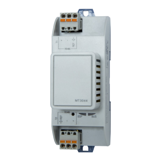
Modbus Network. It has three pins: + , -, and Ref. The module has two RS-485 ports, but only the top connector (Channel 0) is used (Figure IM 969-5 • MICROTECH III CHILLER UNIT CONTROLLER www.DaikinApplied.com... -
Page 7: Installation
“Off” from inside the control panel of the unit. This must be done prior to installing a new communication module. Figure 6 for switch location. Knockout Slot in module must line up permanently with baffle in the board-to- removed board connector www.DaikinApplied.com IM 969-5 • MICROTECH III CHILLER UNIT CONTROLLER... -
Page 8: Replacing A Communication Module
5. Grasp the Modbus communication module and carefully pull it from the unit controller (or from an adjacent module, if it is attached to one). 6. Install the new Modbus communication module: IM 969-5 • MICROTECH III CHILLER UNIT CONTROLLER www.DaikinApplied.com... -
Page 9: Network Configuration
(Figure 10). If you have already to complete the configuration process. entered a password, skip to Step 4. 3. Select Enter Password by pressing down on the circular knob. www.DaikinApplied.com IM 969-5 • MICROTECH III CHILLER UNIT CONTROLLER... -
Page 10: Set The Baud Rate
This equipment must be properly grounded. Only personnel knowledgeable in the operation of the equipment being controlled must perform connections NOTE: Refer to the applicable MicroTech III Chiller Unit and service to the unit controller. Controller Operation Manual for additional information on using keypad/display to set unit parameters and 1. -
Page 11: Configurable Parameters
NOTE: If the unit controller application software requires a field upgrade, the network configuration parameters revert to their default values. Please contact the Chiller Technical Response Center at 540-248-9239 (techresponse@daikinapplied.com) for assistance. www.DaikinApplied.com IM 969-5 • MICROTECH III CHILLER UNIT CONTROLLER... -
Page 12: Parts And Service
Network connector (3-pin) 193410303 communication module, and the network based on the Board-to-board connector (10-pin) 300047027 LED activity. To find your local parts office, visit www.DaikinApplied.com call 800-37PARTS (800-377-2787 IM 969-5 • MICROTECH III CHILLER UNIT CONTROLLER www.DaikinApplied.com... - Page 14 Daikin Applied Training and Development Now that you have made an investment in modern, efficient Daikin equipment, its care should be a high priority. For training information on all Daikin HVAC products, please visit us at www.DaikinApplied.com and click on Training, or call 540-248-9646 and ask for the Training Department.
Need help?
Do you have a question about the MicroTech III and is the answer not in the manual?
Questions and answers