
Related Manuals for Daikin MicroTech III DPS


Summary of Contents for Daikin MicroTech III DPS
- Page 1 Installation and Maintenance Manual OM 1263 Group: Applied Air Systems Part Number: OM 1263 Date: June 2018 MicroTech III Unit Controller for ® Rebel Refrigeration Only Controls ® Model DPS...
-
Page 2: Table Of Contents
Table of Contents Table of Contents Introduction . . . . . . . . . . . . . . . . . . . . . . . . . . . . . . . . . . . . . . . . . . . . . 4 Trending . - Page 3 Table of Contents Heat Pump Control . . . . . . . . . . . . . . . . . . . . . . . . . . . . . . . . . . . . 59 Appendix –...
-
Page 4: Introduction
Operation of this equipment in a residential area is likely to cause harmful interference in which case the user is required to correct the interference at his own expense. Daikin Applied disclaims any liability resulting from any interference or for the correction thereof . -
Page 5: Introduction
Introduction Introduction Getting Started CAUTION Extreme temperature hazard . Can cause damage to This manual contains information designed to assist the field system components . technician with unit setup . The technician will need to be familiar with the following topics at a minimum to successfully The MicroTech III controller is designed to operate in ambient temperatures set up unit operation . -
Page 6: Ifb Board
The IFB board is used to translate between the MicroTech III interconnected forming the ACS1 communication loop . On controller Modbus and the Daikin inverter compressor/outdoor 208/230V units the A4P board controls both INV and OF1 . On fan boards’ proprietary protocol . -
Page 7: Using The Keypad/Display
Using the Keypad/Display Using the Keypad/Display The keypad/display consists of a 5-line by 22 character display, The keypad/display Information is organized into Menu groups; three keys and a “push and roll” navigation wheel . There is an Main Menu, Quick Menu, View/Set Unit Menu, Commission Alarm Button, Menu (Home) Button, and a Back Button . -
Page 8: Passwords
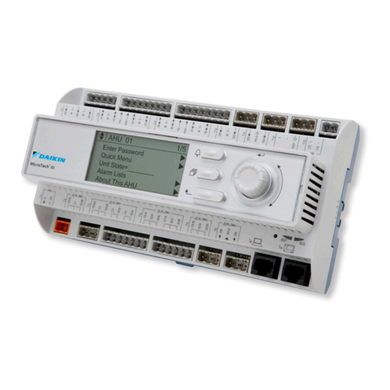
Using the Keypad/Display Passwords Various menu functions are accessible or inaccessible, Figure 5: Password Main Page depending on the access level of the user, and the password AHU 01 they enter, if any . There are four access levels, including no Enter Password password, Level 2, Level 4, and Level 6, with Level 2 having Quick Menu... -
Page 9: Navigation Mode
Using the Keypad/Display Navigation Mode Edit Mode In the Navigation Mode, when a line on a page contains no The Editing Mode is entered by pressing the navigation wheel editable fields all but the value field of that line is highlighted while the cursor is pointing to a line containing an editable field. -
Page 10: Keypad/Display Menu Structure
Keypad/Display Menu Structure Keypad/Display Menu Structure The following is a description of the MicroTech III menu structure . These menus and items can all be displayed with the keypad/ display. Menu items displayed will change based on the selected unit configuration. Figure 7: Main Menu –... - Page 11 Keypad/Display Menu Structure See page 31 — 31 See page 32 — 35 See page 32 See page 36 See page 16 Manual Control Service Menus Unit Maintenance Unit Configuration Alarm Lists ► ► Manual Control= Normal Timer Settings Operating Hours Apply Changes= No Active Alarms ►...
- Page 12 Keypad/Display Menu Structure Figure 8: View/Set Unit – Keypad/Display Menu Structure See page 18 — 21 View/Set Unit ► Unit Status/Settings ► Temperatures ► Flow Status ► SAF Spd Control ► RF/EF Control ► Date/Time/Schedules See page 21 See page 18 — 19 See page 20 See page 20 See page 20...
- Page 13 Keypad/Display Menu Structure Figure 9: Commission Unit – Keypad/Display Menu Structure See page 22 — 30 Commission Unit ► Unit Set-Up ► Timer Settings ► SAF Set-Up ► RF/EF Set-Up ► INV Cmp Set-Up ► OA Fan Set-Up ► Exp Valve Set-Up ►...
- Page 14 Keypad/Display Menu Structure Figure 10: Service Menu – Keypad/Display Menu Structure See page 32 — 35 Service Menus ► Timer Settings ► Operating Hours ► Save/Restore Settings ► Active Alarms ► Alarm Log ► Event Log ► Alarm/Event Config ► Analog Input Status ►...
- Page 15 Keypad/Display Menu Structure See page 33 See page 33 See page 33 Alarm Log Event Log Alarm/Event Config ► ► Log Count: xx Clr Log= No Log Count: xx Clr Log= No ALARM DELAYS ► ► +/-Alarm 1: Alarm Type +/-Alarm 1: Alarm Type Sens Alm Dly= 30s ►...
- Page 16 Keypad/Display Menu Structure Figure 11: Trending – Keypad/Display Menu Structure See page 38 Trending Trending Ena= No Apply Chgs= No Sample Time= 300s TrendOnOff= Off Export Data= No Clear Trend= Done TrendFull= Wrap DefaultTrend= No ► Points 1–8 ► Points 9–24 ►...
-
Page 17: Quick Menu
Quick Menu Quick Menu Items in the Quick Menu (see Table 2) contain basic unit operating status and control set point parameters . The items shown in the Quick Menu are Read Only if a valid password has not been entered . The following are brief descriptions of the Quick Menu items . No password is required to view the Quick Menu. -
Page 18: View/Set Menu
View/Set Menu View/Set Menu Unit Status Settings The “Unit Status Settings” menu provides a summary of basic unit status and control items. This menu summarizes the current operating state of the unit, giving the operating state the unit is in, along with the current capacity level of that operating state . Table 3: Unit Status Settings Item Display Name Default Setting... - Page 19 View/Set Menu System Mode is an adjustable item that sets the status for Clg Status is a status only item which indicates whether or not the for the unit to run on local with field inputs are ignored or mechanical cooling is currently allowed . If cooling is disabled, remote where operation is based on field inputs the reason is indicated .
-
Page 20: Temperature Menu
View/Set Menu Temperature Menu Menus in the Temperatures menu contain unit temperature status information . Table 4: Temperature Menu Item Display Name Default Setting Range Password Level OA Temp= — -50 .0 – 200 .0°F DRT1= — -50 .0 – 392 .0°F DRT3= —... -
Page 21: Time/Date Menu
View/Set Menu Time/Date Menu Table 8: Time/Date Item Display Name Default Setting Range Password Level Time= — 0 – 23: 0 – 59: 0 – 59 Date= — 1 – 12/0 – 31/1970 – 9999 UTC Diff= — DLS Strt Mon= 1stSun 2ndSun DLS Strt Wk=... -
Page 22: Commission Unit
Commission Unit Commission Unit Unit Setup SAF Set-up (See page 22 for more information) Table 9: Unit Setup Menu Default Password Table 11: Supply Fan Speed Menu Item Display Name Range Setting Level Eng Units= English English, SI Item Display Default Setting Range Password Level... -
Page 23: Rf/Ef Set-Up
Commission Unit RF/EF Set-Up (See page 23 for more information) Table 12: Return Fan/Exhaust Fan Set-up Menu Item Display Default Setting Range Password Level Name MaxVentSpd= 100% 0 – 100% Max RFEF RPM= 2600 0 – 5000 Max RF/EF Hz= 60.0Hz 0 –... -
Page 24: Inverter Compressor Set-Up
Commission Unit Inverter Compressor Set-Up (See page 51 — 56 for more information) Table 13: Inverter Compressor Set Up Menu Item Display Item Display Default Setting Range Password Level Default Setting Range Password Level Name Name Compressor Setup Compressor Status Clg Stg Time= 5min 3 –... - Page 25 Commission Unit Clg State is a status only item which displays the current Mechanical cooling operation is disabled when the outdoor air compressor operating state when the unit is in the Cooling temperature sensor input falls below this set point . operating state or when dehumidification operation is active.
-
Page 26: Outdoor Air Fan Set-Up
Commission Unit Outdoor Air Fan Set-Up Table 14: Outdoor Air Fan Set Up Menu OA Fan1 Spd is a status only item that displays the current speed of outdoor fan 1 in percent of maximum speed . Item Display Default Setting Range Password Level OA Fan1 Cmd= is is a status only item that indicates the... -
Page 27: Expansion Valve Set-Up
Commission Unit Expansion Valve Set-Up EVO Pos (Heat Pump only) is a status only item which Table 15: Expansion Valve Set Up Menu displays the current position of the outdoor expansion valve . Item Display Default Password Range Name Setting Level EVI Pos is a status only item which displays the current position of the indoor expansion valve . - Page 28 Commission Unit IRT (Heat Pump only) is a status only item which displays the OC SC Spt is an adjustable item that sets a base value for the current indoor refrigerant temperature sensor reading . Eff SC Spt during cooling operation. ORT (Heat Pump only) is a status only item which displays the OC SC DB is an adjustable item that sets a deadband around current outdoor refrigerant temperature sensor reading .
-
Page 29: Defrost Set-Up
Commission Unit Defrost Set-Up (See page 67 for more information) Defrost State (Heat Pump only) is a status only item which displays the current state of defrost operation . The states are Off, Initialization, Execute and Terminate. Table 16: Defrost Set Up Menu Manual DF (Heat Pump only) is an adjustable item that allows Item Display Default... -
Page 30: Alarm Menus
Alarm Menus Alarm Menus Alarm/Event Configuration Menu Alarm Delays Menu The Alarm Delays Setup Menu can be accessed when a level 2 password has been entered . The default settings are the result of many years of testing and should not be changed . Table 17: Alarm Delays Setup Menu Sens Alm Dly is an adjustable item used to set the sensor Item Display... -
Page 31: Manual Control Menu
Manual Control Menu Manual Control Menu Manual Control The manual control of operation is a function that is used for INV Spd Cmd is an adjustable item that sets the speed of the operating the unit during a service call only . The unit must not inverter compressor . -
Page 32: Service Menus
Service Menus Service Menus Save/Restore Menu Operating Hours The Save/Restore menu can be used to save or restore the The Operating Hours menu gives a summary of the hours of user configured parameters as well as reset the controller back operation for each of the supply fans, return/exhaust fans, to the factory default parameters . -
Page 33: Active Alarms Menu
Service Menus Active Alarms Menu Alarm Configuration Menu All active alarms as well as the date and time that they were The Alarm Configuration menu is also available under the detected are displayed on the Active Alarm menu . These Commission Unit menu . -
Page 34: Universal I/O Status Menu
Service Menus Universal I/O Status Menu Digital Input Status Menu The Universal I/O Status Menu provides diagnostic information The Digital Input Status Menu provides diagnostic information to qualified service personnel. The items listed in this menu to qualified service personnel. The items listed in this menu will provide current status information of the Universal inputs will provide current status information of the controller’s digital &... -
Page 35: Modbus Status Menu
Service Menus Modbus Status Menu Sensor Offsets Menu The Modbus Status Menu provides diagnostic information The Sensor Offsets Menu provides a means of calibrating the to qualified service personnel. The items listed provide the various temperature sensor inputs to the unit . Each sensor status of the Modbus communications with the various devices can be “biased”... -
Page 36: Unit Configuration Setup
Unit Configuration Setup Unit Configuration Setup Unit Configuration Setup Menu After the main control board application software is loaded Table 29 lists the configuration code variables including the into the MCB, it must be “configured” for the specific position within the code, description of the parameter, and the control application . - Page 37 Unit Configuration Setup “ROC Configuration Code Position Description Values (Default in Bold) Applicability” 0=None ● Return Fan Type 6=EBMVAV 7=EBMCAV 0=None ● 1=Tracking Return/Exhaust Fan Capacity Control 2=Building Pressure Method 3=Speed/Network 4=OADamper 0=No Second Duct Pressure Sensor 1=Yes 0=No Entering Fan Temp Sensor 1=Yes 0=None ●...
-
Page 38: Trending
Trending Trending Trending Menus The Trending Menus allow for setting up and managing onboard Default trending of up to 30 data points within the controller . This data There are thirty default trend points for ROC . They will only not can then be exported to an SD card . -
Page 39: Alarms
Alarms Alarms About this Unit Alarms Alarms provide the user with information about abnormal Table 32: About this Unit Menu conditions that affect unit operation. The cause of the alarm should be investigated and eliminated before the unit or any Menu Display Name Item Display Name disabled equipment in it is placed back into service. -
Page 40: Alarm Clearing
Alarms Alarm Clearing Active alarms can be cleared through the keypad/display . Outdoor Refrigerant Temperature Sensor Alarms are automatically cleared when power is cycled . Alarms Problem (Heat Pump only) – (ORT Sensor: are cleared only if the conditions required to initiate the alarm Problem) do not exist . - Page 41 Alarms Defrost Temperature Sensor Problem (Heat Outdoor Fan Problem – (OA Fan: Problem) Pump only) – (DFT Sensor: Problem) On a single outdoor fan unit this alarm occurs when compressor operation is forced to the Standby state due to an outdoor fan This alarm occurs when the DFT sensor input is shorted or open internal fault for a third time in a 30 minute period .
- Page 42 Alarms Discharge Line Refrigerant Pressure Sensor High Refrigerant Pressure Problem – Problem – (PTD Sensor: Problem) (Hi Press 1: Problem) This alarm occurs when the suction line pressure inputs (PTD) This alarm occurs when either the Cooling High Pressure remains above 611 .6 psi or below 1 .42 psi continuously for 10 Unloading or the Heating High Pressure unloading function has seconds .
- Page 43 Alarms 4 Way Valve Problem - (4WayValve: Problem) This alarm occures only on heat pump units when any of the following conditions are true . When compressor heating state is normal yet the DFT-Teg > 10°F for 15 minutes . When compressor cooling state is normal yet the DFT-Teg <...
-
Page 44: Compressor Protection
Compressor Protection Compressor Protection Compressor Protection Unloading Control Cooling Low Pressure Unloading Control There are a number unloading control functions that limit Normal compressor operation is limited during cooling the staging and speed control of the compressors to protect operation when low suction pressure conditions occur . When them from damage under abnormal operating conditions . - Page 45 Compressor Protection Heating High Pressure Protection Control Fixed Speed Compressor High Discharge Line Temperature Unloading Control Normal compressor operation is limited during heating operation when high discharge pressure or high inverter compressor Normal fixed speed compressor operation is limited when high discharge line temperature conditions occur while the inverter discharge line temperature (DRT3) conditions occur .
- Page 46 Compressor Protection Inverter Compressor High Board Temperature Low Differential Pressure Protection Control Unloading Control Normal compressor operation is overridden when the differential pressure between the high and low side of the Normal compressor operation is limited when inverter refrigeration circuit (PTD-PTS) is abnormally low . This compressor control board indicates an abnormally high board condition can inhibit proper oil return for lubricating the (fin) temperature value.
-
Page 47: Operator's Guide
Operator’s Guide Operator’s Guide The following “Operator’s Guide” sections provide information Determining Unit State regarding the day-to-day operation of the MicroTech III Unit Controller . Topics covered are such common tasks as (See page 58 for more information) scheduling, displaying and clearing alarms, and setting the controller for manual operation . -
Page 48: Start Up Operating State
Operator’s Guide Start Up Operating State Off to Prestart Pressure Equalization When a unit is commanded to start it will always enter the The Compressor Cooling State transitions from OFF to Prestart Startup operating state from the Off operating state. The unit Pressure Equalization when the unit enters the Cooling remains in the Startup operating state for an adjustable time operating state becomes active . -
Page 49: Initialization To Standby For Restart
Operator’s Guide Initialization to Standby for Restart Input Devices The Compressor Cooling State transitions from Initialization PTS (suction refrigerant pressure) – MicroTech III AI to Standby for Restart if one of the Compressor Protection PTD (discharge refrigerant pressure) – MicroTech III AI functions force a transition to Standby for Restart, the inverter DRT1 (INV compressor discharge refrigerant line temperature) compressor or outdoor fan board requests a transition to... -
Page 50: Compressor Control Pi_Loop
Operator’s Guide Compressor Control PI_Loop Fixed Speed Compressor Step Transitions When normal inverter compressor operation is active, the inverter compressor is controlled via a PI_Loop to maintain the Under normal compressor control, when the unit is equipped remote of the manual point . with a fixed speed compressor, special transition steps are taken when starting and stopping the fixed speed compressor. -
Page 51: Inverter Compressor Cooling State Descriptions
Operator’s Guide Inverter Compressor Cooling State Descriptions Pre Start Pressure Equalization The Inverter Compressor Cooling State determines the operation of the following devices: In the Pre Start Pressure Equalization state the SVB valve • Inverter Compressor is opened to divert hot gas leaving the compressor directly •... - Page 52 Operator’s Guide Table 35: Standard Initialization Sequence, 16–28 Tons Device Step 1 Step 2 Step 3 Step 4 Inverter Compressor Speed Inverter Compressor Speed Inverter Compressor Speed = Inverter Compressor Speed = = Increasing 1 step every 20 = Increasing 2 steps every 5 Inverter Compressor &...
- Page 53 Operator’s Guide Table 36: Alternate Initialization Sequence, 3–15 Tons Device Step 1 Step 2 Step 3 Step 4 Inverter Compressor Speed = Inverter Compressor Speed = Inverter Compressor & Comp3 Smaller of Step 12 or Maximum ← Minimum Comp3 = Off Comp3 = Off If OAT ≥50°F or RAT ≥73°F, Inverter Compressor Speed =...
- Page 54 Operator’s Guide Table 37: Alternate Initialization Sequence, 16–28 Tons Device Step 1 Step 2 Step 3 Step 4 Inverter Compressor Speed Inverter Compressor Speed = Inverter Compressor Speed = = Increasing 1 step every 5 Inverter Compressor & Comp3 Minimum Step 2 seconds if PTD-PTD <...
-
Page 55: Normal Cooling
Operator’s Guide Normal Cooling In the Normal Cooling state the following are accomplished: • Indoor coil expansion value is modulated to maintain the suction superheat at the suction superheat set point • Outdoor coil expansion valve is controlled to maintain outdoor coil subcooling at the outdoor coil subcooling set point (heat pump) •... -
Page 56: Pumpdown
Operator’s Guide Pumpdown When compressor operation is no longer needed, the compressor enters the Pumpdown state before entering the Standby for Restart state from either the Initialization or Normal Cooling state. The following describes the operation of the cooling control devices in the Pumpdown state: Table 39: Pumpdown State Step 1 Step 2... -
Page 57: Determining Cooling Status
Operator’s Guide Determining Cooling Status Determining Heat Status Clg Status is a status item which indicates whether or not Htg Status is a status item which indicates whether or not the mechanical cooling is currently allowed . If cooling is disabled, primary source of heating in the unit is currently allowed . -
Page 58: Determining Cooling Capacity
Operator’s Guide Determining Cooling Capacity Auto When the Net App Mode is set to “Auto” heating and cooling Clg Capacity is a status item which indicates the percentage of operation are allowed to operate as required to maintain the the unit maximum cooling capacity currently operating . heating and cooling set points . -
Page 59: Heat Pump Control
Operator’s Guide Heat Pump Control Supplemental Heating/Compressor Heating Transitions A heat pump unit transitions between the Cooling and Heating operating states as described above . If compressor heating is Special action is required when the unit transitions from using available it is used first to provide the heating source during compressor (heat pump) heating to supplemental heating and the Heating states . -
Page 60: Compressor Heating Operation State Machine
Operator’s Guide Heat Pump Operating State Compressor Heating Operation State Prestart Pressure Equalization to Initialization Machine – Heat Pump Units Only The Compressor Heating State transitions from Prestart Pressure Equalization to initialization after ninety seconds. This section applies to heat pump units only . When a unit is configured for heat pump operation the primary source of Initialization to Normal heating is provided by operating the compressors in a heating... -
Page 61: Heat Pump
Heat Pump Heat Pump Inverter Compressor Heating State Descriptions Pre Start Pressure Equalization The Inverter Compressor Heating State determines the operation of the following devices: In the Pre Start Pressure Equalization state the SVB valve is opened to divert hot gas leaving the compressor directly to •... - Page 62 Heat Pump Table 42: Standard Initialization Sequence, 16–28 Tons Device Step 1 Step 2 Step 3 Step 4 Inverter Compressor Speed Inverter Compressor Speed = Inverter Compressor Speed = = Increasing 1 step every 5 Inverter Compressor & Comp3 Minimum Step 2 seconds if PTD-PTD <...
- Page 63 Heat Pump Table 43: Alternate Initialization Sequence, 3–15 Tons Device Step 1 Step 2 Step 3 Step 4 Inverter Compressor Speed = Inverter Compressor Speed = Inverter Compressor & Comp3 Smaller of Step 12 or Maximum ← Minimum Comp3 = Off Comp3 = Off If OAT ≥50°F or RAT ≥73°F, Inverter Compressor Speed =...
- Page 64 Heat Pump Table 44: Alternate Initialization Sequence, 16–28 Tons Device Step 1 Step 2 Step 3 Step 4 Inverter Compressor Speed Inverter Compressor Speed = Inverter Compressor Speed = = Increasing 1 step every 5 Inverter Compressor & Comp3 Minimum Comp3 = Off Step 2 Comp3 = Off seconds if PTD-PTD <...
-
Page 65: Normal Heat Pump Control
Heat Pump Normal Heat Pump Control Normal Heating In the Normal Heating state the following are accomplished: • Compressor capacity (INV and Comp 3) is regulated to maintain the DAT at either the Discharge Air Temperature Heating Setpoint (Unit State=Heating) or the Minimum Discharge Air Temperature Spt (Unit State=MinDAT) •... -
Page 66: Pumpdown
Heat Pump Pumpdown Compressor heating operation enters the Pumpdown state before entering the Standby for Restart state from either the Initialization or Normal Heating state. The following describes the operation of the compressor heating control devices in the Pumpdown state: Table 46: Pumpdown State Step 1 Inverter Compressor Speed = Smaller of Step 12 or maximum... -
Page 67: Defrost Control
Heat Pump Defrost Control (See page 29 for more information) When a compressor is operating under these potential frosting conditions for at least the MinCmpOpTm= period (Default=10 Defrost Operation – Heat Pump Units minutes) and the accumulated compressor operation time since the last defrost cycle exceeds the MinAccCmpTm= Only value (Default=40 minutes), the controller can initiate a defrost... -
Page 68: Way Reversing Valve Control (4Wv)
Heat Pump 4 Way Reversing Valve Control (4WV) – Bypass Solenoid Valve Control (SVB) Heat Pump Units Only DPS units include a bypass solenoid valve that opens when necessary to bypass refrigerant from the high to the low 4WV is energized (On) when the unit is in the MinDAT or side of the inverter compressor to reduce the load on the Heating operating state. -
Page 69: Troubleshooting
Troubleshooting Troubleshooting Inverter Board Fault Codes MicroTech III communicates with the fan and compressor Detailed description and diagnostic instructions are shown on inverter boards via Modbus . If the inverter boards detect the following pages . an unsafe condition they issue the appropriate control commands and an error code can be read at the MicroTech III Figure 17: Inverter Board Fault Codes display as follows:... -
Page 70: Ifbcommstatus
Troubleshooting Troubleshooting Module-to-Module Communication INVErr: Communication between the A4P board controlling There are three status parameters on the HMI that are designed to aid in diagnosing communication problems inverter compressor (INV) and the ACS1 communication loop related to the IFB board . These are IFBCommStatus=, ACS1 has been interrupted for 20 seconds after communication had DataRcvd= and ACS3 DataRcvd= and are described below . -
Page 71: Acs1 Datarcvd
Troubleshooting ACS1 DataRcvd ACS3 DataRcvd Upon power up the IFB board receives initial confirmation Upon power up the IFB board receives confirmation data data from all the devices that are connected to the ACS1 from all the devices that are connected to the ACS3 channel . channel. - Page 72 Troubleshooting Figure 18: Unit will not Start with Compressor Cooling ...
- Page 73 Troubleshooting Figure 19: Unit will not Heat with Compressor Heating ...
-
Page 74: Check 1
Troubleshooting The Check 1, Check 2 and Check 3 procedures on page 74 and 75 are used to troubleshoot many error codes . CHECK 1 Check on connector of fan motor (Power supply cable) 1 . Turn OFF the power supply . Measure the resistance between phases of U,V,W at the motor side connectors (three-core wire) to check that the values are balanced and there is no short circuiting,... -
Page 75: Check 3 - Power Resistor Check
Troubleshooting CHECK 3 – Power Resistor Check www .DaikinApplied .com OM 1263 • MICROTECH UNIT CONTROLLER... -
Page 76: Error Code: E5 - Inverter Compressor Motor Lock
Troubleshooting ERROR CODE: E5 – Inverter Compressor Motor Lock Remote Controller Display Inverter PC board takes the position signal from UVW line connected between the inverter Method of and compressor, and the malfunction is detected when any abnormality is observed in the Malfunction Detection phase-current waveform . - Page 77 Troubleshooting Figure 20: E5 – Inverter Compressor Motor Lock Check 3 See page 75 www .DaikinApplied .com OM 1263 • MICROTECH UNIT CONTROLLER...
-
Page 78: Error Code: E7 - Malfunction Of Outdoor Unit Fan Motor
Troubleshooting ERROR CODE: E7 – Malfunction of Outdoor Unit Fan Motor Remote Controller Display Detect a malfunction based on the current value in the INVERTER PC board (as for motor 2 current value in the fan PC board) . Method of Malfunction Detect a malfunction for the fan motor circuit based on the number of rotation detected by Detection... - Page 79 Troubleshooting Figure 21: E7 – Malfunction of Outdoor Unit Fan Motor (Referring to the information on page (Referring to the information on page www .DaikinApplied .com OM 1263 • MICROTECH UNIT CONTROLLER...
-
Page 80: Error Code: H7 - Abnormal Outdoor Fan Motor Signal
Troubleshooting ERROR CODE: H7 – Abnormal Outdoor Fan Motor Signal Remote Controller Display Method of Detection of abnormal signal from fan motor . Malfunction Detection Malfunction In case of detection of abnormal signal at starting fan motor . Decision Condition ●... -
Page 81: Error Code: L1 - Defective Inverter Pc Board
Troubleshooting ERROR CODE: L1 – Defective Inverter PC Board Remote Controller Display Malfunction is detected based on the current value during waveform output before starting compressor . Method of Malfunction Malfunction is detected based on the value from current sensor during synchronous Detection operation when starting the unit . - Page 82 Troubleshooting Figure 22: L1 – Defective Inverter PC Board Check 3 Check 3 Check 3 for Check 3 information See page 75 OM 1263 • MICROTECH UNIT CONTROLLER www .DaikinApplied .com...
-
Page 83: Fin Temperature Rise
Troubleshooting ERROR CODE: L4 – Malfunction of Inverter Radiating Fin Temperature Rise Remote Controller Display Method of Fin temperature is detected by the thermistor of the radiation fin. Malfunction Detection Malfunction When the temperature of the inverter radiation fin increases above 188.6°F. Decision Condition ●... - Page 84 Troubleshooting Figure 23: L4 – Malfunction of Inverter Radiating Fin Temperature Rise OM 1263 • MICROTECH UNIT CONTROLLER www .DaikinApplied .com...
-
Page 85: Thermistor Resistance/Temperature Characteristics
Troubleshooting Figure 24: L4 – Malfunction of Inverter Radiating Fin Temperature Rise Thermistor Resistance/Temperature Characteristics www .DaikinApplied .com OM 1263 • MICROTECH UNIT CONTROLLER... -
Page 86: Inverter Compressor
Troubleshooting ERROR CODE: L5 – Momentary Overcurrent of Inverter Compressor Remote Controller Display Method of Malfunction is detected from current flowing in the power transistor. Malfunction Detection When an excessive current flows in the power transistor. Malfunction Decision (Instantaneous overcurrent also causes activation . ) Condition ●... - Page 87 Troubleshooting Figure 25: L5 – Momentary Overcurrent of Inverter Compressor Check 3 Check 3 See page 75 www .DaikinApplied .com OM 1263 • MICROTECH UNIT CONTROLLER...
-
Page 88: Error Code: L8 - Momentary Overcurrent Of
Troubleshooting ERROR CODE: L8 – Momentary Overcurrent of Inverter Compressor Remote Controller Display Method of Malfunction is detected from current flowing in the power transistor. Malfunction Detection When overload in the compressor is detected . (Inverter secondary current 16 . 1 A) For 460V units (1) 19 .0A and over continues for 5 seconds . - Page 89 Troubleshooting Figure 26: L8 – Momentary Overcurrent of Inverter Compressor Check 3 Check 3 See page 75 www .DaikinApplied .com OM 1263 • MICROTECH UNIT CONTROLLER...
-
Page 90: Error Code: L9 - Inverter Compressor Starting Failure
Troubleshooting ERROR CODE: L9 – Inverter Compressor Starting Failure Remote Controller Display Method of Detect the failure based on the signal waveform of the compressor . Malfunction Detection Malfunction Starting the compressor does not complete . Decision Condition ● Defective compressor ●... - Page 91 Troubleshooting Figure 27: L9 – Inverter Compressor Starting Failure Caution: Be sure to turn off power switch before connecting or disconnecting connectors to prevent parts damage . Check if the compressor lead wires are Fix the compressor lead wire disconnected Correct the wiring;...
-
Page 92: Error Code: P1 - Inverter Over-Ripple Protection
Troubleshooting ERROR CODE: P1 – Inverter Over-Ripple Protection Remote Controller Display Imbalance in supply voltage is detected in PC board . Method of Malfunction Imbalance in the power supply voltage causes increased ripple of voltage of the main Detection circuit capacitor in the inverter. Consequently, the increased ripple is detected. “P1”... - Page 93 Troubleshooting Figure 28: P1 – Inverter Over-Ripple Protection www .DaikinApplied .com OM 1263 • MICROTECH UNIT CONTROLLER...
-
Page 94: Fin Temperature Rise Sensor
Troubleshooting ERROR CODE: P4 – Malfunction of Inverter Radiating Fin Temperature Rise Sensor Remote Controller Display Resistance of radiation fin thermistor is detected when the compressor is not operating. Method of Malfunction “P4” will be displayed by pressing the inspection button . Detection ●... - Page 95 Troubleshooting Figure 29: P4 – Malfunction of Inverter Radiating Fin Temperature Rise Sensor Figure 30 on page 96 www .DaikinApplied .com OM 1263 • MICROTECH UNIT CONTROLLER...
-
Page 96: Thermistor Resistance/Temperature Characteristics
Troubleshooting Figure 30: P4 – Malfunction of Inverter Radiating Fin Temperature Rise Sensor Thermistor Resistance/Temperature Characteristics OM 1263 • MICROTECH UNIT CONTROLLER www .DaikinApplied .com... -
Page 97: Error Code: Pj - Faulty Field Setting After Replacing Main Pc Board Or Faulty Combination Of Pc Board
Troubleshooting ERROR CODE: PJ – Faulty Field Setting after Replacing Main PC Board or Faulty Combination of PC Board Remote Controller Display Method of This malfunction is detected according to communications with the inverter . Malfunction Detection Malfunction Make judgment according to communication data on whether or not the type of the Decision inverter PC board is correct . -
Page 98: Error Code: U2 - Power Supply Insufficient Or
Troubleshooting ERROR CODE: U2 – Power Supply Insufficient or Instantaneous Failure Remote Controller Display Method of Detection of voltage of main circuit capacitor built in the inverter and power supply voltage . Malfunction Detection When the voltage aforementioned is not less than 780V or not more than 320V, or when Malfunction the current-limiting voltage does not reach 200V or more or exceeds 740V . -
Page 99: Www .Daikinapplied .Com
Troubleshooting Figure 31: U2 – Power Supply Insufficient or Instantaneous Failure See CHECK3 page 75 See CHECK3 page 75 www .DaikinApplied .com OM 1263 • MICROTECH UNIT CONTROLLER... -
Page 100: Appendix - General
Appendix – General Appendix – General Supply Fan Failure Codes HLL = Hall Sensor Error First occurrence: Power fluctuations may be responsible. Corrective: Reset the failure; re-start the motor and observe it. If applicable, filter out the source of the disturbing voltage. Repeated occurrence: Question: Do other fans show the same failure? -
Page 101: Tfe = Power Mod Overheated
Appendix – General TFE = Power Mod Overheated First occurrence: Excessive ambient temperature may be responsible. Question: • Do other fans (temporarily) show the same failure within the arrangement? Could ambient temperature have been too high? Or is the motor overloaded? •... -
Page 102: Pha = Phase Failure
Appendix – General PHA = Phase failure UzLow = DC-Link Undervoltage UzHigh = DC-Link Overvoltage UeHigh = Mains Overvoltage UeLow = Mains Undervoltage Question: • Can the main voltage be measured at any spot; a data logger may be helpful . No: Measure the voltage at the power supply input of the concerned fan . - Page 103 Appendix – General Trending Selection Lists Table 73: Primary Trending Select List HMI Name Select Abbreviation Type Bldg Press= 2203 F0AFC4BB Clg State= ClgSt 230B F0AF3991 Clg Status= ClgSts 230B F0AFF6A6 Clg Press Lmtg= ClPLmtg 230B F0AF3B4E Cmp Ratio Lmtg= CpRLmtg 230B F0AF7BA2...
- Page 104 Appendix – General Table 74: Secondary Trending Select List HMI Name Select Abbreviation Type Alarm Enumeration 230A F0AFCF76 IAQ PPM= CO 2 2203 F0AF7F77 Cmp Ratio Lmtg= CpRLmtg 230B F0AF7BA2 DAT Htg Spt= DAHtgSp 2300 F0AF6054 Dewpoint= Dewpt 230A F0AF532C Dewpoint Spt= DewptSp 2300...
-
Page 105: Appendix - Sample Wiring Diagrams: Rebel 3-15 Tons
Appendix – Sample Wiring Diagrams: Rebel 3-15 Tons Appendix – Sample Wiring Diagrams: Rebel 3-15 Tons Figure 32: DPS005A, 208V with Gas Heat and Exhaust Fan 208V, 3 Phase, 60Hz 103A CUSTOMER 104A SUPPLIED POWER 105A GF-I Wire for CW GFR1 phase monitor 106A... - Page 106 Appendix – Sample Wiring Diagrams: Rebel 3-15 Tons Figure 32 continued: DPS005A, 208V with Gas Heat and Exhaust Fan (160) (160) 120V_H 120V_N 160A 155A CLASS 2 120V 75VA GF1-I TB1 GF1-I GFR1 207A 207B (105) T2A_24V T2A_N (213) 207C 207B T1-G 207B...
- Page 107 Appendix – Sample Wiring Diagrams: Rebel 3-15 Tons Figure 32 continued: DPS005A, 208V with Gas Heat and Exhaust Fan (160) (160) 120V_H 120V_N R-HP1 HP1-I HP1-I 160A 303A 155A R-CCH1 T2-C1 T2-DO1B 160A 305A 155A R-HP1 T3-C2 T3-DO2B 160A (303) 308A 155A T6-DI5...
- Page 108 Appendix – Sample Wiring Diagrams: Rebel 3-15 Tons Figure 32 continued: DPS005A, 208V with Gas Heat and Exhaust Fan &D#10.TRILOB &D#10.TRILOB &D#10.TRILOB &D#10.TRILOB &D#10.TRILOB NOTE: Only wire to bottom of TB2, top is for customer connection. MCB aligned with wireway mounting hole MMP51 MMP10 MMP1...
-
Page 109: Appendix - Sample Wiring Diagrams: Rebel 16-28 Tons
Appendix – Sample Wiring Diagrams: Rebel 16-28 Tons Appendix – Sample Wiring Diagrams: Rebel 16-28 Tons Figure 33: DPS020A, 208V with Hot Water Heat www .DaikinApplied .com OM 1263 • MICROTECH UNIT CONTROLLER... - Page 110 Appendix – Sample Wiring Diagrams: Rebel 16-28 Tons Figure 33 continued: DPS020A, 208V with Hot Water Heat OM 1263 • MICROTECH UNIT CONTROLLER www .DaikinApplied .com...
- Page 111 Appendix – Sample Wiring Diagrams: Rebel 16-28 Tons Figure 33 continued: DPS020A, 208V with Hot Water Heat www .DaikinApplied .com OM 1263 • MICROTECH UNIT CONTROLLER...
- Page 112 Appendix – Sample Wiring Diagrams: Rebel 16-28 Tons Figure 33 continued: DPS020A, 208V with Hot Water Heat OM 1263 • MICROTECH UNIT CONTROLLER www .DaikinApplied .com...
- Page 114 Daikin Applied Training and Development Now that you have made an investment in modern, efficient Daikin equipment, its care should be a high priority. For training information on all Daikin HVAC products, please visit us at www.DaikinApplied.com and click on Training, or call 540-248-9646 and ask for the Training Department.
Need help?
Do you have a question about the MicroTech III DPS and is the answer not in the manual?
Questions and answers