Daikin MicroTech III Installation And Operation Manual
Unit controller remote user interface
Hide thumbs
Also See for MicroTech III:
- Operation manuals (144 pages) ,
- Operating manual (77 pages) ,
- Sales and engineering data sheet (68 pages)
Table of Contents
Advertisement
Installation and Operation Manual
MicroTech
®
Remote User Interface
Roofpak
Singlezone Heating and Cooling Units Models RPS\RDT\RFS\
®
RCS\RPE\RDE
Roofpak
Applied Rooftop Systems Air Handling Units Model RAH
®
Self-Contained Air Conditioning Systems Models SWT\SWP
Rebel
Commercial Packaged Rooftop Systems Model DPS
®
Maverick
II Commercial Packaged Rooftop Systems Models MPS
®
Pathfinder
Air-Cooled Screw Chiller Models AWS/AWV
®
Trailblazer
Air-Cooled Scroll Compressor Chiller Models AGZ-D/AGZ-E
®
III Unit Controller
IM 1005-3
Group: Controls
Part Number: IM 1005
Date: November 2016
Advertisement
Table of Contents

Related Manuals for Daikin MicroTech III


Summary of Contents for Daikin MicroTech III
- Page 1 Installation and Operation Manual IM 1005-3 Group: Controls Part Number: IM 1005 Date: November 2016 MicroTech III Unit Controller ® Remote User Interface Roofpak Singlezone Heating and Cooling Units Models RPS\RDT\RFS\ ® RCS\RPE\RDE Roofpak Applied Rooftop Systems Air Handling Units Model RAH ®...
-
Page 2: Table Of Contents
Environmental Conditions ....4 Synchronize with MicroTech III Unit Controller . . . 11 Installation . . . . . . . . . . . . . . . . . . . . . . . . . . . . . . . . . . . 5 Firmware Upgrade Procedure . -
Page 3: Introduction
Connections and IM 1005-3 November 2016 Added models AWV Pathfinder ® service to the MicroTech III unit controller must be performed chiller and AGZ-E Trailblazer chiller, ® only by personnel knowledgeable in the operation of the... -
Page 4: Reference Documents
Introduction Reference Documents Power • Supplied by the MicroTech III unit controller for direct Pathfinder Chiller connection Model AWS Installation, www.DaikinApplied. Daikin Applied IOM 1202 Operation, and • Separate 24V DAC power supply, optional for daisy chain Maintenance Manual connections, Max 85 mA... -
Page 5: Installation
Installation Please be aware of the following before mounting and installing The following section describes how to mount the remote the remote user interface. user interface and connect it to one or more MicroTech III unit controllers. Location Considerations CAUTION Placement of the remote user interface is necessary to Electrostatic discharge hazard . - Page 6 Installation Figure 2: Removing the Cover of remote user interface Figure 3: Wall and Surface Wiring Connections IM 1005-3 • MICROTECH III REMOTE USER INTERFACE www.DaikinApplied.com...
-
Page 7: Wiring The Remote User Interface
Installation Wiring the Remote User Interface Daisy-Chain Connection Wiring the remote user interface to the MicroTech III unit controller can be done in two different ways: Establish a physical connection from the remote user 1. Daisy-chain connection to as many as eight units. -
Page 8: Direct Connection
NOTE: Power is supplied by the unit controller. If a separate The remote user interface can be wired directly to a single 24V power supply is desired, please contact either MicroTech III unit controller over a standard RJ45 (Ethernet) the Daikin Applied Air Technical Response Center connection. -
Page 9: Operator's Guide
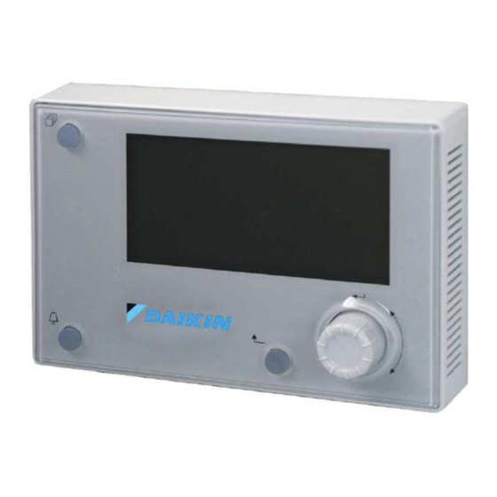
X/Y to indicate line number X of a total of Y lines Figure 7: Remote User Interface Main Features Home Button Navigation Alarm Button Wheel Back Button www.DaikinApplied.com IM 1005-3 • MICROTECH III REMOTE USER INTERFACE... -
Page 10: Alarms
Figure 9: Main Password Page information. See Figure 8 for an example of an active alarm. Also refer to the appropriate MicroTech III unit controller Operation Manual (www.DaikinApplied.com) for available alarm options. Figure 8: Alarm Details Menu The MicroTech III unit controller Operation Manual (www.DaikinApplied.com) provides additional information about... -
Page 11: Synchronize With Microtech Iii Unit Controller
5. Access and adjust the same parameters that are available via the unit controller keypad/display. Refer to the applicable MicroTech III unit controller Operation Manual for the keypad menu structure and detailed description the unit controller sequence of operation (www.DaikinApplied.com). -
Page 12: Firmware Upgrade Procedure
1. Upload the firmware file, POL12289.bin, on the SD-Card in the root directory with no other files. 2. Insert the SD Card into the MicroTech III unit controller. The unit controller must be powered-up and running. 3. Connect the HMI DM to the unit controller. -
Page 13: Troubleshooting
For the first and last units on the daisy-chain trunk, leave the Power Bus supply at the default What if I want to upgrade the MicroTech III unit controller of ON. firmware? b. For all other units within the daisy chain trunk, →... - Page 14 Daikin Applied Training and Development Now that you have made an investment in modern, efficient Daikin equipment, its care should be a high priority. For training information on all Daikin HVAC products, please visit us at www.DaikinApplied.com and click on Training, or call 540-248-9646 and ask for the Training Department.
Need help?
Do you have a question about the MicroTech III and is the answer not in the manual?
Questions and answers