Daikin MicroTech III Operation & Maintenance Manual
Unit controller for water source heat pump units
Hide thumbs
Also See for MicroTech III:
- Operation manuals (144 pages) ,
- Operating manual (77 pages) ,
- Sales and engineering data sheet (68 pages)
Table of Contents
Troubleshooting

Subscribe to Our Youtube Channel
Related Manuals for Daikin MicroTech III


Summary of Contents for Daikin MicroTech III
- Page 1 Operation & Maintenance Manual OM 931-6 Group: WSHP Part Number: 910157590 Date: September 2014 III Unit Controller for Water Source Heat MicroTech ® Pump Units Used with Enfinity Models CCH/CCW, VFC/VFW, MHC/MHW, LVC/LVW...
-
Page 2: Table Of Contents
MicroTech III Unit Controller . . . . . . . . . . . . . . . . . . -
Page 3: Introduction
MicroTech III Unit Controller and Mark IV Unit Controller. ■ IM 928 - MicroTech III Water Source Heat Pump Unit Controller BACnet MS/TP Communication Module. ■ IM 955 - MicroTech III Water Source Heat Pump Wall-Mounted Room Temperature Sensors. -
Page 4: Microtech Iii Unit Controller
H6 – 7 Reversing Valve – Output Neutral Terminal 2 H7 – 1 No Connection Neutral Terminal 3 SWL1 Switch – L1 Voltage H7 – 2 No Connection COMP Relay No Connection OM 931-6 • MicroTech III Unit Controller for WSHP www.DaikinApplied.com... -
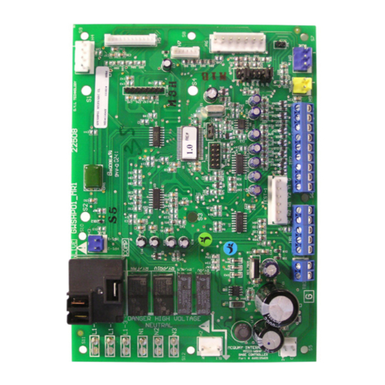
Page 5: Microtech Iii Unit Controller Connections
III u ICro ontroller MicroTech III Unit Controller Connections Figure 1: MicroTech III Unit Controller Terminal Locations OM 931-6 • MicroTech III Unit Controller for WSHP www.DaikinApplied.com... -
Page 6: Replacing A Microtech Iii Circuit Board
Failure to do so can result in unit damage and fluid leaks.” OM 931-6 • MicroTech III Unit Controller for WSHP www.DaikinApplied.com... -
Page 7: General Use And Information
ICro ontroller General Use and Information The MicroTech III unit controller is configured so that when either the Y1 or W1 input is energized the unit fan The MicroTech III unit controller is provided with two is also activated with Cooling or Heating Modes. In other... -
Page 8: Control Outputs {A And Iv/Pr (H8)
When the Y1 terminal is de-energized, the following occurs: 1 . The compressor de-energizes. 2 . The fan de-energizes, unless the G terminal is energized (24VAC), or JP2 is open. OM 931-6 • MicroTech III Unit Controller for WSHP www.DaikinApplied.com... -
Page 9: Unoccupied Operation - Stand Alone Thermostat
Board LED Status – Remote Shutdown Yellow Green Flash When the E terminal is grounded, the MicroTech III unit controller enters remote shutdown mode. Remote shutdown is provided so that when properly connected to a building automation system, remote switch, etc., the E terminal can be used to shut down the water source heat pump. -
Page 10: High / Low Pressure Faults (Hp/Lp)
The MicroTech III unit ■ In heat mode the low temperature fault is subject to controller monitors these switches individually. If the Intelligent Reset. -
Page 11: Condensate Overflow
When the unit operation. If the U terminal is still grounded after MicroTech III unit controller is locked out due to one of the 2-hour time limit, the unit will return to unoccupied these faults, and the cause of the fault condition has mode. -
Page 12: Fan Operation During Most Modes, Faults And Shutdowns
Modes, Faults and Priority of Faults and Modes Shutdowns The MicroTech III unit controller is configured with mode The MicroTech III unit controller allows fan operation and fault priorities. Table 4 illustrates that the lower the during most modes, faults and shutdowns to facilitate priority level number, the higher the priority of the fault or maximum space comfort and control. -
Page 13: Troubleshooting
To avoid electrical shock, personal injury or death, be sure to rigorously adhere to field wiring procedures regarding proper lockout and tagout of components. Figure 6: MicroTech III Unit Controller LED Status and Faults Troubleshooting Reference Read Outputs... -
Page 14: Troubleshooting The Water Source Heat Pump Unit
Check for lock rotor amp Check for low refrigerant draw charge Check amp draw on blower assembly Check for proper water flow and delta T (°F) OM 931-6 • MicroTech III Unit Controller for WSHP www.DaikinApplied.com... -
Page 15: Microtech ® Iii Unit Controller Interface To External
Expansion Module for their internal operation except hose provided by Daikin. Only thermostats offered by Daikin are proven to operate properly with the MicroTech III unit controller. Daikin makes no guarantees about any other thermostat or control device interfaced by the end user with the MicroTech III unit controller. -
Page 16: Start-Up
Lead Compressor Option Shorted Compressor #2 is Lead (Valid for Dual Compressor Models Only) * I/O Expansion module supplied with Secondary Heating Options (Boilerless or Supplemental Electric Heat Options) and ECM motor. OM 931-6 • MicroTech III Unit Controller for WSHP www.DaikinApplied.com... -
Page 17: Operation
(compressor off) the fan motor runs in low speed. If there is a call for heat- ing or cooling (compressor on) the fan motor runs OM 931-6 • MicroTech III Unit Controller for WSHP www.DaikinApplied.com... -
Page 18: Second Circuit Faults
Pin 2 Suction line temperature sensor circuit 2 common Pin 3 Low pressure switch circuit 2 signal Pin 4 Low pressure switch circuit 2 source LED Annunciator For future use OM 931-6 • MicroTech III Unit Controller for WSHP www.DaikinApplied.com... -
Page 19: Microtech Iii Unit Controller With L
Communication Module. orks ■ IM 933 - LonMaker Integration Plug-in Tool: For use with the MicroTech III Unit Controller. ■ IM 955 - MicroTech III Wall Sensor for use with MicroTech III Unit Controller with L orks Microtech III Unit Controller... -
Page 20: Microtech Iii Controller With Bacnet ® Communication
■ Monitors leaving water temperature BACnet Communication Module ■ Relays status of all vital unit functions ■ IM 955 - MicroTech III Wall Sensor For use with The MicroTech III unit controller with Microtech III Unit Controller communication module includes:... -
Page 21: Appendix C - Typical Wiring Diagrams
Return Air Temperature (RAT) sensors shipped loose and are field installed. The Leaving Water Temperature (LWT) sensor is factory installed. Entering Water Temperature (EWT) sensor is included with ECM and/or Secondary Electric Heat. OM 931-6 • MicroTech III Unit Controller for WSHP www.DaikinApplied.com... -
Page 22: Microtech Iii Unit Controller With Optional Ecm Motor, Desuperheater And I/O Expansion Module - 208/230/265/277/60 Hz/1-Phase
IrIng IagraMs MicroTech III Unit Controller with Optional ECM Motor, Desuperheater and I/O Expansion Module – 208/230/265/277/60 Hz/1-Phase Drawing No. 668991501 Wiring diagrams are typical. For the latest drawing version refer to the wiring diagram located on the inside of the controls access panel of the unit. -
Page 23: Microtech Iii Unit Controller With Optional Ecm Motor, Desuperheater, Electric Heat Coil And I/O Expansion Module - 208/230/460/60 Hz/3-Phase
IrIng IagraMs MicroTech III Unit Controller with Optional ECM Motor, Desuperheater, Electric Heat Coil and I/O Expansion Module – 208/230/460/60 Hz/3-Phase Drawing No. 668991301 Wiring diagrams are typical. For the latest drawing version refer to the wiring diagram located on the inside of the controls access panel of the unit. -
Page 24: Microtech Iii Unit Controller With Optional Ecm Motor, Desuperheater, And I/O Expansion Module 208/230/460/60/3-Phase
IrIng IagraMs MicroTech III Unit Controller with Optional ECM Motor, Desuperheater, and I/O Expansion Module 208/230/460/60/3-Phase Drawing No. 668991401 Wiring diagrams are typical. For the latest drawing version refer to the wiring diagram located on the inside of the controls access panel of the unit. -
Page 25: Microtech Iii Unit Controller With Psc Motor, Desuperheater And I/O Expansion Module For Hot Gas Reheat Control (Unit Sizes 019-070) 208/230/60/1-Phase
IrIng IagraMs MicroTech III Unit Controller with PSC Motor, Desuperheater and I/O Expansion Module for Hot Gas Reheat Control (Unit Sizes 019-070) 208/230/60/1-Phase Drawing No. 669007101A Wiring diagrams are typical. For the latest drawing version refer to the wiring diagram located on the inside of the controls access panel of the unit. -
Page 26: Controller Comparison
Controller Comparison Table Note: The Mark IV, MicroTech 2000, Alerton and MicroTech III boards are NOT interchangeable. Table 12: Control Boards and Features Alerton MicroTech 2000 Mark IV MicroTech III Features DC Power ● – – – AC Power ●... - Page 27 This page left intentionally blank OM 931-6 • MicroTech III Unit Controller for WSHP www.DaikinApplied.com...
- Page 28 Daikin Applied Training and Development Now that you have made an investment in modern, efficient Daikin equipment, its care should be a high priority. For training information on all Daikin HVAC products, please visit us at www.DaikinApplied.com and click on Training, or call 540-248-9646 and ask for the Training Department.
Need help?
Do you have a question about the MicroTech III and is the answer not in the manual?
Questions and answers