Daikin MicroTech III Installation And Maintenance Manual
Smartsource unit controller with i/o expansion module for single and two stage water source heat pumps
Hide thumbs
Also See for MicroTech III:
- Operation manuals (144 pages) ,
- Operating manual (77 pages) ,
- Sales and engineering data sheet (68 pages)
Table of Contents
Advertisement
Quick Links
Installation and Maintenance Manual
MicroTech
®
Expansion Module for Single and Two Stage Water
Source Heat Pumps
For Models GC,GS, GT, VH
I/O Expansion Module
III SmartSource
Unit Controller with I/O
®
MicroTech III SmartSource Unit Controller
OM 1149-5
Group: WSHP
Document PN: 910313452
Date: April 2020
Advertisement
Table of Contents
Troubleshooting

Subscribe to Our Youtube Channel
Related Manuals for Daikin MicroTech III


Summary of Contents for Daikin MicroTech III
- Page 1 Group: WSHP Document PN: 910313452 Date: April 2020 MicroTech III SmartSource Unit Controller with I/O ® ® Expansion Module for Single and Two Stage Water Source Heat Pumps For Models GC,GS, GT, VH I/O Expansion Module MicroTech III SmartSource Unit Controller...
-
Page 2: Table Of Contents
MicroTech III Unit Controller . . . . . . . . . . . . . . . . . . -
Page 3: Introduction
■ IM 927 - MicroTech III Water Source Heat Pump Communication Module orks ■ IM 928 - MicroTech III Water Source Heat Pump Unit Controller BACnet MS/TP Communication Module www .DaikinApplied .com OM 1149-5... -
Page 4: Microtech Iii Unit Controller
III u ICro ontroller Unit Controller and Control Modules Terminals and Connectors Descriptions Table 1: MicroTech III unit controller terminals & descriptions H7 – 2 No Connection H7 – 3 Red LED Output H1 – 1 24 VAC Power Input H7 –... -
Page 5: I/O Expansion Module
III u ICro ontroller I/O Expansion Module BACnet Communication Module Table 2: I/O expansion module connectors/terminals Table 3: BACnet communication module connectors/ terminals H1 – 1 H1 – 2 P4 – 1 H1 – 3 P4 – 2 + 5 VDC H1 –... -
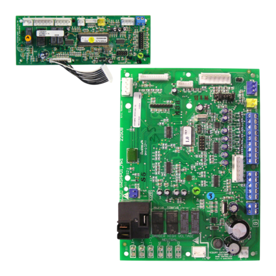
Page 6: Connections
III u ICro ontroller MicroTech III Unit Controller & I/O Expansion Module Connections Figure 1: MicroTech III unit controller & I/O expansion module connectors descriptions Note: Refer to Table 1 on page 4 for MicroTech III controller terminal descriptions and... -
Page 7: Replacing A Microtech Iii Unit Controller
Shorted for 55° to 95°F adjustment range Open for thermostatic room control Room control type Shorted for room temperature sensor control, MicroTech III only . Open to enable compressor heating Compressor heating source Shorted to disable compressor heating... - Page 8 III u ICro ontroller Table 6: I/O expansion module jumper settings I/O Expansion Description Jumper(s) Setting Model JP1 = Open Fan Row “A” Selected JP2 = Open JP1 = Shorted Fan Row Select for Operating Modes: Fan Row “B” Selected JP2 = Open ▪...
-
Page 9: General Use And Information
. No external power sources may be used to operate mode is typically initiated by the BAS with smart grid MicroTech III . All units must be properly grounded per local technologies to save energy . The savings is driven by code requirements . -
Page 10: Control Outputs [A And Iv/Pr (H8)]
“ON” or a wall sensor command .) at activation of the G terminal . “FAN ONLY” setting . The H8 output on the MicroTech III Note: If jumper JP2 on the main control board is open board is activated to open the motorized valve allowing the fan will run continuous whenever there is a water flow thru the heat exchanger. - Page 11 45 second flow timer and the 360 second compressor minimum off timer has expired . The above 90°F the H8 output on the MicroTech III board is activated to open the motorized valve diverting compressor minimum on timer of 180 seconds starts .
- Page 12 III u ICro ontroller Waterside Economizer • On a call from Y2 of the thermostat or BMS cooling stage 2 setpoint, and the EWT is below the hydronic This mode requires the optional factory-installed cooling setpoint, but above 35°F, the unit will operate waterside economizer .
-
Page 13: Unit Status
Board LED Status – Remote Shutdown Yellow Green Flash When the E terminal is grounded, the MicroTech III unit controller enters remote shutdown mode . Remote Fault Modes shutdown is provided so that when properly connected to a building automation system, remote switch, etc ., the... -
Page 14: High / Low Pressure Faults (Hp/Lp)
. The Fan speed is not changed, however “Heat Stage #1” MicroTech III unit controller monitors these switches speed is used if the fan is presently off . individually . If the compressor is running and the HP... -
Page 15: Condensate Overflow
Override/Reset Button for more than 10 seconds • Turn the unit power off and wait 10 seconds to turn The MicroTech III unit controller's condensate sensor is back on . designed to detect excessively high condensate water When the cause of the fault condition has been levels in the drain pan . -
Page 16: Fan Operation During Most Modes, Faults And Shutdowns
Time (Sec) Shutdowns Alarm Condition or Network “Wink” 0 .5 0 .5 Operation Active The MicroTech III unit controller allows fan operation 0 .0 Continually Bypass Mode is Active during most modes, faults and shutdowns to facilitate 0 .5 5 .5 Unoccupied Mode maximum space comfort and control . -
Page 17: Troubleshooting
MicroTech III Unit Controller LED Faults Troubleshooting I/O Expansion Communication Fail Description Type Yellow Green I/O Expansion Fail Fault Flash • Verify connection of 12 wire cable between H5 on the main board and H1 on the I/O expansion board is fully engaged in the connector. - Page 18 MicroTech III Unit Controller LED Faults (Continued) Freeze Fault Detect Description Type Yellow Green Freeze Fault Detect Fault Flash Flash • Low entering water temperature (below 35°F standard range or 13.5°F extended range) Condensate Overflow (Freeze Fault Protection Only)
-
Page 19: Troubleshooting The Water Source Heat Pump Unit
roubleshootIng Troubleshooting the Water Source Heat Pump Unit Figure 7: Troubleshooting guide - unit operation Unit control, check thermostat Low voltage, check Fuse may be blown, Wire may be loose or broken. for correct wiring or faulty power supply voltage circuit breaker is open Replace or tighten wires thermostat... -
Page 20: Start-Up
Operation: The MicroTech III unit controller’s valve or pump request terminal [IV/PR (H8)] is an output signal to external devices Fan Main Output: will turn ON and the Fan PWM signal to allow water flow as required by the heat pump. The IV/ will be at “Auxiliary Heat”... -
Page 21: Compressor Heating Source Selection
III u ICro ontroller Compressor Heating Source Fan Speed Selector Switch Selection A 4-position fan speed selector switch located in the control box allows CFM settings to be field adjustable Compressor heating source selection provides a method to with some fan options . Fan speed control optimizes unit disable the compressor operation when in the heating mode . -
Page 22: Unit Options
■ Items Required: ■ Application: • Multi-stage thermostat or sensor By utilizing a basic thermostat and configuring the Microtech III unit controller for this mode of operation, ■ Unit Control Settings: the WSHP will provide maximum latent capacity by •... -
Page 23: Hot Gas Reheat Smart Dehumidification
III u ICro ontroller ■ Operation: Figure 14: Model GT thermostat and sensor combination hot gas reheat smart dehumidification wiring diagram Unit will run at maximum compressor capacity with low CFM to maximize latent capacity . Model GT Unit Thermostat Example: A 2-stage model GT, unit size 026, wired for 24VAC Simplified Dehumidification:... -
Page 24: Humidistat Controlled Dehumidification
III u ICro ontroller Figure 16: SmartSource MicroTech III controller to digital room temperature sensor wiring MicroTech III Board SmartSource Board Expansion Module Base Board Terminal Block Label TB2-1 TB1-1 TB1-2 TB1-3 TB1-4 TB1-5 TB3-1 TB3-2 TB1-1 Description Terminal Label... -
Page 25: Dehumidification Only
III u ICro ontroller Figure 19: SmartSource MicroTech III controller & I/O expansion module to field supplied room temperature sensor wiring MicroTech III Board SmartSource Board I/O Expansion Module Base Board Terminal Block TB2-1 TB1-1 TB1-2 TB1-3 TB1-4 TB1-5 TB3-1... -
Page 26: Microtech Iii Unit Controller With L On W Orks
Enable heating and cooling to maintain setpoint with the MicroTech III Unit Controller . based on a room sensor • IM 955 - MicroTech III Wall Sensor for use with • Enable fan and compressor operation Microtech III Unit Controller •... -
Page 27: Microtech Iii Controller With An Optional Bacnet® Communication Module
BACnet Communication Module • Relays status of all vital unit functions • IM 955 - MicroTech III Wall Sensor For use with The MicroTech III unit controller with Microtech III Unit Controller an optional communication module Daikin water source heat pumps are available with... -
Page 28: Controller Comparison
Controller Comparison Note: The Mark IV, MicroTech 2000, Alerton and Micro- Tech III boards are NOT interchangeable. Table 14: Control Boards and Features Alerton Mark IV MicroTech 2000 MicroTech III Features DC Power ● – – – AC Power ●... - Page 29 www .DaikinApplied .com OM 1149-5...
- Page 30 OM 1149-5 www .DaikinApplied .com...
-
Page 32: Warranty
Daikin Applied Training and Development Now that you have made an investment in modern, efficient Daikin equipment, its care should be a high priority. For training information on all Daikin HVAC products, please visit us at www.DaikinApplied.com and click on Training, or call 540-248-9646 and ask for the Training Department.
Need help?
Do you have a question about the MicroTech III and is the answer not in the manual?
Questions and answers