Daikin MicroTech III Installation And Maintenance Manual

Daikin MicroTech III Installation And Maintenance Manual

Chiller unit controller/communication module
Hide thumbs Also See for MicroTech III:

Advertisement

Installation and Maintenance Manual
MicroTech
®
L
W
Communication Module
®
on
orks
Models AGZ and AMZ Trailblazer
Models AWS and AWV Pathfinder
Model ADS Air-cooled Global Screw Chiller
Model WME, B Vintage, Magnitude
Model WWV, Navigator
III Chiller Unit Controller
Water-cooled Screw Chiller
®
Air-cooled Scroll Chiller
®
Air-cooled Screw Chiller
®
Magnetic Bearing Centrifugal Chiller
®
IM 968-4
Group: Controls
Part Number: IM 968
Date: January 2018

Advertisement

Table of Contents
loading
Need help?

Need help?

Do you have a question about the MicroTech III and is the answer not in the manual?

Questions and answers

Summary of Contents for Daikin MicroTech III

  • Page 1 Installation and Maintenance Manual IM 968-4 Group: Controls Part Number: IM 968 Date: January 2018 MicroTech III Chiller Unit Controller ® Communication Module ® orks Models AGZ and AMZ Trailblazer Air-cooled Scroll Chiller ® Models AWS and AWV Pathfinder Air-cooled Screw Chiller ®...
  • Page 2: Table Of Contents

    © 2018 Daikin Applied, Minneapolis MN. All rights reserved throughout the world Daikin Applied reserves the right to change any information contained herein without prior notice. The user is responsible for determining whether this product is appropriate for his or her application.
  • Page 3: Introduction

    Interoperability Interoperability Guidelines, is likely to cause harmful interference in which case the user will be required Association Version 3.4 to correct the interference at his or her own expense. Daikin disclaims any LonMark LonMark Functional Profile: www.lonmark. Interoperability 8040_10 liability resulting from any interference or for the correction thereof.
  • Page 4: Features

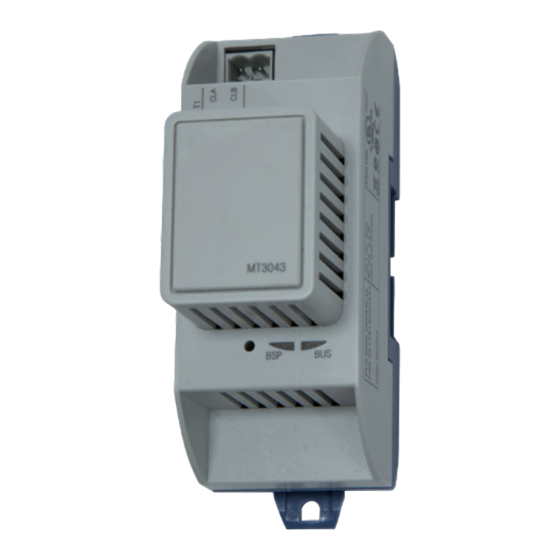
    • Network controller (Neuron chip) handles the complete network protocol and user application orks • Simple attachment to a MicroTech III chiller unit controller • LEDs that indicate communication status and network activity MT3043 • Configurable using standard L...
  • Page 5: Component Data

    It connects directly to the left- orks communication module simply attaches directly to the left side hand side of the MicroTech III chiller unit controller as shown of the existing module instead of the unit controller. Figure 3: L...
  • Page 6: Light Emitting Diodes (Leds)

    (Figure 6 Figure connected to the MicroTech III chiller unit controller and the unit is powered on (Figure Figure 6: Board-to-Board Connector BSP LED The BSP LED indicates the communication state between...
  • Page 7: Bus Termination

    Standard Network Variable Types (SNVTs) and Standard impedance. Network Configuration Parameter Types (SCPTs) used in the MicroTech III chiller unit controller into the variables and parameters used by the L network. The software NOTE: Refer to Echelon L...
  • Page 8: Installation

    Figure 7: Chiller Unit Controller On/Off Switch The following section describes how to field install a new communication module or replace an existing orks module on the MicroTech III chiller unit controller. CAUTION Electrostatic discharge hazard . Can cause equipment damage .
  • Page 9: Replacing A Communication Module

    30 seconds after power has been applied to it. This reset is necessary so that the L communication module can orks synchronize with the unit controller. 9. Set the Unit On/Off Switch to “On” from inside the control panel of the unit. www.DaikinApplied.com IM 968-4 • MICROTECH III CHILLER UNIT CONTROLLER...
  • Page 10: Commissioning And Configuration

    After the L communication module has been installed, The XIF, NXE, and Resource files are available orks the MicroTech III chiller unit controller is ready for integration www.DaikinApplied.com or www.lonmark.org. into a building automation system (BAS). The following Commissioning...
  • Page 11: Enter Password

    Main Menu and then follow steps 1-3. 3. Enter Password 5321 and then press Enter. Figure 10: Unit Controller Main Features Refer to the MicroTech III Chiller Unit Controller Operation Manual (Reference Documents) for additional information on using the keypad/display to set parameters and defaults for unit setpoints.
  • Page 12 This parameter remains blank until the communication module is commissioned. 1. Requires the use of LonMaker or other L configuration tool. See ED 15120 for details (www.DaikinApplied.com). ® orks 2. The LON BSP and software application version are read-only. IM 968-4 • MICROTECH III CHILLER UNIT CONTROLLER www.DaikinApplied.com...
  • Page 13: Parts And Service

    → Confirm that you have the correct transceiver. → Make sure that the network trunk avoids strong sources of electromagnetic interference (EMI). → Verify that the network trunk is not located near a DC load switch (relay). www.DaikinApplied.com IM 968-4 • MICROTECH III CHILLER UNIT CONTROLLER...
  • Page 14 Daikin Applied Training and Development Now that you have made an investment in modern, efficient Daikin equipment, its care should be a high priority. For training information on all Daikin HVAC products, please visit us at www.DaikinApplied.com and click on Training, or call 540-248-9646 and ask for the Training Department.

This manual is also suitable for:

AmzLonworksAwsAwvAdsWme ... Show all

Table of Contents