Daikin Microtech III Operation And Maintenance Manual
Unit controller with i/o expansion module
for two compressor water source heat pumps
Hide thumbs
Also See for Microtech III:
- Operation manuals (144 pages) ,
- Operating manual (77 pages) ,
- Sales and engineering data sheet (68 pages)
Table of Contents
Advertisement
Quick Links
Operation and Maintenance Manual
MicroTech
®
for Two Compressor Water Source Heat Pumps
Large Capacity Vertical Models LVC (Standard Range) & LVW (Extended Range)
Large Capacity Horizontal Models CCH (Standard Range) & CCW (Extended Range)
I/O Expansion Module
III Unit Controller with I/O Expansion Module
MicroTech III Unit Controller
OM 1239
Group: WSHP
Document PN: 910165130
Date: July 2015
Advertisement
Table of Contents

Subscribe to Our Youtube Channel
Related Manuals for Daikin Microtech III


Summary of Contents for Daikin Microtech III
- Page 1 III Unit Controller with I/O Expansion Module for Two Compressor Water Source Heat Pumps Large Capacity Vertical Models LVC (Standard Range) & LVW (Extended Range) Large Capacity Horizontal Models CCH (Standard Range) & CCW (Extended Range) I/O Expansion Module MicroTech III Unit Controller...
-
Page 2: Table Of Contents
MicroTech III Unit Controller . . . . . . . . . . . . . . . . . . -
Page 3: Introduction
■ IM 927 - MicroTech III Water Source Heat Pump Room Sensors orks Communication Module. • ■ IM 928 - MicroTech III Water Source Heat Pump Unit Short or Long Range Setpoint Adjustment for Room Sensor Controls Controller BACnet MS/TP Communication Module. ■ IM 933 - L •... - Page 4 Table 1: Control options Control Description Application Protocol The MicroTech III controller is a Each unit controller is factory Unit-mounted or wall-mounted standalone microprocessor-based programmed, wired, and tested for thermostat or room sensor MicroTech III control board conveniently located...
-
Page 5: Microtech Iii Unit Controller
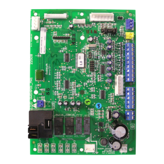
III u ICro ontroller MicroTech III unit controller and I/O expansion module connections Table 2: MicroTech III unit controller terminals locations and descriptions H1 – 1 24 VAC Power Input H8 – 1 Isolation Valve/Pump Request Relay N/O H1 – 2 24 VAC common H8 –... - Page 6 III u ICro ontroller Figure 1: MicroTech III unit controller terminal locations OM 1239 www.DaikinApplied.com...
- Page 7 III u ICro ontroller Table 3: I/O expansion module terminals locations and H3 – 6 Fan Motor – Common descriptions H4 – 1 Entering Water Temp Sensor – Signal H1 – 1 I/O Expansion Board Common (Gnd) H4 – 2 Entering Water Temp Sensor –...
-
Page 8: Bacnet Communication Module
III u ICro ontroller BACnet communication module Figure 3: BACnet communication module connectors and terminals Table 4: BACnet communication module connectors/ BACNET terminals P4 – 1 P4 – 2 + 5 VDC P4 – 3 SPI SELECT (SPI Select To Communications Board) P4 –... -
Page 9: Replacing A Microtech Iii Circuit Board
Initial power-up CAUTION Pre start check list: The MicroTech III circuit board incorporates static sensitive devices. A static charge from touching the device can damage the A random start delay time between 300 and 360 seconds electronic components. To help prevent damage during service, is generated at power up. -
Page 10: I/O Expansion Module Jumper Settings
III u ICro ontroller I/O expansion module jumper settings Table 7: I/O expansion module jumper settings I/O Expansion Description Jumper(s) Jumper Setting Model Not Used Open – Not Used Open – Open None Open Shorted Secondary Heating JP3 & JP4 Supplemental Electric Heat Options Open... -
Page 11: General Use And Information
On a further demand for cooling the second compressor will energize. The waterside The Microtech III unit controller is a water source heat economizer mode will not be activated if the pump control platform used to control the heat pump in entering water temperature is below 35°F and an... -
Page 12: Dehumidification
A simple “grounded” signal between Control will generate a low pressure fault on the terminals U and C on the MicroTech III unit circuit where the switch is open. controller will place the unit into the unoccupied •... - Page 13 If operating in the “Cooling” mode: voltage returns to approximately 90% of the unit • Both compressors will be immediately turn off to nameplate value. The MicroTech III unit controller allow the suction line temperature to recover and measures the input voltage and will suspend...
-
Page 14: Fault Status And Led Annunciation
The fan and pump remain available for operation. able. If both compressors are off on a high or low • pressure fault the MicroTech III will go into Fault Alarm output energizes. mode and neither compressor is available. The previous operation of heating or cooling determines how the low suction temp alarm must be reset. - Page 15 • Mark the occurrence of the fault. freeze solution. Baseboard jumper setting JP3 (loop fluid) defines the operation as “open” if MicroTech III (circuit 2) LED Status – Low Suction Line Temperature Fault water fluid is used or “shorted” if glycol loop fluid Yellow Green is used.
-
Page 16: [A And Iv/Pr (H8)]
Remote shutdown process operation: The control outputs are Alarm Fault (A) and Isolation When the E terminal is grounded, the MicroTech III unit Valve / Pump Request [IV/PR (H8)]. The operation of the controller enters remote shutdown mode. Remote shutdown... -
Page 17: Fault Recovery And Reset
Note: Cycling unit power will always reset any type of fault. Faults will clear as defined in When the MicroTech III unit controller is locked Table out due to one of these faults, and the cause... - Page 18 The W2 terminal controls the second stage of heating. When the W2 terminal is energized, the following occurs: • The MicroTech III unit controller enters tenant The lag compressor is enabled when the interstage override mode when the Tenant Override (TO) timer has expired.
-
Page 19: Fan Operation During Most Modes, Faults And Shutdowns
Table 10: Priority level of faults and modes Alarm Alarm Mode or Fault The MicroTech III unit controller allows fan operation Identifier Priority during most modes, faults and shutdowns to facilitate I/O Expansion Communication Fail maximum space comfort and control. However, the... - Page 20 III u ICro ontroller Table 11: MicroTech III unit controller status LED's Description Type Yellow Green IO Expansion Communication Fail Fault Flash Flash Invalid Jumper Configuration Fault Flash Flash Low Voltage Brownout Fault Flash Emergency Shutdown Mode Flash Compressor #1 High Pressure...
-
Page 21: Microtech Iii Unit Controller Interface To External
MicroTech III unit controller. Daikin makes no guarantees about any other thermostat or control device interfaced Introduction by the end user with the MicroTech III unit controller. • The I/O Communication Module is an expansion of the Care must be used to isolate all external power sources... -
Page 22: I/O Expansion Module Faults And Fan Operating
III u ICro ontroller I/O expansion module faults and fan operating modes Table 13: I/O expansion module LED & fault outputs Description Type Yellow Green Baseboard Communication Fail Fault Flash Flash Compressor #2 High Pressure (HP2) Fault Flash Compressor #2 Low Pressure (LP2) Fault Compressor #2 Low Suction Temp (LT2) Sensor Fail Fault... -
Page 23: Unit Options
III u ICro ontroller Unit options Figure 10: Unit and humidistat-dehumidification only wiring diagram There are two dehumidification modes of operation: Unit Base Board TB2 Thermostat Hot Gas Reheat Dehumidification with Temperature RC 24VAC Control. RH 24VAC Hot Gas Reheat Dehumidification. 24VAC Common Hot gas reheat with temperature Cool Stage #1... - Page 24 6 (FC) Description Sensor Digitally Adjustable Room Temperature Sensor (Part No . 910121754) Figure 13: MicroTech III board & I/O expansion module to field supplied room temperature sensor wiring Control Board MicroTech III Unit Control Board I/O Expansion Module Terminal Block...
-
Page 25: Microtech Iii Unit Controller With L On W Orks
MicroTech III Unit Controller. • • Enable fan and compressor operation IM 955 - MicroTech III Wall Sensor for use with MicroTech III Unit Controller • Monitors all equipment protection controls • Each Daikin water source heat pump can be equipped... -
Page 26: Microtech Iii Controller With An Optional Bacnet Communication Module
BACnet Communication Module • Relays status of all vital unit functions • IM 955 - MicroTech III Wall Sensor For use with The MicroTech III unit controller with Microtech III Unit Controller an optional communication module Daikin water source heat pumps are available with... -
Page 27: Typical Wiring Diagrams
IrIng IagraMs MicroTech III controller with I/O expansion module with hot gas reheat (HGRH) 208/230, 460, 575-60-3 (1 .5 hp or less) Note: Wiring diagrams are typical. For the latest drawing version refer to the wiring diagram located on GRN/YEL 97 the inside of the controls access panel of the unit. - Page 28 IrIng IagraM MicroTech III controller with I/O expansion module – units with external motor overload – 208/230, 460, 575-60-3 (greater than 1 .5 hp) Note: Wiring diagrams are typical. For the lat- GRN/YEL 97 est drawing version refer to the wiring diagram located on the inside of the controls access panel of the unit.
- Page 29 IrIng IagraMs MicroTech III controller with I/O expansion module – with waterside economizer 208/230, 460, 575-60-3 GRN/YEL 97 Note: Wiring diagrams are typical. For the latest drawing version refer to the wiring diagram located on the inside of MOTOR the controls access panel of the unit.
- Page 30 IrIng IagraMs MicroTech III controller with I/O expansion module – with waterside economizer 208/230, 460, 575-60-3 Note: Wiring diagrams are typical. GRN/YEL 97 For the latest drawing version refer MOTOR to the wiring diagram located on the inside of the controls access panel of...
-
Page 31: Troubleshooting The Water Source Heat Pump Unit
III u ICro ontroller Troubleshooting the water source heat pump unit Figure 16: Troubleshooting guide - unit operation Unit control, check thermostat Low voltage, check Fuse may be blown, Wire may be loose or broken. for correct wiring or faulty power supply voltage circuit breaker is open Replace or tighten wires... - Page 32 Daikin Applied Training and Development Now that you have made an investment in modern, efficient Daikin equipment, its care should be a high priority. For training information on all Daikin HVAC products, please visit us at www.DaikinApplied.com and click on Training, or call 540-248-9646 and ask for the Training Department.
Need help?
Do you have a question about the Microtech III and is the answer not in the manual?
Questions and answers