Daikin DPS Installation And Maintenance Manual
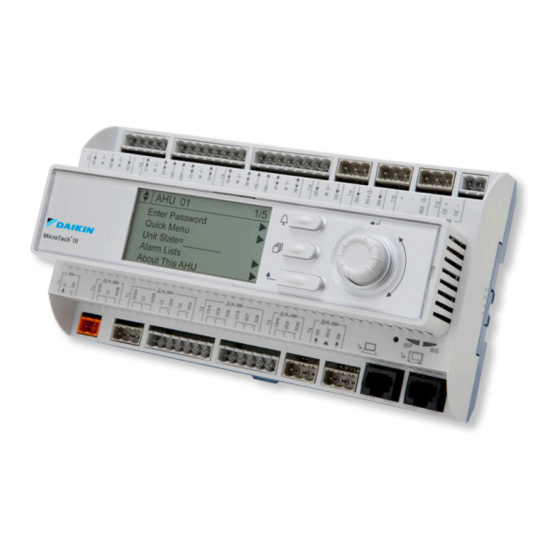
Microtech iii series controller for commercial rooftop systems, applied rooftop systems and self-contained
air conditioners
Hide thumbs
Also See for DPS:
- Installation and maintenance manual (160 pages) ,
- Installation manual (6 pages) ,
- Installation and maintenance manual (46 pages)
Table of Contents
Advertisement
Advertisement
Table of Contents


Need help?
Do you have a question about the DPS and is the answer not in the manual?
Questions and answers