Daikin MicroTech II Installation And Maintenance Manual
Applied rooftop unit controller
Hide thumbs
Also See for MicroTech II:
- Operation and maintenance manual (44 pages) ,
- Installation and maintenance manual (104 pages) ,
- Installation and maintenance manual (24 pages)
Table of Contents
Advertisement
MicroTech® II
Applied Rooftop Unit Controller
•
© 2004 Daikin Applied
Installation and Maintenance
Used with Daikin models: RPS, RFS, RCS, RDT, RPR, RFR, RPE,
RDE, RCE, RDS, RAR & RAH
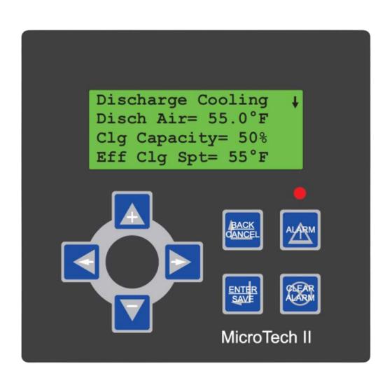
Discharge Cooling
Disch Air= 55.0°F
Clg Capacity= 50%
Eff Clg Spt= 55°F
IM 696-3
Group: Applied Systems
Part Number: IM 696
Date: December 2004
Advertisement
Table of Contents
Troubleshooting

Subscribe to Our Youtube Channel
Related Manuals for Daikin MicroTech II


Summary of Contents for Daikin MicroTech II
- Page 1 Part Number: IM 696 Date: December 2004 MicroTech® II Applied Rooftop Unit Controller • Used with Daikin models: RPS, RFS, RCS, RDT, RPR, RFR, RPE, RDE, RCE, RDS, RAR & RAH Discharge Cooling Disch Air= 55.0°F Clg Capacity= 50% Eff Clg Spt= 55°F...
-
Page 2: Table Of Contents
Manual Cooling and Heating Enable ....19 Daikin and MicroTech II are registered trademarks of Daikin Applied . Microsoft is a registered trademark of Microsoft Corporation. -
Page 3: Introduction
Table 2. Extreme temperature can damage system components. Table 1: Program-specific unit operation literature This MicroTech II controller is designed to operate in ambient Rooftop unit control Operation manual bulletin temperatures from –40°F to 158°F. It can be stored in ambient... -
Page 4: General Description
General Description General Description The MicroTech II Applied Rooftop Unit Controller is a Comfort Controller (SCC) and L Discharge Air microprocessor-based controller designed to provide Controller (DAC). sophisticated control of Daikin RoofPak® applied rooftop Component Data units. In addition to providing normal temperature, static... - Page 5 General Description Figure 2: Main control panel, RPS/RFS/RPR/RDT 45 to 75C and RAH/RAR 47C Figure 3: Main control panel, RPS/RFS/RPR/RDT 80 to 135C and RAH/RAR 77C Daikin IM 696-4...
-
Page 6: Main Control Board (Mcb)
Figure 4: Main control board Binary inputs terminal blocks Power supply terminal Binary outputs terminal block Analog inputs terminal block BACnet/IP BACnet MS/TP RJ-48 jack communication (RS485) or L module communications ORKS communication terminal block module Daikin IM 696-4... -
Page 7: Analog Inputs Terminal Blocks
BO16 on the sixth. it to the board. The MicroTech II Applied Rooftop Unit Each binary output has three terminals. The terminals for BO1 Controller meets the requirements of ANSI/AHRAE 135-2001... -
Page 8: Bacnet Ms/Tp Communications Module
BACnet Master Slave/Token Passing (MS/TP) and maintenance bulletin IM 702, MicroTech II Applied protocol with a conformance level of 3. The MicroTech II Rooftop Controller and Self-Contained Unit Controller Applied Rooftop Unit Controller meets the requirements of Communication Modules. -
Page 9: Rs-232 Connection Port
RS-232 Connection Port Main Control Board LEDs A PC loaded with MicroTech II Service Tool software can be There are a number of LEDs in various locations on the MCB. connected directly or via a telephone modem to the RS-232 These LEDs consist of three groupings. -
Page 10: Auxiliary Control Boards (Ccb1, Ccb2, Ehb1, And Erb1)
(RDS or RAH) equipped with a DX communication bus. Figure 6: Auxiliary control board (CCB1 board shown) Binary inputs terminal block Binary outputs (RS485) terminal block communications terminal block Analog inputs terminal block Daikin IM 696-4... -
Page 11: Analog Inputs Terminal Block (J8)
Table 4. If the switches are not set as load current from all triacs not to exceed 2.8 A, TBV). indicated, the MCB will not communicate correctly with the board and it will not function properly. Daikin IM 696-4... -
Page 12: Auxiliary Control Boards (Ccb1, Ccb2, Gcb1, Ehb1, And Erb1) Output Relays
“Getting Started” section of the applicable operation “remote” LED is OFF) or that remote keypad is physically manual (Refer to Table 1 on page 1). disconnected. If the local unit keypad/display is blank, assume that the remote keypad display is enabled. Daikin IM 696-4... -
Page 13: Temperature Sensors
Pressure Transducers equipped with face and bypass (F&BP) dampers, a spring- The MicroTech II controller uses 0 to 5" w.c., 1 to 6 VDC return, two-position end-of-cycle (EOC) valve is used to static pressure transducers for measuring duct static pressure. -
Page 14: Field Wiring
Fan Operation Output Below are descriptions of the various options and features that may require field wiring to the MicroTech II controller. Refer The Fan Operation Output (MCB-B03) supplies 24 VAC to to the job plans and specifications and the as-built wiring terminal 116 on the field terminal block (TB2) when the output schematics. -
Page 15: Vav Box Output
“Auxiliary VFD control” on thermostat control and drive the VAV boxes fully open when page 48. heating is required. If necessary, the MicroTech II controller energizes the fans for night setback and morning warm-up CAUTION heating operation. -
Page 16: Units With Modulating Heat
MWU, or Heating), the VAV Box Output is in the OFF (or with a MicroTech II controller. A zone temperature sensor heat) position (field-installed pilot relay de-energized) (ZNT1) is optional for all rooftop units except for the 100% switching the VAV boxes into heating operation. -
Page 17: Zone Sensor With Remote Set Point Adjustment
Zone Sensor with Remote Set Point Adjustment Figure 9. Zone sensor with tenant override and remote set point adjustment The standard MicroTech II room temperature sensor package equipped with a set point adjustment potentiometer is available to use with CAV-ZTC (SCC) units. This sensor package also includes a tenant override button. -
Page 18: External Discharge Air Reset Signal
Figure 16 on page 38 for wiring operation. The device or system providing external reset signal termination details. must be connected to the MicroTech II controller chassis, or it must be providing an isolated output. If not, condition the signal CAUTION with a signal isolator. -
Page 19: Field Valve Actuator Feedback
MCB-AI11. Refer to the unit wiring diagrams for wiring termination details. When the MicroTech II controller is interfaced with a field supplied hot water, steam, or chilled water valve actuator, a If the field-supplied feedback signal is 0–500 ohms, the... -
Page 20: Humidity Sensors
Note – The output select jumper (J1) on the sensor must be in the 0–5 VDC position. The TEMP terminals on the When the MicroTech II controller is configured for constant sensor are not used (see Figure 10 or Figure 11 on volume zone temperature control (SCC), a dehumidification page 18). -
Page 21: Humidity Sensor-Discharge Air Control (Dac) Unit
Figure 16 on page 38 (DAC units) or Figure 17 on page 41 For information on setting internal and network controller (SCC units) for wiring termination details. schedules, refer to the “Scheduling” section in the applicable operation manual (refer to Table 1 on page 1). Daikin IM 696-4... -
Page 22: Miscellaneous Output Signals
(refer to Table 1 on page 1). Ground Fan operation (airflow indication) Airflow present Dirty filter indication Filters dirty Heat alarm detected (gas heat flame Alarm failure) Freezestat (freeze condition Normal detected) Smoke (smoke detected) Normal Daikin IM 696-4... -
Page 23: Service Information
Refer to Table 7 on page 22 (DAC units) and Table 8 on page 22 (SCC units) for a description of all the analog inputs including the correct jumper positions. Daikin IM 696-4... - Page 24 Some older units are equipped with a 0-500W (2-wire) resistance feedback signal. In this case the analog input jumper must be in the 1-RTD position, the corresponding input switch must be in the T (OFF) position and the Feedback= parameter in the Economizer Setup, Heating Setup or Chilled Water Setup menu (as applicable) must be set to “2 Wire.” Daikin IM 696-4...
-
Page 25: Analog Inputs-Auxiliary Control Boards (Ccb1, Ccb2, Gcb1, Ehb1 & Erb1)
MCB-BI14 Duct hi limit Normal MCB-BI15 Not used — MCB-BI16 Not used — a. Not used on 100% outdoor air units. b. Applicable only on VAV units configured for “fan tracking” return fan control. c. Applicable on VAV units only. Daikin IM 696-4... -
Page 26: Controller Outputs
24 VAC pilot relay in the unit. Refer to Table 13 on page 25 for the correct jumper position for all the standard binary outputs. Daikin IM 696-4... - Page 27 BO9 and BO10 either modulate the heating value or the face and bypass dampers. If the unit is equipped with multiple stage electric heat, output BO11 provides a signal to the auxiliary electric heat control board (EHB1) to enable heating operation. Daikin IM 696-4...
-
Page 28: Binary Outputs-Auxiliary Control Boards (Ccb1, Ccb2, Gcb1, Ehb1 & Erb1)
Circuit #2 is turned on while the small compressor in Circuit evaporative condenser. Output is energized to open valve. #1 is turned off. When a further capacity increase is required, the small compressor in Circuit #1 is turned on while the large Daikin IM 696-4... - Page 29 If the the most run hours is turned off. other circuit is enabled, it acts as the “Lead” and the circuit capacity is controlled using the Lead Circuit Loading. Daikin IM 696-4...
- Page 30 This output is not used on unit equipped with an evaporative condenser and a VFD controlling the first condenser fan on each circuit (Condenser Fan # 11 and # 21). The VFD controlling these fans is started and stopped and modulated via RS-485 communications with the main control board. Daikin IM 696-4...
- Page 31 This output is not used on unit equipped with an evaporative condenser and a VFD controlling the first condenser fan on each circuit (Condenser Fan # 11 and # 21). The VFD controlling these fans is started and stopped and modulated via RS-485 communications with the main control board. Daikin IM 696-4...
- Page 32 The VFD controlling these fans is started and stopped and modulated via RS-485 communications with the main control board. e. This output is used to open a sump dump valve on units equipped with an evaporative condenser. Output is energized to open valve. Daikin IM 696-4...
-
Page 33: Gcb1 (Rds & Rah)
Service Information GCB1 (RDS & RAH) MicroTech II controller but rather by the condensing unit control system. For RDS and RAH model air handling units interfaced with generic condensing units, the cooling stages are controlled by EHB1 an auxiliary control board loaded with special generic When a unit is equipped with a multiple stage electric heater condensing unit control software. -
Page 34: Eerb1
MCB, it must be “configured” for the specific control application. This consists of setting the value of 20 The MicroTech II control system code is made up of up to four configuration variables within the MCB. These variables different software components. -
Page 35: Main Control Board (Mcb) Data Archiving
Max heat rise Three digits (default = 100) 0 Constant volume Discharge fan 1 Variable inlet vanes type 2 Variable freq drive 0 Constant volume 1 Variable inlet vanes Return fan 2 Variable freq drive type 3 No Return fan 4 Propeller exhaust Daikin IM 696-4... -
Page 36: Typical Wiring Diagrams
Main control box CB60 Circuit breaker, energy Main control box GFR4 Ground fault relay, condenser Condenser control box recovery wheel GFS4 Ground fault sensor, Condenser control box CCB1, 2 Compressor control boards, Main control box condenser refrig. circuits Daikin IM 696-4... - Page 37 Main control box Bypass, Return Fan PS1, 2 Pumpdown switches, refrig Main/cond. control box M41–50 Contactor, electric heat (bot. Electric heat box circuits bank) Pumpdown switch, RFS only Main control box PVM1, 2 Phase voltage monitor Main control box Daikin IM 696-4...
- Page 38 Receptacle, condenser box Condenser control box convenience outlet, field REC3 Receptacle, field power, 115V Discharge bulkhead Terminal block, 115V conv. Condenser control box outlet, RCS, field REC10– Receptacle, cabinet sections Cabinet sections TB11 Terminal block, heat Heat control box Daikin IM 696-4...
- Page 39 Water level, sump, low water Evap. condenser section ZNT1 Zone temp. sensor, setback Field installed General Notes Field wiring Factory wiring Shielded wire/cable Main control box terminals Auxilliary box terminals Field terminals Plug connector 200/ H200 Wire/harness number Wire nut/ID Daikin IM 696-4...
- Page 40 Typical Wiring Diagrams Figure 16: VAV control inputs (DAC) Daikin IM 696-4...
- Page 41 Typical Wiring Diagrams Figure 16: VAV control inputs (DAC), continued Daikin IM 696-4...
- Page 42 Typical Wiring Diagrams Figure 17: Constant volume control inputs (SCC) Daikin IM 696-4...
- Page 43 Typical Wiring Diagrams Figure 17: Constant volume control inputs (SCC), continued Daikin IM 696-4...
- Page 44 Typical Wiring Diagrams Figure 18: Control actuator outputs (constant volume RPS with hot water or steam heat with economizer) Daikin IM 696-4...
- Page 45 Typical Wiring Diagrams Figure 18: Control actuator outputs (constant volume RPS with hot water or steam heat with economizer), continued H343-9 Daikin IM 696-4...
- Page 46 Typical Wiring Diagrams Figure 19: Condensing section control, RPS 60 (with scroll compressors) Daikin IM 696-4...
- Page 47 Typical Wiring Diagrams Figure 19: Condensing section control, RPS 60 (with scroll compressors), continued Daikin IM 696-4...
- Page 48 Typical Wiring Diagrams Figure 20: Condensing section control, RPS 135 (with reciprocating compressors) Daikin IM 696-4...
- Page 49 Typical Wiring Diagrams Figure 21: Condensing section control, RPS 135 (with reciprocating compressors), continued Daikin IM 696-4...
- Page 50 Typical Wiring Diagrams Figure 22: Auxiliary VFD control Daikin IM 696-4...
- Page 51 Typical Wiring Diagrams Figure 22: Auxiliary VFD control Daikin IM 696-4...
- Page 52 Typical Wiring Diagrams Figure 23: Modulating gas heat control (standard mod) Daikin IM 696-4...
- Page 53 Typical Wiring Diagrams Figure 23: Modulating gas heat control (standard mod), continued Daikin IM 696-4...
- Page 54 Typical Wiring Diagrams Figure 24: Multistage electric heat control (4 stage) Daikin IM 696-4...
- Page 55 Typical Wiring Diagrams Figure 24: Multistage electric heat control (4 stage), continued Daikin IM 696-4...
- Page 56 Typical Wiring Diagrams Figure 25: Energy recovery wheel control Daikin IM 696-4...
- Page 57 Typical Wiring Diagrams Figure 25: Energy recovery wheel control , continued H957-7 H957-9 H957-12 H957-8 Daikin IM 696-4...
- Page 58 (OPEN OUTPUT) (OPEN OUTPUT) (OPEN OUTPUT) (OPEN OUTPUT) (OPEN OUTPUT) BINARY OUTPUT ELEC. RATINGS 277V, 5A RESISTIVE 120V, 1/10HP, 3FLA, 18LRA, 100VA PILOT DUTY 240V, 1/4HP, 2.9FLA, 17.4LRA, 250VA PILOT DUTY 277V, 1/3HP, 2.98FLA, 17.88LRA, 300VA PILOT DUTY Daikin IM 696-4...
- Page 59 431A Figure 27: Light and receptacle power FIELD SUPPLIED 115V/60/1 REC1 1003A 1003B 1004B G1004 1005A 1005B LT10 PL31 H1006-1 PL31 H775 H1006-2 REC10 H775 H776 G1009 LT11 PL32 PL32 H1010-1 H775 H1010-2 REC11 H775 H776 G1012 Daikin IM 696-4...
-
Page 60: Test Procedures
At this time, all the MCB control parameter settings When troubleshooting the various MicroTech II components, it are archived to a file stored in the MCB FLASH memory. may be necessary to remove power to the controller by If the MCB is powered up with a low or defective battery (or opening system switch S1 in the main control panel. - Page 61 MCB battery condition. defective, this period lasts approximately 90 seconds during which previously archived control parameter data is restored to the controller. Refer to “Main Control Board (MCB) Data Archiving” on page 33. Daikin IM 696-4...
-
Page 62: Mcb Led Startup Error Codes
L expansion main/boot port port startup config. byte byte port port (optional) port RS-485 bus port RS-232 port IP port MCB error Blinking Blinking Blinking Blinking Blinking BI-1 BI-2 BI-3 BI-4 BI-5 BI-6 BI-7 BI-8 Daikin IM 696-4... -
Page 63: Battery Test
After determining the existence of an optional IP is unpredictable. Daikin recommends downloading the startup communication module, the MCB performs a series of read/ code again. If this is not possible or ineffective, replace the write tests on critical registers of the IP processor. -
Page 64: Troubleshooting Auxiliary Control Boards (Ccb1, Ccb2, Gcb1, Ehb1 And Erb1)
= OK normally or XRAM if external RAM test failed entire control system using the S1 system switch. If this has been done and the problem persists, proceed to Step ccc = OK normally or ROM if ROM checksum does not match b below. stored checksum Daikin IM 696-4... -
Page 65: Troubleshooting Temperature Sensors
68 (20) 77 (25) 1035 Troubleshooting Temperature Sensors 86 (30) 1074 The MicroTech II temperature sensor consists of a positive 95 (35) 1113 temperature coefficient (PTC) silicon sensing element. The 104 (40) 1153 resistance of this sensor increases with increasing temperature. -
Page 66: Troubleshooting Communications Modules
Applied Rooftop Unit Controller and Self-Contained Unit Controller BACnet Communications Module—BACnet/IP. For details regarding BACnet protocol data, refer to engineering data document, ED 15060, MicroTech II Applied Rooftop Unit Controller Protocol Information. BACnet MS/TP Module For a detailed description and troubleshooting information... -
Page 67: Troubleshooting Pressure Transducers
Note – If the suspect sensor is measuring duct static pressure, verify that the high and low pressure taps are properly installed. An improper pressure tap installation can cause severe fluctuations in the sensed pressure. Refer Daikin IM 696-4... -
Page 68: Parts List
Below is a partial list of applied rooftop unit replacement parts. Contact a local sales representative for additional information Table 26: Component Description Daikin part number designation Main control board 060006101 CCB1 Auxiliary cooling control board (DX Circuit #1 or generic condenser) - Page 69 Daikin IM 696-4...
- Page 70 Daikin Training and Development Now that you have made an investment in modern, efficient Daikin equipment, its care should be a high priority. For training information on all Daikin HVAC products, please visit us at www.DaikinApplied.com and click on training, or call 540-248-9646 and ask for the Training Department.
Need help?
Do you have a question about the MicroTech II and is the answer not in the manual?
Questions and answers