Daikin MICROTECH III Operating Manual
Water-cooled screw chiller
Hide thumbs
Also See for MICROTECH III:
- Operation manuals (144 pages) ,
- Sales and engineering data sheet (68 pages) ,
- Operation manual (52 pages)

Related Manuals for Daikin MICROTECH III


Summary of Contents for Daikin MICROTECH III
- Page 1 Date 05/2021 Supersedes D–EOMWC00A07-16_01EN CONTROL PANEL OPERATING MANUAL D–EOMWC00A07-16_02EN WATER-COOLED SCREW CHILLER MICROTECH III and MICROTECH 4...
-
Page 2: Table Of Contents
Table of Contents INTRODUCTION ............................ 4 CONTROLLER OPERATING LIMITS ....................5 CONTROLLER FEATURES ........................5 GENERAL DESCRIPTION........................6 ........................6 ENERAL ESCRIPTION ....................... 6 PERATION OMMANDS AYOUT ....................... 7 ONTROLLER ESCRIPTION ......................10 ONTROL NETWORK DETAILS SEQUENCE OF OPERATION ......................11 CONTROLLER OPERATION .......................14 ......................14 ICRO NPUTS... - Page 3 10.6 ..........................43 VENTS 10.7 ..........................46 IRCUIT LARMS 10.8 ......................47 IRCUIT APID LARMS 10.9 ....................57 IRCUIT UMPDOWN LARMS 10.10 ..........................60 IRCUIT VENTS BASIC CONTROL SYSTEM DIAGNOSTIC ..................63 USING THE CONTROLLER .........................65 12.2 ............................66 AVIGATING OPTIONAL REMOTE USER INTERFACE....................73 EMBEDDED WEB INTERFACE ......................75 CONTROLLER MAINTENANCE ......................76 ICM AND MASTER/SLAVE ........................76 3/77...
-
Page 4: Introduction
This manual provides setup, operating, troubleshooting and maintenance information for the DAIKIN Water Cooled Chillers listed below with 1, 2 and 3 circuits using Microtech III and Microtech 4 Controllers (Microtech in the following sections to be intended as the two mentioned controllers; this manual does not apply to the previous Microtech controllers). -
Page 5: Controller Operating Limits
CONTROLLER OPERATING LIMITS Operation (IEC 721-3-3): • Temperature -40...+70 °C • Restriction LCD -20… +60 °C • Restriction Process-Bus -25….+70 °C • Humidity < 90 % r.h (no condensation) • Air pressure min. 700 hPa, corresponding to max. 3,000 m above sea level Transport(IEC 721-3-2): •... -
Page 6: General Description
GENERAL DESCRIPTION The control panel is located on the front of the unit at the compressor end. There are three doors. The control panel is behind to left-hand door. The power panel is behind the middle and right-hand doors. General Description The MicroTech control system consists of a microprocessor-based controller and a number of extension modules, which vary depending on the unit size and conformation. -
Page 7: Controller Description
Unit On/Off Switch #2 Compressor On/Off Switch #1 Compressor On/Off Switch Unit On/Off Switch Heat Pump Switch #1 Compressor On/Off Switch Figure 2, Operation Commands Controller Description 4.3.1 Hardware Structure The MicroTech control system for water cooled screw chillers consists of a main unit controller with a number of extension I/O modules attached depending on the chiller size and configuration. - Page 8 Remote Operator Interface MicroTech III Unit Controller BACnet/IP BACnet/ MSTP Communication Cards MODbus Extension I/O Modules Figure 3, hardware structure 4.3.2 System Architecture The overall controls architecture uses the following: • One Microtech main controller • I/O extension modules as needed depending on the configuration of the unit •...
- Page 9 Figure 4, System Architecture 9/77 Operation Manual D–EOMWC00A07-16_02EN...
-
Page 10: Control Network Details
This will be done in the factory as part of the unit manufacturing or in the field by asking for the activation code as a Spare part. Because these features may conflict with others (for example Bacnet IP and Daikin on Site). -
Page 11: Sequence Of Operation
SEQUENCE OF OPERATION Figure 5, Unit Sequence of Operation (see Figure 9 for circuit sequence of operation) AWS Chiller Sequence of Operation in Cool Mode Unit power up Unit in Off state The chiller may be disabled via the unit switch, the remote switch, the keypad enable setting, or the BAS network. - Page 12 The first circuit to start is generally the available circuit with the least number of Start first circuit. starts. This circuit will go through its start sequence at this point. The first circuit will be loaded and unloaded as needed in an attempt to satisfy the Load/unload as needed to load by controlling LWT to the Active Setpoint.
- Page 13 Figure 6, Circuit Sequence of Operation AWS Sequence of Operation - Circuits Unit power up When the circuit is in the Off state the EXV is closed, compressor is off, and all fans Circuit is in Off state are off. The circuit must be enabled before it can run.
-
Page 14: Controller Operation
CONTROLLER OPERATION MicroTech Inputs/Outputs The chiller may be equipped with one up to three compressors. 6.1.1 Analog Inputs Description Signal Source Expected Range -50°C – 120°C Evaporator Entering Water Temp NTC Thermister (10K@25°C) -50°C – 120°C Evaporator Leaving Water Temp NTC Thermister (10K@25°C) -50°C –... -
Page 15: I/O Exv Circuit #1 To #3
Motor Protection PTC Thermistor 6.2.2 Analog Outputs Description Output Signal Range Not Needed 6.2.3 Digital Inputs Description Signal Off Signal On Starter Fault Fault No fault Circuit Switch Circuit Off Circuit On High Pressure Switch Fault No fault 6.2.4 Digital Outputs Description Output Off Output On... -
Page 16: Extension I/O Fan Module Circuit #2
Extension I/O Fan Module Circuit #2 6.4.1 Digital Outputs Description Signal source Output On Circuit #2 Fan Step #1 Fan Off Fan On Fan Off Fan On Fan Off Fan On Circuit #2 Fan Step #2 Fan Off Fan On Fan Off Fan On Circuit #2 Fan Step #3 Fan Off Fan On... -
Page 17: Unit Functions
UNIT FUNCTIONS Calculations 7.1.1 LWT Slope LWT slope is calculated such that the slope represents the change in LWT over a time frame of one minute with at least five samples per minute for both evaporator and condenser. 7.1.2 Pulldown Rate The slope value calculated above will be a negative value as the water temperature is dropping. -
Page 18: Unit Control States
The Available Modes Set Point must only be changed when the unit switch is off. This is to avoid changing modes of operation inadvertently while the chiller is running. Unit Mode is set according to the following table. NOTE: An “x” indicates that the value is ignored. Control Source Mode HP Switch... -
Page 19: Unit Status
Unit Status The displayed unit status is determined by the conditions in the following table: Enum Status Conditions Auto Unit State = Auto Off:Ice Mode Timer Unit State = Off, Unit Mode = Ice, and Ice Delay = Active Off:All Cir Disabled Unit State = Off and all compressors unavailable Off:Unit Alarm Unit State = Off and Unit Alarm active... -
Page 20: Condenser Pump Control
7.8.1 Pump Selection The pump output used is determined by the Evap Pump Control set point. This setting allows the following configurations: • #1 only – Pump 1 will always be used • #2 only – Pump 2 will always be used •... - Page 21 7.10.1 Cond In/Cond Out condensation control If the Condensation Control Value Set Point is set to Cond In or Cond Out options, then Tower fan #1..4 control is enabled for the unit. According to Tower fan #1..4 set point and differential default values listed in the Unit Set Points table, the following graph summarizes the activation and deactivation conditions for Towers fan.
-
Page 22: Leaving Water Temperature (Lwt) Reset
7.10.2 Pressure condensation control Refer to Circuit Functions. 7.11 Leaving Water Temperature (LWT) Reset 7.11.1 LWT Target The LWT Target varies based on settings and inputs and is selected as follows: Control Source Mode Available Modes Base LWT Target Set Point Input Switch Request... -
Page 23: Unit Capacity Control
Reset varies from 0 to Max Reset set point as the Evaporator EWT – LWT (Evap delta t) varies from the Start Reset Delta T set-point to 0. 7.11.3 4-20 mA External Signal Reset The Active Leaving Water variable is adjusted by the 4 to 20 mA reset analog input. Parameters used: Cool LWT set point Max Reset set point... - Page 24 Light Load Stage Down in Cool Mode When multiple compressors are running, one will shut down if all running compressors are at a capacity lower than the Load Stage Down set point and the evaporator LWT is less than the target plus the Stage Up Delta T set point. A minimum amount of time will pass between compressors stopping as a result of this logic, which is defined by the Stage Down Delay set point.
-
Page 25: Unit Capacity Overrides
7.12.6 Load/Unload Sequence This section defines which compressor is the next one to load or unload. Next To Load The next compressor to load meets the following requirements: Lowest capacity of the running compressors that can load up • if capacities are equal, it must have the highest sequence number of the compressors that are running •... -
Page 26: Energy Saving Mode
The Daikin on Site(DoS) page can be accessed navigating through Main Menu → View/Set Unit → Daikin On Site. In order to use the DoS utility, the customer has to communicate the Serial Number to Daikin company and subscribe to the DoS service. -
Page 27: Circuit Functions
Start Start the connection to DoS Comm State Connection to DoS is off IPErr Connection to DoS cannot be established Connected Connection to DoS is established and working Remote Update Enable Enable the Remote update option Disable Disable the Remote update option CIRCUIT FUNCTIONS Calculations 8.1.1... -
Page 28: Circuit Control Logic
Circuit Control Logic 8.2.1 Circuit Availability A circuit is available to start if the following conditions are true: • Circuit switch is closed • No circuit alarms are active • Circuit Mode set point is set to Enable • BAS Circuit Mode set point is set to Auto •... -
Page 29: Circuit Status
Circuit Status The displayed circuit status is determined by the conditions in the following table: Enum Status Conditions Off:Ready Circuit is ready to start when needed. Off:Stage Up Delay Circuit is off and cannot start due to stage up delay. Off:Cycle Timer Circuit is off and cannot start due to active cycle timer. - Page 30 Model Name plate F3AS HSA192 F3AL HSA204 F3BS HSA215 F3BL HSA232 F4AS HSA241 F4AL HSA263 The required capacity is achieved by controlling one modulating slide and one non-modulating slide. The modulating slide can control 10% to 50% of the total compressor capacity, infinitely variable. The non-modulating slide can control either 0% or 50% of the total compressor capacity.
-
Page 31: Pressure Condensation Control
Capacity Overrides – Limits of Operation The following conditions override automatic capacity control when the chiller is in COOL mode. These overrides keep the circuit from entering a condition in which it is not designed to run. Low Evaporator Pressure If the Low Evaporator Pressure Hold event is triggered, the compressor will not be allowed to increase in capacity. -
Page 32: Exv Control
If the Condensation Control Value Set Point is set to Press option and Cond Aout type Set Point is set to Vfd option, a 0 - 10V signal is also enabled for the circuit to regulate a modulating condensation device by mean of a PID controller. According to Vfd default values listed in the Circuit Set Points table, the following graph represents the modulating signal behavior in case of a control supposed to be purely proportional. -
Page 33: Liquid Injection
Transitions Between Control States Whenever EXV control changes between Startup Operation, Normal Operation, or Manual Control, the transition is smoothed by gradually changing the EXV position rather than changing all at once. This transition prevents the circuit from becoming unstable and resulting in a shutdown due to alarm trip. Liquid Injection Liquid injection is activated when the circuit is in a run state and the discharge temperature rises above the Liquid Injecti on Activation set point. -
Page 34: Software Options
4.15.1. If there is no enough time to ask for a Password to Daikin Personnel (ex. an expected failure of the controller), a set o f Free Limited Password is provided, in order not to interrupt the machine’s working. - Page 35 553489691893 – 3 Months Duration • 411486702597 – 1 Month Duration • 084430952438 – 1 Month Duration It gives the customer the time enough to contact Daikin Service and insert a new unlimited password. Parameter Specific Status Description 553489691893 Activate the Option Set for 3 Months.
-
Page 36: Alarms And Events
ALARMS AND EVENTS Situations may arise that require some action from the chiller or that should be logged for future reference. A condition that requires a shutdown and/or lockout is an alarm. Alarms may cause a normal stop (with pumpdown) or a rapid stop. Most alarms require manual reset, but some reset automatically when the alarm condition is corrected. -
Page 37: Unit Rapid Stop Alarms
10.4 Unit Rapid Stop Alarms 10.4.1 Phase Volts Loss/GFP Fault This alarm is generated in case of problems with the power supply to the chiller. Resolution of this fault requires a direct intervention on the power supply of this unit. Direct intervention on the power supply can cause electrocution, burns or even death. - Page 38 10.4.3 Evaporator Flow Loss This alarm is generated in case of flow loss to the chiller to protect the machine against Mechanical High Pressure trips. Symptom Cause Solution Unit status is Off. No water flow sensed for 3 minutes Check the water pump filler and the All circuits are stopped immediately.
- Page 39 10.4.5 Evaporator Water Freeze Protect This alarm is generated to indicate that the water temperature (entering or leaving) has dropped below a safety limit. Control tries to protect the heat exchanger starting the pump and letting the water circulate. Symptom Cause Solution Unit status is Off.
- Page 40 10.4.7 Leaving Evaporator Water Temperature Sensor Fault This alarm is generated any time that the input resistance is out of an acceptable range. Symptom Cause Solution Unit status is Off. Sensor is broken. Check for sensor integrity. according All circuits are stopped with a normal table and allowed kOhm (k ) range.
-
Page 41: Unit Pumpdown Stop Alarms
10.4.10 Emergency Stop Alarm This alarm is generated any time the Emergency Stop button is activated. Before resetting the Emergency Stop button please verify that the harmful condition has been removed. Symptom Cause Solution Unit status is Off. Emergency stop button has been Turning counterclockwise the All circuits are stopped immediately. - Page 42 10.5.2 Condenser Entering Water Temperature Sensor Fault This alarm is generated any time the input resistance is out of an acceptable range. Symptom Cause Solution Unit status is Off. Sensor is broken. Check for sensor integrity. according All circuits are stopped with a normal table and allowed kOhm (k ) range.
-
Page 43: Unit Events
Symptom Cause Solution Unit status is Off. Module has no power supply Check the power supply from the All circuits are stopped immediately. connector on the side of the module. Bell icon is moving on controller’s Check if LEDs are both green. display. - Page 44 10.6.2 External Event This alarm indicates that a device, whose operation is linked with this machine, is reporting a problem on the dedicated input. Symptom Cause Solution Unit status is Run. There is an external event that has Check for reasons of external event Bell icon is moving on controller’s caused the opening, for at least 5 and if it can be a potential problem...
- Page 45 10.6.5 Bad Current Limit Input This alarm is generated when the Current Limit option has been enabled and the input to the controller is out of the admitted range. Symptom Cause Solution Unit status is Run. Flexible current limit input out of Check for values of input signal to Bell icon is moving on controller’s range.
-
Page 46: Circuit Alarms
10.6.7 Bad Leaving Water Temperature Reset Input This alarm is generated when the Setpoint Reset option has been enabled and the input to the controller is out of the admitted range. Symptom Cause Solution Unit status is Run. LWT reset input signal is out of range. Check for values of input signal to Bell icon is moving on controller’s For this warning out of range is a... -
Page 47: Circuit Rapid Stop Alarms
10.8 Circuit Rapid Stop Alarms 10.8.1 Low Evaporator Pressure This alarm is generated in case the evaporating pressure drops below the Low Pressure Unload and the control is not able to compensate to this condition. Symptom Cause Solution Circuit status is Off. Transitory condition like a fan staging Wait until the condition is recovered The compressor does not load... - Page 48 10.8.2 Low Pressure Start Fail This alarm indicates that at the compressor start the evaporating pressure or condensing pressure is below a minimum fixed limit at compressor start. Symptom Cause Solution Circuit status is Off. Ambient temperature is too low Check the operating envelope for this The circuit is stopped.
- Page 49 10.8.3 High Condenser Pressure This alarm is generated in case the Condensing saturated temperature rise above the Maximum condensing saturated temperature and the control is not able to compensate to this condition. The maximum condenser saturated temperature is 68.5°C but it can decrease when the evaporator saturated temperature become negative. In case units operating at high condenser water temperature and with HT option, if the Condensing saturated temperature exceeds the Maximum condenser saturated temperature, the circuit is only switched off without any notification on the screen as this condition is considered acceptable in this range of operation.
- Page 50 10.8.4 Mechanical High Pressure Switch This alarm is generated when the condenser pressure rises above the mechanical high pressure limit causing this device to open the power supply to all the auxiliary relays. This causes an immediate shutdown of compressor and all the other actuators in this circuit.
- Page 51 10.8.5 High Discharge Temperature This alarm indicates that the temperature at the discharge port of the compressor exceeded a maximum limit which may cause damages to the mechanical parts of the compressor. When this alarm occurs compressor’s crankcase and discharge pipes may become very hot. Be careful when getting in contact with the compressor and discharge pipes in this condition.
- Page 52 10.8.7 Compressor Starter Fault This alarm is generated any time starter fault input is open or if the compressor has been running for at least 14 seconds and starter fault input is open Symptom Cause Solution Circuit status is OFF. Contactors may be broken or weared Check if contactors operate Bell icon is moving on controller’s...
- Page 53 10.8.9 No Pressure Change After Start This alarm indicates that the compressor is not able to start or to create a certain minimum variation of the evaporating or condensing pressures after start. Symptom Cause Solution Circuit status is Off. Compressor cannot start. Check if the start signal is properly The circuit is stopped.
- Page 54 10.8.11 CC Comm Failure # This alarm is generated in case of communication problems with the CCx module. Symptom Cause Solution Circuit status is Off. Module has no power supply Check the power supply from the All circuits are stopped immediately. connector on the side of the module.
- Page 55 10.8.13 EEXV Comm Failure # This alarm is generated in case of communication problems with the EEXVx module. Symptom Cause Solution Circuit status is Off. Module has no power supply Check the power supply from the All circuits are stopped immediately. connector on the side of the module.
- Page 56 10.8.15 Condenser Pressure Sensor Fault This alarm indicates that the condensing pressure transducer is not operating properly. Symptom Cause Solution Circuit status is Off. Sensor is broken. Check for sensor integrity. Check The circuit is stopped. correct sensors operation Bell icon is moving on controller’s according information about mVolt (mV) range related to pressure display.
-
Page 57: Circuit Pumpdown Stop Alarms
10.8.17 Maximum Number of Restart Alarm (condenserless units only) This alarm indicates that for three consecutive times after the compressor start the evaporating pressure is under a minimum limit for too much time Symptom Cause Solution Circuit status is Off. Ambient temperature is too low. - Page 58 10.9.2 Low Pressure Ratio This alarm indicates that the ratio between evaporating and condensing pressure is below a limit which depends on compressor speed and guarantees the proper lubrication to compressor. Symptom Cause Solution Circuit status is Off. Compressor is not able to develop the Check fan setpoint and settings, it The circuit is stopped.
- Page 59 10.9.4 Suction Temperature Sensor Fault This alarm is generated to indicate that the sensor is not reading properly. Symptom Cause Solution Circuit status is Off. Sensor is shorted. Check for sensor integrity. The circuit is switched off with the normal shutdown procedure. Check correct sensors operation Bell icon is moving on controller’s according information about kOhm...
-
Page 60: Circuit Events
10.10 Circuit Events The following events limit operation of the circuit in some way as described in the Action Taken column. The occurrence of a circuit event only affects the circuit on which it occurred. Circuit events are logged in the event log on the unit controller. - Page 61 High Condenser Pressure – Hold/Unload 10.10.2 These events are generated to indicate a temporary condition with the condensing pressure above the hold and unload limits. Symptom Cause Solution Circuit status is One or more condenser fans do not Check if fans protections have been Run: High Cond Press operate properly (Condenserless activated.
- Page 62 10.10.3 Failed Pumpdown This event can indicate a wrong operation of the exv that needs to be checked. Symptom Cause Solution Circuit status is Wrong operation of the exv which Check the exv driver to verify that it doesn’t close. Off: Ready can correctly move the valve.
-
Page 63: Basic Control System Diagnostic
BASIC CONTROL SYSTEM DIAGNOSTIC MicroTech controller, extension modules and communication modules are equipped with two status LED (BSP and BUS) to indicate the operational status of the devices. The meaning of the two status LED is indicated below. Controller LED BSP LED BUS LED Mode... - Page 64 Solid Green Ready for Communication. (All Parameter loaded, Neuron configured). Doesn't indicate a communication with other devices. Solid Yellow Startup Solid Red No Communication to Neuron (internal error, could be solved by downloading a new LON application). Flashing Yellow Communication not possible to the Neuron. The Neuron must be configured and set online over the LON Tool.
-
Page 65: Using The Controller
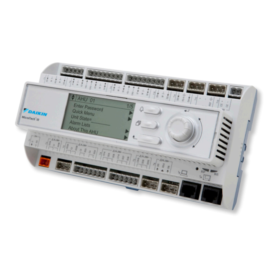
USING THE CONTROLLER 12.1 The Unit Controller Operation Alarm Button Menu Button Navigation Wheel Back Button Display Figure 7, Unit Controller The keypad/display consists of a 5-line by 22 character display, three buttons (keys) and a “push and roll” navigation wheel. There is an Alarm Button, Menu (Home) Button, and a Back Button. -
Page 66: Navigating
This manual includes information relative to the operator level of parameters; data and setpoints necessary for the every day operation of the chiller. There are more extensive menus available for the use of service technicians. 12.2 Navigating When power is applied to the control circuit, the controller screen will be active and display the Home screen, which can also be accessed by pressing the Menu Button The navigating wheel is the only navigating device necessary, although the MENU, ALARM, and BACK buttons can provide shortcuts as explained later. - Page 67 12.2.2 Navigation Mode When the navigation wheel is turned clockwise, the cursor moves to the next line (down) on the p age. When the wheel is turned counter-clockwise the cursor moves to the previous line (up) on the page. The faster the wheel is turned the faster the cursor moves.
- Page 68 A parameter with an “R” is read only; it is giving a value or description of a condition. An “R/W” indicates a read and/or write opportunity; a value can be read or changed (providing the proper password has been entered). Example 1: Check Status, for example -is the unit being controlled locally or by an external network? We are looking for the Unit Control Source Since this a unit status parameter, start at Main Menu and select View/Set Unit and press the wheel to jump to the next set of menus.
- Page 69 Figure 15, Home Page, Main Menu Parameters and Links Home Page View/Set Unit Status/Settings Enter Password Set-Up Continue W/O Password Temperatures Date/Time/Schedules Power Conservation LON Setup Main Menu BACnet IP Setup BACnet MSTP Setup View/Set – Unit ...
- Page 70 Figure 16, Navigation, Part A View/Set Unit Status/Settings Status/Settings (view/set unit)UUnitunitunit) Set-Up Unit Status Temperatures Chiller Enable Condenser Control Source Date/Time/Schedules Next Circuit On Chiller Enable Setpoint - Power Conservation Network LON Setup Chiller Mode Setpoint - ...
- Page 71 Figure 17, Navigation, Part B View/Set Unit Status/Settings Power Conservation (view/set unit) Set-Up Unit Capacity Temperatures Unit Current Condenser Demand Limit Enable Date/Time/Schedules Demand Limit Value Power Conservation Current @ 20mA LON Setup Current Limit Setpoint ...
- Page 72 Figure 18, Navigation, Part C View/Set Unit Status/Settings AWM Setup (view/set unit) Set-Up Apply Changes Temperatures DHCP Condenser Actual IP Address Date/Time/Schedules Actual Mask Power Conservation Actual Gateway LON Setup Given IP Address ...
-
Page 73: Optional Remote User Interface
OPTIONAL REMOTE USER INTERFACE The optional remote user interface is a remote control panel that mimics operation of the controller located on the unit. Up to eight AWS units can be connected to it and selected on the screen. It provides HMI (Human Machine Interface) within a building, the building engineer’s office for example, without going outdoors to the unit. - Page 74 D–EOMWC00A07-16_02EN Operation Manual 74/77...
-
Page 75: Embedded Web Interface
EMBEDDED WEB INTERFACE The MicroTech controller has an embedded web interface that can be used to monitor the unit when connected to a local network. It is possible to configure the IP addressing of the MicroTech as a fixed IP or DHCP depending on the network configuration. -
Page 76: Controller Maintenance
CONTROLLER MAINTENANCE The controller requires to maintain the installed battery. Every two years it’s required to replace the battery. Battery model is: BR2032 and it is produced by many different vendors. To replace the battery remove the plastic cover of the controller display using a screw driver as shown in the following picture: Be careful to avoid damages to the plastic cover. - Page 77 The present publication is drawn up by of information only and does not constitute an offer binding upon Daikin Applied Europe S.p.A.. Daikin Applied Europe S.p.A. has compiled the content of this publication to the best of its knowledge. No express or implied warranty is given for the completeness, accuracy, reliability or fitness for particular purpose of its content, and the products and services presented therein.
Need help?
Do you have a question about the MICROTECH III and is the answer not in the manual?
Questions and answers
is it possible to take backup for microtech controller lll
Yes, a backup can be taken for the Daikin MICROTECH III controller.
This answer is automatically generated
Where can I find the bacnet network objects for daikin chillers microtech 4 series