Table of Contents
Advertisement
Quick Links
Advertisement
Table of Contents

Subscribe to Our Youtube Channel
Summary of Contents for Cambium Networks PTP 650 Series
-
Page 1: User Guide
Cambium PTP 650 Series User Guide System Release 650-01-01... - Page 2 Accuracy While reasonable efforts have been made to assure the accuracy of this document, Cambium Networks assumes no liability resulting from any inaccuracies or omissions in this document, or from use of the information obtained herein. Cambium reserves the right to make changes to any products described...
-
Page 3: Table Of Contents
Contents About This User Guide .......................... 1 Contacting Cambium Networks ....................1 Purpose ............................2 Cross references ..........................2 Feedback ............................2 Important regulatory information......................3 Radar avoidance ..........................3 USA and Canada specific information ..................3 Specific expertise and training required for professional installers ......... 4 Avoidance of weather radars ...................... - Page 4 Contents Typical bridge deployment ......................1-4 Hardware overview ........................1-5 Wireless operation ..........................1-6 Time division duplexing ......................1-6 Link mode optimization ......................1-8 Link symmetry ..........................1-8 OFDM and channel bandwidth ....................1-9 Spectrum management ......................1-9 Adaptive modulation ........................ 1-10 MIMO ............................
- Page 5 Contents Recovery mode .......................... 1-35 Chapter 2: System hardware ......................2-1 Outdoor unit (ODU) ........................... 2-2 ODU description .......................... 2-2 ODU part numbers ........................2-3 ODU mounting brackets ......................2-5 ODU interfaces ..........................2-6 ODU specifications ........................2-7 Power supply units (PSU) ........................2-8 PSU description ...........................
- Page 6 Contents Lightning protection zones ......................3-8 Site grounding system......................3-10 ODU and external antenna location ..................3-10 ODU wind loading ........................3-11 PSU DC power supply....................... 3-12 PSU location ..........................3-12 Drop cable grounding points ....................3-13 LPU location ..........................3-13 Multiple LPUs ..........................
- Page 7 System threshold, output power and link loss ................3-41 Data throughput capacity tables ..................... 3-47 Chapter 4: Legal and regulatory information ................4-1 Cambium Networks end user license agreement ................4-2 Acceptance of this agreement ....................4-2 Definitions ............................ 4-2 Grant of license ........................... 4-2 Conditions of use ........................
- Page 8 Contents Electromagnetic compatibility (EMC) compliance ..............4-23 Human exposure to radio frequency energy ................4-24 Compliance with radio regulations ....................4-27 Type approvals .......................... 4-27 FCC/IC compliance ........................4-29 European Union compliance ....................4-31 Chapter 5: Installation ........................5-1 Safety ..............................5-2 Power lines ..........................
- Page 9 Contents Installing the AC+DC Enhanced Power Injector ..............5-22 Installing an SFP Ethernet interface ....................5-23 Fitting the long cable gland ...................... 5-25 Inserting the SFP module ......................5-26 Connecting the cable ........................ 5-29 Fitting the gland ........................5-30 Removing the cable and SFP module ..................5-31 Installing an Aux Ethernet interface ....................
- Page 10 Contents QoS Configuration page ......................6-30 SFP Configuration page ......................6-33 Save & Restore Configuration page ..................6-34 Software Upgrade page......................6-37 Management menu .......................... 6-39 Web-Based Management page ....................6-39 Local User Accounts page ......................6-42 RADIUS Configuration page ....................6-47 Webpage Properties page ......................
- Page 11 Contents Step 7: Enter HTTP and Telnet Settings .................. 6-83 Step 8: Commit Security Configuration .................. 6-85 Zeroize CSPs page ........................6-86 Aligning antennas ..........................6-87 Starting up the units ......................... 6-87 Checking that the units are armed ................... 6-87 Aligning antennas ........................
- Page 12 Contents Barring channels ........................7-31 System statistics ..........................7-32 System Statistics page......................7-32 Wireless Port Counters page ....................7-37 Main Port Counters page ......................7-38 Aux Port Counters page......................7-40 SFP Port Counters page ......................7-41 Diagnostics Plotter page ......................7-42 Generate Downloadable Diagnostics page................
-
Page 13: About This User Guide
About This User Guide This guide describes the planning, installation, configuration and operation of the Cambium PTP 650 Series of point-to-point wireless Ethernet bridges. It is intended for use by the system designer, system installer and system administrator. For radio network design, refer to the following chapters: •... -
Page 14: Purpose
Important regulatory information Purpose Cambium Networks Point-To-Point (PTP) documents are intended to instruct and assist personnel in the operation, installation and maintenance of the Cambium PTP equipment and ancillary devices. It is recommended that all personnel engaged in such activities be properly trained. -
Page 15: Important Regulatory Information
About This User Guide Important regulatory information Important regulatory information The PTP 650 product is certified as an unlicensed device in frequency bands where it is not allowed to cause interference to licensed services (called primary users of the bands). Radar avoidance In countries where radar systems are the primary band users, the regulators have mandated special requirements to protect these systems from interference caused by unlicensed devices. -
Page 16: Specific Expertise And Training Required For Professional Installers
About This User Guide Important regulatory information Other variants of the PTP 650 are available for use in the rest of the world, but these variants are not supplied to the USA or Canada except under strict controls, when they are needed for export and deployment outside the USA or Canada. -
Page 17: Lightning Protection
About This User Guide Important regulatory information Lightning protection To protect outdoor radio installations from the impact of lightning strikes, the installer must be familiar with the normal procedures for site selection, bonding and grounding. Installation guidelines for the PTP 650 can be found in Chapter 2: System hardware Chapter 5: Installation. -
Page 18: Problems And Warranty
Cambium’s standard hardware warranty is for one (1) year from date of shipment from Cambium Networks or a Cambium distributor. Cambium Networks warrants that hardware will conform to the relevant published specifications and will be free from material defects in material and workmanship under normal use and service. -
Page 19: Security Advice
Security advice Security advice Cambium Networks systems and equipment provide security parameters that can be configured by the operator based on their particular operating environment. Cambium recommends setting and using these parameters following industry recognized security practices. Security aspects to be considered are protecting the confidentiality, integrity, and availability of information and assets. -
Page 20: Warnings, Cautions, And Notes
Warnings, cautions, and notes Warnings, cautions, and notes The following describes how warnings and cautions are used in this document and in all documents of the Cambium Networks document set. Warnings Warnings precede instructions that contain potentially hazardous situations. Warnings are used to alert the reader to possible hazards that could cause loss of life or physical injury. -
Page 21: Caring For The Environment
Caring for the environment The following information describes national or regional requirements for the disposal of Cambium Networks supplied equipment and for the approved disposal of surplus packaging. In EU countries The following information is provided to enable regulatory compliance with the European Union (EU) directives identified and any amendments made to these directives when using Cambium equipment in EU countries. -
Page 22: Chapter 1: Product Description
Chapter 1: Product description This chapter provides a high level description of the PTP 650 product. It describes in general terms the function of the product, the main product variants and the main hardware components. The following topics are described in this chapter: •... -
Page 23: Purpose
Users must ensure that the PTP 650 Series complies with local operating regulations. The PTP 650 Series acts as a transparent bridge between two segments of the operator’s network. In this sense, it can be treated as a virtual wired connection between two points. The PTP 650 Series forwards 802.3 Ethernet frames destined for the other part of the network and filters frames... -
Page 24: Frequency Bands
Chapter 1: Product description Overview of the PTP 650 Table 1 Main characteristics of the PTP 650 Series Characteristic Value Topology Wireless link condition LOS, near LOS or non-LOS Range Up to 200 km Duplexing TDD (symmetric and asymmetric) Connectivity... -
Page 25: Typical Bridge Deployment
Chapter 1: Product description Overview of the PTP 650 Typical bridge deployment The PTP 650 is an “all outdoor” solution consisting of a wireless bridge between two sites. Each site installation consists of an integrated or connectorized outdoor unit (ODU) and a power injector (PSU) (Figure 1). -
Page 26: Hardware Overview
Chapter 1: Product description Overview of the PTP 650 Hardware overview The main hardware components of the PTP 650 are as follows: • Outdoor unit (ODU): The ODU is a self-contained transceiver unit that houses both radio and networking electronics. The ODU is supplied in the following product variants: Integrated or Connectorized: The ODU may be either Integrated (attached to its own flat plate antenna) or connectorized (without an antenna). -
Page 27: Wireless Operation
Chapter 1: Product description Wireless operation Wireless operation This section describes how the PTP 650 wireless link is operated, including modulation modes, power control and security. Time division duplexing TDD cycle PTP 650 links operate using Time Division Duplexing (TDD). They use a TDD cycle in which the ODUs alternately transmit and receive TDD bursts. - Page 28 Figure 2 TDD cycle Channel selection The PTP 650 series links are capable of transmitting and receiving on the same channel or on different channels. In other words, the slave-master direction may use a different channel from the master-slave direction. Independent selection of transmit and receive frequencies can be useful in planned networks or for countering interference.
-
Page 29: Link Mode Optimization
• 2:1 – The capacity in the direction Master to Slave is twice that of the direction Slave to Master. The PTP 650 series achieves this by setting the Burst Duration of the Master to twice that of the Slave. -
Page 30: Ofdm And Channel Bandwidth
Spectrum management measurements The PTP 650 Series performs two mean signal measurements per TDD cycle, per channel. This mean measurement represents the mean received signal power for the 40 microsecond measurement period. -
Page 31: Adaptive Modulation
Adaptive modulation The PTP 650 series can transport data over the wireless link using a number of different modulation modes ranging from 256QAM 0.81 to BPSK 0.63. For a given channel bandwidth and TDD frame structure, each modulation mode transports data at a fixed rate. Also, the receiver requires a minimum signal to noise ratio in order to successfully demodulate a given modulation mode. -
Page 32: Mimo
Chapter 1: Product description Wireless operation Note PTP LINKPlanner includes an estimate of mean data rate, the data rate provided by each modulation and the percentage of time spent in each modulation mode. MIMO Multiple-Input Multiple-Output (MIMO) techniques provide protection against fading and increase the probability that the receiver will decode a usable signal. -
Page 33: Dynamic Spectrum Optimization
Wireless operation Dynamic spectrum optimization The PTP 650 series uses an interference mitigation technique known as Dynamic Spectrum Optimization (DSO). Both the Master and Slave continually monitor for interference on all channels and then select the best frequency of operation. This is a dynamic process where the PTP 650 can continually move channels in response to changes in interference. -
Page 34: Encryption
Chapter 1: Product description Wireless operation Note Fixed frequency allocation is not recommended in radar avoidance regions, as any radar detection would cause a system outage of at least 30 minutes. Encryption The PTP 650 supports optional encryption for data transmitted over the wireless link. The encryption algorithm used is the Advanced Encryption Standard (AES) with 128-bit and 256-bit key size. -
Page 35: Ptp Networks
Chapter 1: Product description Wireless operation PTP networks Using Dynamic Spectrum Optimization The Dynamic Spectrum Optimization (DSO) feature allows a PTP 650 unit to select wireless channels for a lower level of radio frequency (RF) interference. This approach is appropriate where the network consists of a small number of PTP links, or where the RF interference is predominantly from equipment belonging to other operators. -
Page 36: Ethernet Bridging
This section describes how the PTP 650 processes Ethernet data, in both the customer and system management networks. Ethernet ports The PTP 650 Series ODU has three Ethernet ports: • Main PSU: The Main PSU port provides a copper Ethernet interface for 100BASE-TX and 1000BASE-T, and accepts power from the AC+DC Enhanced Power Injector or the AC Power Injector to the ODU using a proprietary power over Ethernet (PoE) method. -
Page 37: Customer Data Network
Customer data network Transparent Ethernet service The PTP 650 Series provides an Ethernet service between one of the Ethernet ports at a local ODU and one of the Ethernet ports at an associated remote ODU. The Ethernet service is based on conventional layer two transparent bridging, and is equivalent to the Ethernet Private Line (EPL) service defined by the Metro Ethernet Forum (MEF). - Page 38 Fragments are reassembled on reception, and incomplete Ethernet frames are discarded. Wireless link down alert The PTP 650 Series provides an optional indication of failure of the wireless link by means of a brief disconnection of the copper data port or the optical data port allocated to the customer data network.
-
Page 39: Network Management
Chapter 1: Product description Ethernet bridging Network management IPv4 and IPv6 interfaces The PTP 650 ODU contains an embedded management agent with IPv4 and IPv6 interfaces. Network management communication is exclusively based on IP and associated higher layer transport and application protocols. The default IPv4 address of the management agent is 169.254.1.1. - Page 40 Chapter 1: Product description Ethernet bridging The Port Allocation options described in Ethernet ports on page 1-15 allow for several combinations of in-band and out-of-band local management as shown in Figure Figure 4 Figure Figure 3 shows a single port allocated to Data and In-Band Management. The in-band management might be connected to a network management center or to a management terminal of an installer or technician.
- Page 41 Chapter 1: Product description Ethernet bridging Figure 5 shows a combination of in-band and out-of-band local management. Here, the out-of- band local port might be used to connect a management terminal of an installer or technician, whilst the in-band management is connected to a network management center. Figure 5 IB and OOB local management MAC address and IP address of the management agent The MAC address and IP address used by the management agent will be the same at each port...
-
Page 42: Ethernet Loopback Mode
Chapter 1: Product description Ethernet bridging Ethernet loopback mode PTP 650 provides a local Ethernet loopback function that can be used to loop traffic between the Aux Port and one of the other Ethernet ports. Loopback is intended to assist in the commissioning of a camera or other auxiliary device collocated with the PTP 650 ODU. - Page 43 Chapter 1: Product description Ethernet bridging Figure 6 Protocol layers between Ethernet and wireless interfaces Figure 7 Protocol layers between external interfaces and the management agent Page 1-22...
-
Page 44: System Management
Chapter 1: Product description System management System management This section introduces the PTP 650 management system, including the web interface, installation, configuration, alerts and upgrades. Management agent PTP 650 equipment is managed through an embedded management agent. Management workstations, network management systems or PCs can be connected to this agent using a choice of in-band or out-of-band local modes. -
Page 45: Ipv6
Chapter 1: Product description System management IPv6 The PTP 650 management agent supports the following IPv6 features: Neighbor discovery PTP 650 supports neighbor discovery for IPv6 as specified in RFC 4861 including: • Neighbor un-reachability detection (NUD), • Sending and receiving of neighbor solicitation (NS) and neighbor advertisement (NA) messages, •... -
Page 46: Web Server
Chapter 1: Product description System management DHCPv6 PTP 650 does not support address assignment using DHCPv6. The address of the management agent must be configured statically. Multicast listener discovery for IPv6 The PTP 650 management agent supports Multicast Listener Discovery version 1 (MLDv1) as specified in RFC 2710. - Page 47 Security planning on page Note The PTP 650 has no default public key certificate, and Cambium Networks is not able to generate private keys or public key certificates for specific network applications. Note PTP 650 supports a single public key certificate for HTTPS. This certificate must be based on an IPv4 or IPv6 address as the Common Name.
-
Page 48: Radius Authentication
Chapter 1: Product description System management Identity-based user accounts The PTP 650 web-based interface provides two methods of authenticating users: • Role-based user authentication allows the user, on entry of a valid password, to access all configuration capabilities and controls. This is the default method. •... -
Page 49: Snmp
• RFC-4293 IP-MIB, ipForwarding, ipAdEntAddr, ipAdEntIfIndex, ipAdEntNetMask • PTP 650 Series proprietary MIB. Simple Network Time Protocol (SNTP) The clock supplies accurate date and time information to the system. It can be set to run with or without a connection to a network time server (SNTP). It can be configured to display local time by setting the time zone and daylight saving in the Time web page. -
Page 50: Snmpv3 Security
Chapter 1: Product description System management SNMPv3 security SNMP Engine ID PTP 650 supports four different formats for SNMP Engine ID: • MAC address • IPv4 address • Configurable text string • IPv6 address SNMPv3 security configuration is re-initialized when the SNMP Engine ID is changed. User-based security model PTP 650 supports the SNMPv3 user-based security model (USM) for up to 10 users, with MD5, SHA-1, DES and (subject to the license key) AES protocols in the following combinations:... - Page 51 Chapter 1: Product description System management MIB-based management of SNMPv3 security PTP 650 supports a standards-based approach to configuring SNMPv3 users and views through the SNMP MIB. This approach provides maximum flexibility in terms of defining views and security levels appropriate for different types of user. PTP 650 provides a default SNMPv3 configuration.
- Page 52 Chapter 1: Product description System management Web-based management of SNMPv3 security PTP 650 supports an alternative, web-based approach for configuring SNMPv3 security. In this case, the web-based interface allows users to specify SNMPv3 users, security levels, privacy and authentication protocols, and passphrases. Web-based management will be effective for many network applications, but the capabilities supported are somewhat less flexible than those supported using the MIB-based security management.
-
Page 53: System Logging (Syslog)
Chapter 1: Product description System management System logging (syslog) PTP 650 supports the standard syslog protocol to log important configuration changes, status changes and events. The protocol complies with RFC 3164. PTP 650 creates syslog messages for configuration changes to any attribute that is accessible via the web-based interface, or via the enterprise MIB at the SNMP interface. -
Page 54: Critical Security Parameters
Networks supply capability upgrades to upgrade ODUs to “Mid” (up to 250 Mbps) or “Full” (up to 450 Mbps) capability. ODUs are shipped without AES encryption capability. Cambium Networks supply capability upgrades to upgrade ODUs to128-bit or 256-bit AES Encryption. -
Page 55: Full Capability Trial Period
SNMP interface. PTP 650 software images are digitally signed, and the ODU will accept only images that contain a valid Cambium Networks PTP digital signature. The ODU always requires a reboot to complete a software upgrade. Note Obtain the application software and this user guide from the support website BEFORE warranty expires. -
Page 56: Recovery Mode
Chapter 1: Product description System management Recovery mode The PTP 650 recovery mode provides a means to recover from serious configuration errors including lost or forgotten passwords and unknown IP addresses. Recovery mode also allows new main application software to be loaded even when the integrity of the existing main application software image has been compromised. -
Page 57: Chapter 2: System Hardware
Chapter 2: System hardware This chapter describes the hardware components of a PTP 650 link. The following topics are described in this chapter: • Outdoor unit (ODU) on page • Power supply units (PSU) on page • Antennas and antenna cabling on page 2-13 •... -
Page 58: Outdoor Unit (Odu)
(Figure 8). The connectorized ODU is designed to work with externally mounted antennas that have higher gains than the integrated antenna. Connectorized units can cope with more difficult radio conditions. Figure 8 PTP 650 Series ODUs (integrated and connectorized) Page... -
Page 59: Odu Part Numbers
Chapter 2: System hardware Outdoor unit (ODU) ODU part numbers One ODU is required for each link end. Order ODUs and ODU kits from Cambium Networks (Table 2 Table Note To determine when to install connectorized units and to calculate their impact on link... - Page 60 PTP 650 Integrated END with AC Supply (EU) C050065H019 PTP 650 Integrated END with AC+DC Enhanced Supply (EU) C050065H020 Accessories Spare ODU port blanking plugs are available from Cambium Networks (Table Table 4 ODU accessory part numbers Cambium description Cambium part number...
-
Page 61: Odu Mounting Brackets
• ODUs in kits are supplied with an integrated or connectorized bracket, as appropriate (Table If separate ODU mounting brackets are required, order them from Cambium Networks (Table Figure 9 ODU mounting brackets (integrated, connectorized and extended) Table 5 ODU mounting bracket part numbers... -
Page 62: Odu Interfaces
Chapter 2: System hardware Outdoor unit (ODU) ODU interfaces The PSU, AUX and SFP ports are on the rear of the integrated and connectorized ODUs (Figure 10). These interfaces are described in Table 6. Each of the PSU, AUX and SFP ports can be configured to disable Ethernet traffic or to carry the following Ethernet traffic: •... -
Page 63: Odu Specifications
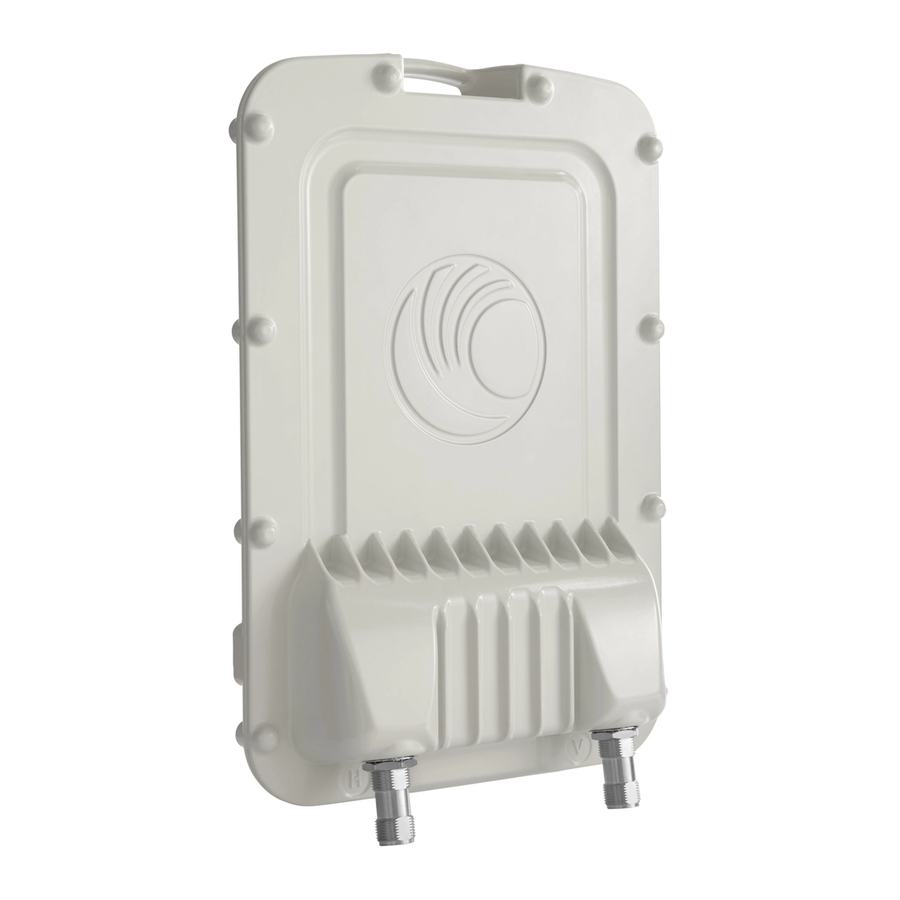
Chapter 2: System hardware Outdoor unit (ODU) The front of the connectorized ODU (Figure 11) provides N type female connectors for RF cable interfaces to antennas with horizontal (H) and vertical (V) polarization. Figure 11 Connectorized ODU antenna interfaces ODU specifications The PTP 650 ODU conforms to the specifications listed in Table Table 7 ODU specifications... -
Page 64: Power Supply Units (Psu)
Chapter 2: System hardware Power supply units (PSU) Power supply units (PSU) PSU description The PSU is an indoor unit that is connected to the ODU and network terminating equipment using Cat5e cable with RJ45 connectors. It is also plugged into an AC or DC power supply so that it can inject Power over Ethernet (POE) into the ODU. -
Page 65: Psu Part Numbers
Chapter 2: System hardware Power supply units (PSU) PSU part numbers Order PSUs and (for AC power) line cords from Cambium Networks (Table Table 8 Power supply component part numbers Cambium description Cambium part number PTP 650 AC Power Injector... -
Page 66: Ac+Dc Enhanced Power Injector Interfaces
Chapter 2: System hardware Power supply units (PSU) AC+DC Enhanced Power Injector interfaces The AC+DC Enhanced Power Injector interfaces are shown in Figure 14 and described in Table Figure 14 AC+DC Enhanced Power Injector interfaces Table 10 AC+DC Enhanced Power Injector interface functions Interface Function 100-240V 47-63Hz 1.5A... -
Page 67: Psu Specifications
Chapter 2: System hardware Power supply units (PSU) PSU specifications The PTP 650 AC Power Injector conforms to the specifications listed in Table The PTP 650 AC+DC Enhanced Power Injector conforms to the specifications listed in Table Table 11 AC Power Injector specifications Category Specification Dimensions... - Page 68 Chapter 2: System hardware Power supply units (PSU) Table 12 AC+DC Enhanced Power Injector specifications Category Specification Dimensions 250 mm (9.75 in) x 40 mm (1.5 in) x 80 mm (3 in) Weight 0.864 Kg (1.9 lbs) Temperature -40°C (-40°F) to +60°C (140°F) Humidity 0 to 90% non-condensing Waterproofing...
-
Page 69: Antennas And Antenna Cabling
ODU. Use weatherproof connectors, preferably ones that are supplied with adhesive lined heat shrink sleeves that are fitted over the interface between the cable and connector. Order RF cable and N type male connectors from Cambium Networks (Table 13). -
Page 70: Antenna Accessories
PTP 650 LPUs) are required for protecting the antenna RF cables at building entry. One arrestor is required per antenna cable. One example of a compatible lightning arrestor is the Polyphaser LSXL-ME or LSXL (not supplied by Cambium Networks). FCC and IC approved antennas... - Page 71 Chapter 2: System hardware Antennas and antenna cabling Table 14 Antennas permitted for deployment in USA/Canada – 5.4 GHz Nom gain Parabolic Manufacturer Antenna Type (dBi) dish RFS 2-foot Parabolic, SPF2-52AN 27.9 Gabriel 2-foot High Performance Dual QuickFire Gabriel 28.1 Parabolic, HQFD2-52-N RadioWaves Radio Waves 2-foot Dual-Pol Parabolic, SPD2-5.2...
- Page 72 Chapter 2: System hardware Antennas and antenna cabling Nom gain Parabolic Manufacturer Antenna Type (dBi) dish Andrew Andrew 3-foot Parabolic, P3F-52 33.4 RFS 4-foot HP Parabolic, SDF4-52AN 33.9 RFS 4-foot Parabolic, SPF4-52AN 33.9 Gabriel 4-foot High Performance Dual QuickFire Gabriel 34.3 Parabolic, HQFD4-52-N Gabriel 4-foot High Performance QuickFire Parabolic,...
- Page 73 Chapter 2: System hardware Antennas and antenna cabling Nom gain Parabolic Manufacturer Antenna Type (dBi) dish Andrew Andrew 1-foot Flat Panel Single, UBP300-4-1 Andrew Andrew 1.25-foot Flat Panel Dual, UBXP375-4-1 Table 15 Antennas permitted for deployment in USA/Canada – 5.8 GHz Nom Gain Parabolic Manufacturer...
- Page 74 Chapter 2: System hardware Antennas and antenna cabling Nom Gain Parabolic Manufacturer Antenna Type (dBi) Dish RadioWaves Radio Waves 3-foot Parabolic, SP3-2/5 31.4 RadioWaves Radio Waves 3-foot Parabolic, SP3-5.2 31.4 Cambium 5.25-5.85 GHZ, 3-FT (0.9M), SINGLE-POL, RDH4513B 31.4 Andrew Andrew 3-foot Dual-Pol Parabolic, PX3F-52 33.4 Andrew Andrew 3-foot Parabolic, P3F-52...
- Page 75 Chapter 2: System hardware Antennas and antenna cabling Nom Gain Parabolic Manufacturer Antenna Type (dBi) Dish Gabriel 6-foot High Performance QuickFire Parabolic, Gabriel 37.4 HQF6-52-N RFS 6-foot HP Parabolic, SDF6-52AN 37.4 RFS 6-foot Parabolic, SPF6-52AN 37.4 RadioWaves Radio Waves 6-foot Dual-Pol Parabolic, SPD6-5.2 37.5 Andrew Andrew 6-foot Dual-Pol Parabolic, PX6F-52...
-
Page 76: Ethernet Cabling
Chapter 2: System hardware Ethernet cabling Ethernet cabling Ethernet standards and cable lengths All configurations require a copper Ethernet connection from the ODU (PSU port) to the PSU. Advanced configurations may also require one or both of the following: • A copper Ethernet connection from the ODU (Aux port) to an auxiliary device. -
Page 77: Outdoor Copper Cat5E Ethernet Cable
15). Caution Always use Cat5e cable that is gel-filled and shielded with copper-plated steel. Alternative types of drop cable are not supported by Cambium Networks. Order Superior Essex type BBDGe cable from Cambium Networks (Table 18). Other lengths of this cable are available from Superior Essex. -
Page 78: Cable Grounding Kit
Optical cables do not require grounding. One grounding kit (Figure 16) is required for each grounding point on the PSU, Aux and copper SFP drop cables. Order cable grounding kits from Cambium Networks (Table 19). Caution... -
Page 79: Lightning Protection Unit (Lpu) And Grounding Kit
Chapter 2: System hardware Ethernet cabling Lightning protection unit (LPU) and grounding kit PTP 650 LPUs provide transient voltage surge suppression for PTP 650 installations. Each PSU or Aux drop cable requires two LPUs, one near the ODU and the other near the linked device, usually at the building entry point (Table 20). -
Page 80: Rj45 Connectors And Spare Glands
EMC glands must be used instead. EMC strain relief cable glands (quantity 5) are included in the LPU and grounding kit (Figure 17). These are identified with a black sealing nut. If extra glands are required, order them from Cambium Networks (in packs of 10) (Table 22). -
Page 81: Cable Hoisting Grip
Cable hoisting grip One or more grips are required for hoisting the drop cable up to the ODU without damaging the gland or RJ45 plug (Figure 18). They are not supplied by Cambium Networks. Figure 18 Cable hoisting grip Page 2-25... -
Page 82: Drop Cable Tester
The drop cable tester is an optional item for testing the resistances between the RJ45 pins of the drop cable (Figure 19). Order it by completing the order form on the support website (see Contacting Cambium Networks on page 1). Figure 19 Drop cable tester Indoor Cat5e cable To connect the PSU to network terminating equipment, use indoor Cat5e cable. -
Page 83: Sfp Module Kits
Chapter 2: System hardware Ethernet cabling SFP module kits SFP module kits allow connection of a PTP 650 Series ODU to a network over a Gigabit Ethernet interface in one of the following full-duplex modes: • Optical Gigabit Ethernet: 1000BaseLX or 1000BaseSX •... - Page 84 (Figure • Long EMC strain relief cable gland (Figure • The PTP 650 Series SFP Interface Upgrade Guide • License key instructions and unique Access Key Figure 20 Optical or copper SFP transceiver module Figure 21 Long cable gland Page...
-
Page 85: Optical Cable And Connectors
Chapter 2: System hardware Ethernet cabling Optical cable and connectors Order an optical cable with LC connectors from a specialist fabricator, quoting the specification shown in Figure 22. It must be the correct length to connect the ODU to the other device. LC connectors should be supplied with dust caps to prevent dust build up. -
Page 86: Chapter 3: System Planning
Chapter 3: System planning This chapter provides information to help the user to plan a PTP 650 link. The following topics are described in this chapter: • Typical deployment on page contains diagrams illustrating typical PTP 650 site deployments. • Site planning on page describes factors to be considered when planning the proposed link... -
Page 87: Typical Deployment
Chapter 3: System planning Typical deployment Typical deployment This section contains diagrams illustrating typical PTP 650 site deployments. ODU with POE interface to PSU In the basic configuration, there is only one Ethernet interface, a copper Cat5e power over Ethernet (POE) from the PSU to the ODU (PSU port), as shown in the following diagrams: mast or tower installation (Figure 23... - Page 88 Chapter 3: System planning Typical deployment Figure 24 Wall installation Page...
- Page 89 Chapter 3: System planning Typical deployment Figure 25 Roof installation Page...
-
Page 90: Sfp And Aux Ethernet Interfaces
Chapter 3: System planning Typical deployment SFP and Aux Ethernet interfaces There may be one or two additional Ethernet interfaces connected to the ODU: one to the SFP port (copper or optical) and one to the Aux port, as shown in the following diagrams: •... - Page 91 Chapter 3: System planning Typical deployment Figure 27 ODU with optical SFP and PSU interfaces Page...
- Page 92 Chapter 3: System planning Typical deployment Figure 28 ODU with Aux and PSU interfaces Page...
-
Page 93: Site Planning
Chapter 3: System planning Site planning Site planning This section describes factors to be considered when planning the proposed link end sites, including grounding, lightning protection and equipment location. Grounding and lightning protection Warning Electro-magnetic discharge (lightning) damage is not covered under warranty. The recommendations in this guide, when followed correctly, give the user the best protection from the harmful effects of EMD. - Page 94 Chapter 3: System planning Site planning Figure 29 Rolling sphere method to determine the lightning protection zones Assess locations on masts, towers and buildings to determine if the location is in Zone A or Zone • Zone A: In this zone a direct lightning strike is possible. Do not mount equipment in this zone. •...
-
Page 95: Site Grounding System
Chapter 3: System planning Site planning Site grounding system Confirm that the site has a correctly installed grounding system on a common ground ring with access points for grounding PTP 650 equipment. If the outdoor equipment is to be installed on the roof of a high building (Figure 25), confirm that the following additional requirements are met:... -
Page 96: Odu Wind Loading
Chapter 3: System planning Site planning ODU wind loading Ensure that the ODU and the structure on which it is mounted are capable of withstanding the prevalent wind speeds at a proposed PTP 650 site. Wind speed statistics should be available from national meteorological offices. -
Page 97: Psu Dc Power Supply
Chapter 3: System planning Site planning Note For a connectorized ODU, add the wind loading of the external antenna to that of the ODU. The antenna manufacturer should be able to quote wind loading. PSU DC power supply If using the DC input on the AC+DC power injector, ensure that the DC power supply meets the following requirements: •... -
Page 98: Drop Cable Grounding Points
Chapter 3: System planning Site planning Drop cable grounding points To estimate how many grounding kits are required for each drop cable, refer to the site installation diagrams (Figure 23 , Figure 24 Figure 25) and use the following criteria: •... -
Page 99: Multiple Lpus
Chapter 3: System planning Site planning Multiple LPUs If two or three drop cables are connected to the ODU, the PSU and Aux drop cables each require their own top LPU, and the copper SFP drop cable requires a top surge protector, not a PTP 650 (Figure 30). - Page 100 Chapter 3: System planning Site planning Figure 31 ODU with PSU, Aux and optical SFP interfaces Figure 32 Bottom LPU and surge protector Page 3-15...
-
Page 101: Radio Spectrum Planning
Chapter 3: System planning Radio spectrum planning Radio spectrum planning This section describes how to plan PTP 650 links to conform to the regulatory restrictions that apply in the country of operation. Caution It is the responsibility of the user to ensure that the PTP product is operated in accordance with local regulatory limits. -
Page 102: Regulatory Limits
8° Regulatory limits Many countries impose EIRP limits (Allowed EIRP) on products operating in the bands used by the PTP 650 Series. For example, in the 5.4 GHz and 5.8 GHz bands, these limits are calculated as follows: • In the 5.4 GHz band (5470 MHz to 5725 MHz), the EIRP must not exceed the lesser of 30 dBm or (17 + 10 x Log Channel width in MHz) dBm. -
Page 103: Available Spectrum
Chapter 3: System planning Radio spectrum planning Available spectrum The available spectrum for operation depends on the regulatory band. When configured with the appropriate license key, the unit will only allow operation on those channels which are permitted by the regulations. Note In Italy, there is a regulation which requires a general authorization of any 5.4 GHz radio link which is used outside the operator’s own premises. -
Page 104: Frequency Selection
Chapter 3: System planning Radio spectrum planning Frequency selection Regions without mandatory radar detection In regions that do not mandate DFS, choose DSO or Fixed Frequency: • Dynamic Spectrum Optimization (DSO): In this mode, the unit monitors the spectrum looking for the channel with the lowest level of interference. -
Page 105: Avoidance Of Weather Radars (Usa Only)
Chapter 3: System planning Radio spectrum planning Avoidance of weather radars (USA only) To comply with FCC rules (KDB 443999: Interim Plans to Approve UNII Devices Operating in the 5470 - 5725 MHz Band with Radar Detection and DFS Capabilities), units which are installed within 35 km (22 miles) of a Terminal Doppler Weather Radar (TDWR) system (or have a line of sight propagation path to such a system) must be configured to avoid any frequency within +30 MHz or –30 MHz of the frequency of the TDWR device. -
Page 106: Link Planning
The PTP 650 Series will operate at ranges from 100 m (330 ft) to 200 km (125 miles), within 3 modes: 0-40 km (0-25 miles), 0-100 km (0-62 miles) and 0-200 km (0-124 miles). Operation of the system will depend on obstacles in the path between the units. -
Page 107: Path Loss
Chapter 3: System planning Link planning LoS links in radar regions When planning an LoS link to operate in a radar detection region, ensure that receiver signal level is low enough to allow the PTP 650 to detect radar signals: •... -
Page 108: Calculating Data Rate Capacity
Chapter 3: System planning Link planning Calculating data rate capacity The data rate capacity of a PTP link is defined as the maximum end-to-end Ethernet throughput (including Ethernet headers) that it can support. It is assumed that Ethernet frames are 1500 octet. Data rate capacity is determined by the following factors: •... - Page 109 Chapter 3: System planning Link planning Calculation example Suppose that the link characteristics are: • PTP 650 variant = Mid • Link Symmetry = 1:1 • Link Mode Optimization = TDM • Modulation Mode = 64QAM 0.92 Dual • Channel Bandwidth = 10 MHz •...
-
Page 110: Planning For Connectorized Units
Chapter 3: System planning Planning for connectorized units Planning for connectorized units This section describes factors to be taken into account when planning to use connectorized ODUs with external antennas in PTP 650 links. When to install connectorized units The majority of radio links can be successfully deployed with the integrated ODU. However the integrated units may not be sufficient in some areas, for example: •... -
Page 111: Calculating Rf Cable Length (5.8 Ghz Fcc Only)
Chapter 3: System planning Planning for connectorized units Note Under Industry Canada regulations, this radio transmitter may only operate using an antenna of a type and maximum (or lesser) gain approved for the transmitter by Industry Canada. To reduce potential radio interference to other users, the antenna type and its gain should be so chosen that the equivalent isotropically radiated power (EIRP) is not more than that necessary for successful communication. -
Page 112: Data Network Planning
Chapter 3: System planning Data network planning Data network planning This section describes factors to be considered when planning PTP 650 data networks. Ethernet interfaces The PTP 650 Ethernet ports conform to the specifications listed in Table Table 32 PTP 650 Ethernet bridging specifications Ethernet Bridging Specification Protocol... -
Page 113: Ethernet Port Allocation
Chapter 3: System planning Data network planning Ethernet port allocation Decide how the three Ethernet ports will be allocated to the customer data network, in-band management and out-of-band local management, based on the following rules: • Ensure that one port is allocated to Data Only or Data and In-Band Management. This port should be associated with the customer data network. -
Page 114: Ip Interface
Chapter 3: System planning Data network planning IP interface Select the IP version for the IP interface of the ODU management agent. PTP 650 can operate in IPv4 mode, IPv6 mode, or in a dual IPv4/IPv6 mode. Choose one IPv4 address and/or one IPv6 address for the IP interface of the ODU management agent. -
Page 115: Daisy-Chaining" Ptp 650 Links
Chapter 3: System planning Data network planning An advantage of Ethernet priority is that any VLAN-tagged frame can be marked with a priority, regardless of the higher-layer protocols contained within the frame. A disadvantage of Ethernet priority is that the priority in the frame must be regenerated whenever traffic passes through a router. -
Page 116: Network Management Planning
RFC-3418. SNMPv2-MIB • RFC-3826. SNMP-USM-AES-MIB • RFC-4293 IP-MIB • PTP 650 Series proprietary MIB Note The proprietary MIBs are provided in the PTP 650 Series software download files in the support website (see Contacting Cambium Networks on page 1). Page 3-31... -
Page 117: Supported Diagnostic Alarms
Chapter 3: System planning Network management planning Supported diagnostic alarms PTP 650 supports the diagnostic alarms listed in Table 101. The web-based interface may be used to enable or disable generation of each supported SNMP notification or diagnostic alarm. Enabling SNMP Enable the SNMP interface for use by configuring the following attributes in the SNMP Configuration page: •... -
Page 118: Security Planning
Chapter 3: System planning Security planning Security planning This section describes how to plan for PTP 650 links to operate in secure mode. Planning for SNTP operation Note PTP 650 does not have a battery-powered clock, so the set time is lost each time the ODU is powered down. - Page 119 Chapter 3: System planning Security planning Item Description Quantity required TLS Private Key An RSA private key of size 2048 bytes, generated in Two pairs per link. These and Public either PKCS#1 or PKCS#5 format, unencrypted, and items are unique to IP Certificates encoded in the ASN.1 DER format.
-
Page 120: Planning For Snmpv3 Operation
Chapter 3: System planning Security planning Planning for SNMPv3 operation SNMP security mode Decide how SNMPv3 security will be configured. MIB-based security management uses standard SNMPv3 MIBs to configure the user-based security model and the view-based access control model. This approach provides considerable flexibility, allowing a network operator to tailor views and security levels appropriate for different types of user. - Page 121 Chapter 3: System planning Security planning Identify the security level for each of the security roles. Three security levels are available: (a) No authentication, no privacy; (b) Authentication, no privacy; (c) Authentication, privacy. If authentication is required, identify the protocol. Two authentication protocols are available: MD5 or SHA.
- Page 122 Chapter 3: System planning Security planning SNMPv3 default configuration (MIB-based) When SNMPv3 MIB-based Security Mode is enabled, the default configuration for the table is based on one initial user and four template users as listed in Table usmUserTable Table 36 Default SNMPv3 users Object Entry 1 Name...
- Page 123 Chapter 3: System planning Security planning VACM default configuration The default user is assigned to VACM group in the initial initial vacmSecurityToGroupTable table. The template users are not assigned to a group. PTP 650 creates default view trees and access as shown in Table 37 Table Table 37 Default VACM view trees...
-
Page 124: Planning For Radius Operation
Chapter 3: System planning Security planning Planning for RADIUS operation Configure RADIUS where remote authentication is required for users of the web-based interface. Remote authentication has the following advantages: • Control of passwords can be centralized. • Management of user accounts can be more sophisticated. For example; users can be prompted by a network manager to change passwords at regular intervals. - Page 125 Chapter 3: System planning Security planning If the vendor-specific auth-role attribute is absent, but the standard service-type (Type 6) attribute is present, PTP 650 selects the role for the authenticated user according to service-type. The supported values of service-type are as follows: •...
-
Page 126: System Threshold, Output Power And Link Loss
Chapter 3: System planning System threshold, output power and link loss System threshold, output power and link loss The following tables specify the system threshold (dBm), output power (dBm) and maximum link loss (dB) per channel bandwidth and modulation mode: •... - Page 127 Chapter 3: System planning System threshold, output power and link loss Table 41 4.9 GHz - TDM mode - threshold, power and link loss Modulation mode System threshold (dBm) Output power Maximum link loss (dB) per channel bandwidth (dBm) per channel bandwidth 10 MHz 20 MHz All bands...
- Page 128 Chapter 3: System planning System threshold, output power and link loss Table 42 5.4 GHz - IP mode - threshold, power and link loss Modulation mode System threshold (dBm) Output Maximum link loss (dB) per channel bandwidth power per channel bandwidth (dBm) bands BPSK 0.63 single...
- Page 129 Chapter 3: System planning System threshold, output power and link loss Table 43 5.4 GHz - TDM mode - threshold, power and link loss Modulation mode System threshold (dBm) Output Maximum link loss (dB) per channel bandwidth power per channel bandwidth (dBm) bands BPSK 0.63 single...
- Page 130 Chapter 3: System planning System threshold, output power and link loss Table 44 5.8 GHz - IP mode - threshold, power and link loss Modulation mode System threshold (dBm) Output Maximum link loss (dB) per channel bandwidth power per channel bandwidth (dBm) bands BPSK 0.63 single...
- Page 131 Chapter 3: System planning System threshold, output power and link loss Table 45 5.8 GHz - TDM mode - threshold, power and link loss Modulation mode System threshold (dBm) Output Maximum link loss (dB) per channel bandwidth power per channel bandwidth (dBm) bands BPSK 0.63 single...
-
Page 132: Data Throughput Capacity Tables
Chapter 3: System planning Data throughput capacity tables Data throughput capacity tables Use the following tables to look up the data throughput rates (Mbits/s) that are achieved when two PTP 650 ODUs are linked and the link distance (range) is 0 km: PTP 650 variant Link symmetry Link optimization... - Page 133 Chapter 3: System planning Data throughput capacity tables Table 46 Throughput at zero link range (Mbit/s), Full, symmetry 1:1, optimization IP Modulation mode 45 MHz (Tx/Rx/Aggregate) 40 MHz (Tx/Rx/Aggregate) 256QAM 0.81 dual 226.1 226.1 452.2 206.3 206.3 412.6 64QAM 0.92 dual 190.5 190.5 381.0...
- Page 134 Chapter 3: System planning Data throughput capacity tables Table 47 Throughput at zero link range (Mbit/s), Full, symmetry 1:1, optimization TDM Modulation mode 45 MHz (Tx/Rx/Aggregate) 40 MHz (Tx/Rx/Aggregate) 256QAM 0.81 dual 202.1 202.1 404.1 186.1 186.1 372.1 64QAM 0.92 dual 170.2 170.2 340.5...
- Page 135 Chapter 3: System planning Data throughput capacity tables Table 48 Throughput at zero link range (Mbit/s), Full, symmetry 2:1, optimization IP Modulation mode 45 MHz (Tx/Rx/Aggregate) 40 MHz (Tx/Rx/Aggregate) 256QAM 0.81 dual 299.7 149.9 449.6 273.6 136.8 410.5 64QAM 0.92 dual 252.5 126.3 378.8...
- Page 136 Chapter 3: System planning Data throughput capacity tables Table 49 Throughput at zero link range (Mbit/s), Full, symmetry 2:1, optimization TDM Modulation mode 45 MHz (Tx/Rx/Aggregate) 40 MHz (Tx/Rx/Aggregate) 256QAM 0.81 dual 280.8 140.4 421.2 257.7 128.9 386.6 64QAM 0.92 dual 236.6 118.3 354.8...
- Page 137 Chapter 3: System planning Data throughput capacity tables Table 50 Throughput at zero link range (Mbit/s), Full, symmetry adaptive, optimization IP Modulation mode 45 MHz (Tx/Rx/Aggregate) 40 MHz (Tx/Rx/Aggregate) 256QAM 0.81 dual 407.9 40.8 448.7 367.9 40.9 408.8 64QAM 0.92 dual 343.7 34.4 378.0...
- Page 138 Chapter 3: System planning Data throughput capacity tables Table 51 Throughput at zero link range (Mbit/s), Mid, symmetry 1:1, optimization IP Modulation mode 45 MHz (Tx/Rx/Aggregate) 40 MHz (Tx/Rx/Aggregate) 256QAM 0.81 dual 127.0 127.0 254.0 116.0 116.0 232.0 64QAM 0.92 dual 107.0 107.0 214.0...
- Page 139 Chapter 3: System planning Data throughput capacity tables Table 52 Throughput at zero link range (Mbit/s), Mid, symmetry 1:1, optimization TDM Modulation mode 45 MHz (Tx/Rx/Aggregate) 40 MHz (Tx/Rx/Aggregate) 256QAM 0.81 dual 113.0 113.0 226.0 104.0 104.0 208.0 64QAM 0.92 dual 95.0 95.0 190.0...
- Page 140 Chapter 3: System planning Data throughput capacity tables Table 53 Throughput at zero link range (Mbit/s), Mid, symmetry 2:1, optimization IP Modulation mode 45 MHz (Tx/Rx/Aggregate) 40 MHz (Tx/Rx/Aggregate) 256QAM 0.81 dual 168.0 84.0 252.0 153.0 77.0 230.0 64QAM 0.92 dual 141.0 71.0 212.0...
- Page 141 Chapter 3: System planning Data throughput capacity tables Table 54 Throughput at zero link range (Mbit/s), Mid, symmetry 2:1, optimization TDM Modulation mode 45 MHz (Tx/Rx/Aggregate) 40 MHz (Tx/Rx/Aggregate) 256QAM 0.81 dual 157.0 79.0 236.0 144.0 72.0 216.0 64QAM 0.92 dual 132.0 66.0 198.0...
- Page 142 Chapter 3: System planning Data throughput capacity tables Table 55 Throughput at zero link range (Mbit/s), Mid, symmetry adaptive, optimization IP Modulation mode 45 MHz (Tx/Rx/Aggregate) 40 MHz (Tx/Rx/Aggregate) 256QAM 0.81 dual 228.0 23.0 251.0 206.0 23.0 229.0 64QAM 0.92 dual 192.0 19.0 211.0...
- Page 143 Chapter 3: System planning Data throughput capacity tables Table 56 Throughput at zero link range (Mbit/s), Lite, symmetry 1:1, optimization IP Modulation mode 45 MHz (Tx/Rx/Aggregate) 40 MHz (Tx/Rx/Aggregate) 256QAM 0.81 dual 63.0 63.0 126.0 58.0 58.0 116.0 64QAM 0.92 dual 53.0 53.0 106.0...
- Page 144 Chapter 3: System planning Data throughput capacity tables Table 57 Throughput at zero link range (Mbit/s), Lite, symmetry 1:1, optimization TDM Modulation mode 45 MHz (Tx/Rx/Aggregate) 40 MHz (Tx/Rx/Aggregate) 256QAM 0.81 dual 57.0 57.0 114.0 52.0 52.0 104.0 64QAM 0.92 dual 48.0 48.0 96.0...
- Page 145 Chapter 3: System planning Data throughput capacity tables Table 58 Throughput at zero link range (Mbit/s), Lite, symmetry 2:1, optimization IP Modulation mode 45 MHz (Tx/Rx/Aggregate) 40 MHz (Tx/Rx/Aggregate) 256QAM 0.81 dual 84.0 42.0 126.0 77.0 38.0 115.0 64QAM 0.92 dual 71.0 35.0 106.0...
- Page 146 Chapter 3: System planning Data throughput capacity tables Table 59 Throughput at zero link range (Mbit/s), Lite, symmetry 2:1, optimization TDM Modulation mode 45 MHz (Tx/Rx/Aggregate) 40 MHz (Tx/Rx/Aggregate) 256QAM 0.81 dual 79.0 39.0 118.0 72.0 36.0 108.0 64QAM 0.92 dual 66.0 33.0 99.0...
- Page 147 Chapter 3: System planning Data throughput capacity tables Table 60 Throughput at zero link range (Mbit/s), Lite, symmetry adaptive, optimization IP Modulation mode 45 MHz (Tx/Rx/Aggregate) 40 MHz (Tx/Rx/Aggregate) 256QAM 0.81 dual 114.0 11.0 125.0 103.0 11.0 114.0 64QAM 0.92 dual 96.0 10.0 106.0...
- Page 148 Chapter 3: System planning Data throughput capacity tables Figure 33 Range adjustment for PTP 650, symmetry 1:1, optimization IP, bandwidth 45 MHz Figure 34 Range adjustment for PTP 650, symmetry 1:1, optimization IP, bandwidth 40 MHz Page 3-63...
- Page 149 Chapter 3: System planning Data throughput capacity tables Figure 35 Range adjustment for PTP 650, symmetry 1:1, optimization IP, bandwidth 20 MHz Figure 36 Range adjustment for PTP 650, symmetry 1:1, optimization IP, bandwidth 10 MHz Page 3-64...
- Page 150 Chapter 3: System planning Data throughput capacity tables Figure 37 Range adjustment for PTP 650, symmetry 1:1, optimization TDM, bandwidth 45 MHz Figure 38 Range adjustment for PTP 650, symmetry 1:1, optimization TDM, bandwidth 40 MHz Page 3-65...
- Page 151 Chapter 3: System planning Data throughput capacity tables Figure 39 Range adjustment for PTP 650, symmetry 1:1, optimization TDM, bandwidth 20 MHz Figure 40 Range adjustment for PTP 650, symmetry 1:1, optimization TDM, bandwidth 10 MHz Page 3-66...
- Page 152 Chapter 3: System planning Data throughput capacity tables Figure 41 Range adjustment for PTP 650, symmetry 2:1, optimization IP, bandwidth 45 MHz Figure 42 Range adjustment for PTP 650, symmetry 2:1, optimization IP, bandwidth 40 MHz Page 3-67...
- Page 153 Chapter 3: System planning Data throughput capacity tables Figure 43 Range adjustment for PTP 650, symmetry 2:1, optimization IP, bandwidth 20 MHz Page 3-68...
- Page 154 Chapter 3: System planning Data throughput capacity tables Figure 44 Range adjustment for PTP 650, symmetry 2:1, optimization IP, bandwidth 10 MHz Page 3-69...
- Page 155 Chapter 3: System planning Data throughput capacity tables Figure 45 Range adjustment for PTP 650, symmetry 2:1, optimization TDM, bandwidth 45 MHz Page 3-70...
- Page 156 Chapter 3: System planning Data throughput capacity tables Figure 46 Range adjustment for PTP 650, symmetry 2:1, optimization TDM, bandwidth 40 MHz Figure 47 Range adjustment for PTP 650, symmetry 2:1, optimization TDM, bandwidth 20 MHz Page 3-71...
- Page 157 Chapter 3: System planning Data throughput capacity tables Figure 48 Range adjustment for PTP 650, symmetry 2:1, optimization TDM, bandwidth 10 MHz Page 3-72...
- Page 158 Chapter 3: System planning Data throughput capacity tables Figure 49 Range adjustment for PTP 650, adaptive, optimization IP, bandwidth 45 MHz Page 3-73...
- Page 159 Chapter 3: System planning Data throughput capacity tables Figure 50 Range adjustment for PTP 650, adaptive, optimization IP, bandwidth 40 MHz Page 3-74...
- Page 160 Chapter 3: System planning Data throughput capacity tables Figure 51 Range adjustment for PTP 650, adaptive, optimization IP, bandwidth 20 MHz Page 3-75...
- Page 161 Chapter 3: System planning Data throughput capacity tables Figure 52 Range adjustment for PTP 650, adaptive, optimization IP, bandwidth 10 MHz Page 3-76...
-
Page 162: Chapter 4: Legal And Regulatory Information
The following topics are described in this chapter: • Cambium Networks end user license agreement on page contains the Cambium and third party license agreements for the PTP 650 Series products. • Compliance with safety standards on page 4-23 lists the safety specifications against which the PTP 650 has been tested and certified. -
Page 163: Cambium Networks End User License Agreement
Acceptance of this agreement In connection with Cambium Networks’ delivery of certain proprietary software or products containing embedded or pre-loaded proprietary software, or both, Cambium Networks is willing to license this certain proprietary software and the accompanying documentation to you only on the condition that you accept all the terms in this End User License Agreement (“Agreement”). -
Page 164: Conditions Of Use
1 copy, which then may not be copied. With regard to the copy made for backup or archival purposes, you agree to reproduce any Cambium Networks copyright notice, and other proprietary legends appearing thereon. Such copyright notice(s) may appear in any of several forms, including machine-readable form, and you agree to reproduce such notice in each form in which it appears, to the extent it is physically possible to do so. -
Page 165: Title And Restrictions
Title and copyrights to the Software and Documentation and any copies made by you remain with Cambium Networks and its licensors. You will not, and will not permit others to: (i) modify, translate, decompile, bootleg, reverse engineer, disassemble, or extract the inner workings of the Software or Documentation, (ii) copy the look-and-feel or functionality of the Software or Documentation;... -
Page 166: Right To Use Cambium's Name
Except as required in “Conditions of use”, you will not, during the term of this Agreement or thereafter, use any trademark of Cambium Networks, or any word or symbol likely to be confused with any Cambium Networks trademark, either alone or in any combination with another word or words. -
Page 167: Disclaimer
Limitation of liability IN NO EVENT SHALL CAMBIUM NETWORKS BE LIABLE TO YOU OR ANY OTHER PARTY FOR ANY DIRECT, INDIRECT, GENERAL, SPECIAL, INCIDENTAL, CONSEQUENTIAL, EXEMPLARY OR OTHER DAMAGE ARISING OUT OF THE USE OR INABILITY TO USE THE PRODUCT (INCLUDING,... -
Page 168: Term Of License
Software will terminate immediately without notice upon a breach of this Agreement by you. Within 30 days after termination of this Agreement, you will certify to Cambium Networks in writing that through your best efforts, and to the best of your knowledge, the original and all... - Page 169 Chapter 4: Legal and regulatory information Cambium Networks end user license agreement Trademarks Java Technology and/or J2ME : Java and all other Java-based marks are trademarks or registered trademarks of Sun Microsystems, Inc. in the U.S. and other countries. UNIX : UNIX is a registered trademark of The Open Group in the United States and other countries.
- Page 170 Chapter 4: Legal and regulatory information Cambium Networks end user license agreement • Redistributions in binary form must reproduce the above copyright notice, this list of conditions and the following disclaimer in the documentation and/or other materials provided with the distribution.
- Page 171 Chapter 4: Legal and regulatory information Cambium Networks end user license agreement California 95054, U.S.A. All rights reserved. Use is subject to license terms below. This distribution may include materials developed by third parties. Sun, Sun Microsystems, the Sun logo and Solaris are trademarks or registered trademarks of Sun Microsystems, Inc.
- Page 172 Chapter 4: Legal and regulatory information Cambium Networks end user license agreement THIS SOFTWARE IS PROVIDED BY THE COPYRIGHT HOLDERS AND CONTRIBUTORS “AS IS” AND ANY EXPRESS OR IMPLIED WARRANTIES, INCLUDING, BUT NOT LIMITED TO, THE IMPLIED WARRANTIES OF MERCHANTABILITY AND FITNESS FOR A PARTICULAR PURPOSE ARE DISCLAIMED.
- Page 173 Chapter 4: Legal and regulatory information Cambium Networks end user license agreement • Redistributions of source code must retain the above copyright notice, this list of conditions and the following disclaimer. • Redistributions in binary form must reproduce the above copyright notice, this list of conditions and the following disclaimer in the documentation and/or other materials provided with the distribution.
- Page 174 Chapter 4: Legal and regulatory information Cambium Networks end user license agreement THIS SOFTWARE IS PROVIDED BY THE OpenSSL PROJECT “AS IS” AND ANY EXPRESSED OR IMPLIED WARRANTIES, INCLUDING, BUT NOT LIMITED TO, THE IMPLIED WARRANTIES OF MERCHANTABILITY AND FITNESS FOR A PARTICULAR PURPOSE ARE DISCLAIMED. IN NO...
- Page 175 Chapter 4: Legal and regulatory information Cambium Networks end user license agreement The word ‘cryptographic’ can be left out if the routines from the library being used are not cryptographic related. 4. If you include any Windows specific code (or a derivative thereof) from the apps directory (application code) you must include an acknowledgement: “This product includes software written by Tim Hudson (tjh@cryptsoft.com)”...
- Page 176 Chapter 4: Legal and regulatory information Cambium Networks end user license agreement Libpng libpng versions 1.2.6, August 15, 2004, through 1.2.35, February 14, 2009, are Copyright © 2004, 2006-2008 Glenn Randers-Pehrson, and are distributed according to the same disclaimer and license as libpng-1.2.5 with the following individual added to the list of Contributing Authors...
- Page 177 Chapter 4: Legal and regulatory information Cambium Networks end user license agreement Andreas Dilger Dave Martindale Guy Eric Schalnat Paul Schmidt Tim Wegner The PNG Reference Library is supplied “AS IS”. The Contributing Authors and Group 42, Inc. disclaim all warranties, expressed or implied, including, without limitation, the warranties of merchantability and of fitness for any purpose.
- Page 178 Chapter 4: Legal and regulatory information Cambium Networks end user license agreement 1. Redistributions of source code must retain the above copyright notice, this list of conditions and the following disclaimer. 2. The origin of this software must not be misrepresented; you must not claim that you wrote the original software.
- Page 179 Chapter 4: Legal and regulatory information Cambium Networks end user license agreement Apache Apache License Version 2.0, January 2004 http://www.apache.org/licenses/ TERMS AND CONDITIONS FOR USE, REPRODUCTION, AND DISTRIBUTION 1. Definitions. "License" shall mean the terms and conditions for use, reproduction, and distribution as defined by Sections 1 through 9 of this document.
- Page 180 Chapter 4: Legal and regulatory information Cambium Networks end user license agreement the copyright owner. For the purposes of this definition, "submitted" means any form of electronic, verbal, or written communication sent to the Licensor or its representatives, including but not limited to...
- Page 181 Chapter 4: Legal and regulatory information Cambium Networks end user license agreement pertain to any part of the Derivative Works, in at least one of the following places: within a NOTICE text file distributed as part of the Derivative Works; within the Source form or documentation, if provided along with the Derivative Works;...
- Page 182 Chapter 4: Legal and regulatory information Cambium Networks end user license agreement and charge a fee for, acceptance of support, warranty, indemnity, or other liability obligations and/or rights consistent with this License. However, in accepting such obligations, You may act only...
- Page 183 Chapter 4: Legal and regulatory information Cambium Networks end user license agreement D3 JS library Copyright (c) 2013, Michael Bostock All rights reserved. Redistribution and use in source and binary forms, with or without modification, are permitted provided that the following conditions are met: * Redistributions of source code must retain the above copyright notice, this list of conditions and the following disclaimer.
-
Page 184: Compliance With Safety Standards
Chapter 4: Legal and regulatory information Compliance with safety standards Compliance with safety standards This section lists the safety specifications against which the PTP 650 has been tested and certified. It also describes how to keep RF exposure within safe limits. Electrical safety compliance The PTP 650 hardware has been tested for compliance to the electrical safety specifications listed Table... -
Page 185: Human Exposure To Radio Frequency Energy
Chapter 4: Legal and regulatory information Compliance with safety standards Human exposure to radio frequency energy Relevant standards (USA and EC) applicable when working with RF equipment are: • ANSI IEEE C95.1-1991, IEEE Standard for Safety Levels with Respect to Human Exposure to Radio Frequency Electromagnetic Fields, 3 kHz to 300 GHz. - Page 186 Chapter 4: Legal and regulatory information Compliance with safety standards Calculation of power density The following calculation is based on the ANSI IEEE C95.1-1991 method, as that provides a worst case analysis. Details of the assessment to EN50383:2002 can be provided, if required. Peak power density in the far field of a radio frequency point source is calculated as follows: π...
- Page 187 Chapter 4: Legal and regulatory information Compliance with safety standards Table 63 Power compliance margins Band Antenna Tx burst (W/m 4.9 GHz Integrated 0.25 Connectorized 0.25 6.25 5.4 GHz Integrated 0.005 0.004 0.08 12.5 External 4ft Dish 0.00035 0.00028 2884 0.08 5.8 GHz Integrated...
-
Page 188: Compliance With Radio Regulations
Caution Changes or modifications not expressly approved by Cambium Networks could void the user’s authority to operate the system. Caution For the connectorized version of the product and in order to reduce potential radio... - Page 189 Chapter 4: Legal and regulatory information Compliance with radio regulations Table 65 Radio certifications (5.4 GHz) Region Regulatory approvals FCC 47 CFR Part 15 E Canada IC RSS-210 Issue 8, Annex 9 (or latest) Europe ETSI EN301 893 v1.6.1 Table 66 Radio certifications (5.8 GHz) Region Regulatory approvals FCC 47 CFR Part 15 C...
-
Page 190: Fcc/Ic Compliance
Chapter 4: Legal and regulatory information Compliance with radio regulations FCC/IC compliance The PTP 650 complies with the regulations that are in force in the USA and Canada. Caution If this equipment does cause interference to radio or television reception, refer to Radio and television interference on page 8-10... - Page 191 Chapter 4: Legal and regulatory information Compliance with radio regulations 5.4 GHz FCC and IC notification This device complies with part 15.407 of the US FCC Rules and Regulations and with Industry Canada RSS-210 Annex 9. Operation is subject to the following two conditions: (1) This device may not cause harmful interference, and (2) This device must accept any interference received, including interference that may cause undesired operation.
-
Page 192: European Union Compliance
Chapter 4: Legal and regulatory information Compliance with radio regulations European Union compliance The PTP 650 complies with the regulations that are in force in the European Union. Caution This is a Class A product. In a domestic environment this product may cause radio interference, in which case the user may be required to take adequate measures. - Page 193 The operator is responsible for obtaining any national licenses required to operate this product and these must be obtained before using the product in any particular country. Hereby, Cambium Networks declares that the PTP 650 product complies with the essential requirements and other relevant provisions of Directive 1999/5/EC. The declaration of conformity...
- Page 194 Chapter 5: Installation This chapter describes how to install and test the hardware for a PTP 650 link. It contains the following topics: • Safety on page contains important safety guidelines that must be observed by personnel installing or operating PTP 650 equipment. •...
-
Page 195: Chapter 5: Installation
Exercise extreme care when working at heights. Always use one of the Cambium PTP 650 Series power supply units (PSU) to power the ODU. Failure to use a Cambium supplied PSU could result in equipment damage and will invalidate the safety certification and may cause a safety hazard. -
Page 196: Dc Supply
For outdoor copper Cat5e Ethernet interfaces, always use Cat5e cable that is gel-filled and shielded with copper-plated steel. Alternative types of drop cable are not supported by Cambium Networks. Drop cable tester The PSU output voltage may be hazardous in some conditions, for example in wet weather. Do NOT connect the drop cable tester to the PSU, either directly or via LPUs. -
Page 197: Minimum Separation Distances
Chapter 5: Installation Safety Minimum separation distances Ensure that personnel are not exposed to unsafe levels of RF energy. The units start to radiate RF energy as soon as they are powered up. Never work in front of the antenna when the ODU is powered. -
Page 198: Installing The Odu And Top Lpu
Chapter 5: Installation Installing the ODU and top LPU Installing the ODU and top LPU Decide how to mount the ODU and top LPU Page... -
Page 199: Prepare Odu For Mounting
Chapter 5: Installation Installing the ODU and top LPU Note For improved radio performance, mount the integrated ODU at 45 degrees to the vertical. The mounting pole may be vertical or horizontal. Prepare ODU for mounting 1 Use the correct mounting bracket for the pole diameter and ODU type: •... -
Page 200: Integrated Odu
Chapter 5: Installation Installing the ODU and top LPU 2 (a) Fasten one ground cable to each ODU grounding point using the M6 (small) lugs: one is for the top LPU (M6 lug at other end) and the other is for the tower or building (M10 lug at other end). - Page 201 Chapter 5: Installation Installing the ODU and top LPU 3 (a) For back-to-back LPU mounting, fix the ODU to the pole using the LPU. (b) For separate LPU mounting, fix the ODU to the pole using the bracket strap. (a) Back-to-back LPU: (b) Separate LPU: Caution Do not reverse the ODU bracket strap,...
-
Page 202: Connectorized Odu
Chapter 5: Installation Installing the ODU and top LPU Connectorized ODU 1 (a) Line up the bolt heads with receptacles in the ODU. (b) Fix the mounting plate and bracket bolts to the back of the ODU using the bolts and washers. Tighten to a torque setting of 5 Nm (4 lb ft). -
Page 203: Ground The Odu And Top Lpu
Chapter 5: Installation Installing the ODU and top LPU Ground the ODU and top LPU Caution Do not attach grounding cables to the ODU mounting bracket bolts, as this arrangement will not provide full protection. 1 For separate LPU mounting, use the U-bolt bracket from the LPU kit to mount the top LPU on the pole below the ODU. -
Page 204: Install External Antennas For A Connectorized Odu
Chapter 5: Installation Installing the ODU and top LPU Install external antennas for a connectorized ODU 1 Mount the antenna(s) according to manufacturer’s instructions. When using separate antennas to achieve spatial diversity, mount one with Horizontal polarization and the other with Vertical polarization. - Page 205 Chapter 5: Installation Installing the ODU and top LPU 7 Ground the antenna cables to the supporting structure within 0.3 meters (1 foot) of the ODU and antennas using the Cambium grounding kit (part number 01010419001): 8 Fix the antenna cables to the supporting structure using site approved methods. Ensure that no undue strain is placed on the ODU or antenna connectors.
-
Page 206: Installing The Copper Cat5E Ethernet Interface
Caution Always use Cat5e cable that is gel-filled and shielded with copper-plated steel. Alternative types of Cat5e cable are not supported by Cambium Networks. Cambium Networks supply this cable (Cambium part numbers WB3175 and WB3176), RJ45 connectors (Cambium part number WB3177) and a crimp tool (Cambium part number WB3211). - Page 207 Chapter 5: Installation Installing the copper Cat5e Ethernet interface Fit the parts into the body and lightly screw on the gland nut (do not tighten it): Connect the drop cable to the ODU (PSU port) and LPU (a) Plug the RJ45 connector into the socket in the unit, ensuring that it snaps home. (b) Fit the gland body to the RJ45 port and tighten it to a torque of 5.5 Nm (4.3 lb ft): (a) Fit the gland nut and tighten until the rubber seal closes on the cable.
-
Page 208: Install The Main Drop Cable
Chapter 5: Installation Installing the copper Cat5e Ethernet interface Disconnect the drop cable from the LPU or ODU Use this procedure if it is necessary to remove an EMC strain relief cable gland and RJ45 connector from the ODU (as illustrated) or LPU. 1 (a) Remove the gland nut. - Page 209 Chapter 5: Installation Installing the copper Cat5e Ethernet interface Warning Failure to obey the following precautions may result in injury or death: • Use the proper hoisting grip for the cable being installed. If the wrong hoisting grip is used, slippage or insufficient gripping strength will result. •...
- Page 210 Chapter 5: Installation Installing the copper Cat5e Ethernet interface Fit the RJ45 connector housing as shown. To ensure there is effective strain relief, locate the cable inner sheath under the connector housing tang. Do not tighten the gland nut: Hoist and fix the main drop cable Warning Failure to obey the following precautions may result in injury or death: •...
-
Page 211: Install The Bottom Lpu To Psu Drop Cable
Chapter 5: Installation Installing the copper Cat5e Ethernet interface Attach the main drop cable to the supporting structure using site approved methods. Ground the main drop cable At all required grounding points, connect the screen of the main drop cable to the metal of the supporting structure using the cable grounding kit (Cambium part number 01010419001). - Page 212 Chapter 5: Installation Installing the copper Cat5e Ethernet interface Fasten one ground cable to the bottom LPU using the M6 (small) lug. Tighten both nuts to a torque of 5 Nm (3.9 lb ft): Locking nut Washer M6 lug Washer Toothed washer M10 lug to ground Select a building grounding point near the LPU bracket.
-
Page 213: Test Resistance In The Drop Cable
Chapter 5: Installation Installing the copper Cat5e Ethernet interface At the PSU end only: Do not fit a cable gland. Strip the cable outer sheath and fit the RJ45 connector load bar. Fit the RJ45 connector housing. To ensure there is effective strain relief, locate the cable inner sheath under the connector housing tang: Test resistance in the drop cable Connect the bottom end of the copper Cat5e drop cable to a PTP drop cable tester and test that the... -
Page 214: Installing The Psu
Chapter 5: Installation Installing the PSU Installing the PSU Install one of the following types of PSU (as specified in the installation plan): • PTP 650 AC Power Injector (Cambium part number N000065L001). • PTP 650 AC+DC Enhanced Power Injector (Cambium part number C000065L002). Caution As the PSU is not waterproof, locate it away from sources of moisture, either in the equipment building or in a ventilated moisture-proof enclosure. -
Page 215: Installing The Ac+Dc Enhanced Power Injector
Chapter 5: Installation Installing the PSU Installing the AC+DC Enhanced Power Injector Follow this procedure to install the AC+DC Enhanced Power Injector (Cambium part number C000065L002): Mount the AC+DC power injector by screwing it to a vertical or horizontal surface using the four screw holes (circled): Form a drip loop on the PSU end of the LPU to PSU drop cable. -
Page 216: Installing An Sfp Ethernet Interface
Chapter 5: Installation Installing an SFP Ethernet interface Installing an SFP Ethernet interface In more advanced configurations, there may be an optical or copper Cat5e Ethernet interface connected to the SFP port of the ODU. Refer to Typical deployment on page for diagrams of these configurations. - Page 217 Chapter 5: Installation Installing an SFP Ethernet interface Figure 57 ODU with copper Cat5e connections to all three Ethernet ports Page 5-24...
-
Page 218: Fitting The Long Cable Gland
Chapter 5: Installation Installing an SFP Ethernet interface Fitting the long cable gland Optical SFP interface: Disassemble the long cable gland and thread its components over the LC connector at the ODU end as shown below. Copper Cat5e SFP interface: Disassemble the long cable gland and thread its components over the RJ45 connector at the ODU end as shown below. -
Page 219: Inserting The Sfp Module
Chapter 5: Installation Installing an SFP Ethernet interface Fit the parts into the body and lightly screw on the gland nut (do not tighten it): Optical Copper Inserting the SFP module To insert the SFP module into the ODU, proceed as follows: Remove the blanking plug from the SFP port of the ODU: Page 5-26... - Page 220 Chapter 5: Installation Installing an SFP Ethernet interface Insert the SFP module into the SFP receptacle with the label up: Optical Copper Push the module home until it clicks into place: Optical Copper Page 5-27...
- Page 221 Chapter 5: Installation Installing an SFP Ethernet interface Rotate the latch to the locked position: Optical Copper Page 5-28...
-
Page 222: Connecting The Cable
Chapter 5: Installation Installing an SFP Ethernet interface Connecting the cable Caution The fiber optic cable assembly is very delicate. To avoid damage, handle it with extreme care. Ensure that the fiber optic cable does not twist during assembly, especially when fitting and tightening the weatherproofing gland. Do not insert the power over Ethernet drop cable from the PSU into the SFP module, as this will damage the module. -
Page 223: Fitting The Gland
Chapter 5: Installation Installing an SFP Ethernet interface Fitting the gland Fit the gland body to the SFP port and tighten it to a torque of 5.5 Nm (4.3 lb ft) Fit the gland nut and tighten until the rubber seal closes on the cable. Do not over-tighten the gland nut, as there is a risk of damage to its internal components: Correct Incorrect... -
Page 224: Removing The Cable And Sfp Module
Chapter 5: Installation Installing an SFP Ethernet interface Removing the cable and SFP module Do not attempt to remove the module without disconnecting the cable, otherwise the locking mechanism in the ODU will be damaged. Remove the cable connector by pressing its release tab before pulling it out: Optical Copper Rotate the latch to the unlocked position. -
Page 225: Installing An Aux Ethernet Interface
Chapter 5: Installation Installing an Aux Ethernet interface Installing an Aux Ethernet interface In more advanced configurations, there may be a copper Cat5e Ethernet interface connected to the Aux port of the ODU. Refer to Typical deployment on page for a diagram of this configuration. Adapt the installation procedures in this chapter as appropriate for the Aux interface, noting the following differences: •... -
Page 226: Supplemental Installation Information
Chapter 5: Installation Supplemental installation information Supplemental installation information This section contains detailed installation procedures that are not included in the above topics, such as how to strip cables, create grounding points and weatherproof connectors. Stripping drop cable When preparing drop cable for connection to the PTP 650 ODU or LPU, use the following measurements: When preparing drop cable for connection to the PTP 650 PSU (without a cable gland), use the following measurements:... -
Page 227: Creating A Drop Cable Grounding Point
Chapter 5: Installation Supplemental installation information Creating a drop cable grounding point Use this procedure to connect the screen of the main drop cable to the metal of the supporting structure using the cable grounding kit (Cambium part number 01010419001). To identify suitable grounding points, refer to Drop cable grounding points on page 3-13. - Page 228 Chapter 5: Installation Supplemental installation information Tighten the cable ties with pliers. Cut the surplus from the cable ties. Cut a 38mm (1.5 inches) section of self-amalgamating tape and wrap it completely around the joint between the drop and ground cables. Use the remainder of the self-amalgamating tape to wrap the complete assembly.
- Page 229 Chapter 5: Installation Supplemental installation information Wrap a layer of PVC tape from bottom to top, starting from 25 mm (1 inch) below and finishing 25 mm (1 inch) above the edge of the self-amalgamating tape, over lapping at half width.
-
Page 230: Weatherproofing An N Type Connector
Chapter 5: Installation Supplemental installation information 10 Clamp the bottom lug of the grounding cable to the supporting structure using site approved methods. Use a two-hole lug secured with fasteners in both holes. This provides better protection than a single-hole lug. Weatherproofing an N type connector Use this procedure to weatherproof the N type connectors fitted to the connectorized ODU and external antenna (if recommended by the antenna manufacturer). - Page 231 Chapter 5: Installation Supplemental installation information Cut a 125mm (5 inches) length of rubber tape (self-amalgamating): Expand the width of the tape by stretching it so that it will wrap completely around the connector and cable: Press the tape edges together so that there are no gaps. The tape should extend 25 mm (1 inch) beyond the PVC tape: Wrap a layer of 50 mm (2 inch) PVC tape from bottom to top, starting from 25 mm (1 inch) below the edge of the self-amalgamating tape, overlapping at half width.
- Page 232 Chapter 5: Installation Supplemental installation information Repeat with a further four layers of 19 mm (0.75 inch) PVC tape, always overlapping at half width. Wrap the layers in alternate directions: • Second layer: top to bottom. • Third layer: bottom to top. •...
-
Page 233: Replacing Psu Fuses
Chapter 5: Installation Supplemental installation information Replacing PSU fuses The AC+ DC Enhanced Power Injector contains two replaceable fuses. These fuses protect the positive and negative grounded DC input voltages. If an incorrect power supply (that is, not in the range 37V to 60V DC) is connected to the DC input terminals, one or both fuses may blow. -
Page 234: Chapter 6: Configuration And Alignment
Chapter 6: Configuration and alignment This chapter describes how to use the web interface to configure the PTP 650 link. It also describes how to align antennas. This chapter contains the following topics: • Preparing for configuration and alignment on page •... -
Page 235: Preparing For Configuration And Alignment
Chapter 6: Configuration and alignment Preparing for configuration and alignment Preparing for configuration and alignment This section describes the checks to be performed before proceeding with unit configuration and antenna alignment. Safety precautions All national and local safety standards must be followed while configuring the units and aligning the antennas. -
Page 236: Generating A License Key
C000065K023 (*1) If the Cambium description contains the words “per ODU”, then order two upgrades per link. (*2) Cambium Networks will supply these upgrades only if there is official permission to export AES encryption to the country of operation. Page... - Page 237 Go to the Cambium Support web page (see Contacting Cambium Networks on page 1) and navigate to the Cambium Networks License Key Generator. • Complete the required fields, including MAC Address and Country. For SFP capability, AES encryption and data throughput upgrades only, enter the Access Key.
-
Page 238: Connecting To The Unit
Chapter 6: Configuration and alignment Connecting to the unit Connecting to the unit This section describes how to connect the unit to a management PC and power it up. Configuring the management PC Use this procedure to configure the local management PC to communicate with the PTP 650. Procedure: Select Properties for the Ethernet port. -
Page 239: Connecting To The Pc And Powering Up
Chapter 6: Configuration and alignment Connecting to the unit Enter an IP address that is valid for the 169.254.X.X network, avoiding 169.254.0.0 and 169.254.1.1. A good example is 169.254.1.3: Enter a subnet mask of 255.255.0.0. Leave the default gateway blank. Connecting to the PC and powering up Use this procedure to connect a management PC and power up the PTP 650. -
Page 240: Using The Web Interface
Chapter 6: Configuration and alignment Using the web interface Using the web interface This section describes how to log into the PTP 650 web interface and use its menus. Logging into the web interface Use this procedure to log into the web interface as a system administrator. Procedure: Start the web browser from the management PC. -
Page 241: Using The Menu Options
Chapter 6: Configuration and alignment Using the web interface Using the menu options Use the menu navigation bar in the left panel to navigate to each web page. Some of the menu options are only displayed for specific system configurations. Use Table 68 to locate information about using each web page. - Page 242 Chapter 6: Configuration and alignment Using the web interface Main menu Menu option Web page information Installation Installation menu on page 6-10 Graphical Install Graphical Install page on page 6-92 Management Web-Based Management page on page 6-39 Local User Accounts Local User Accounts page on page 6-42...
-
Page 243: Installation Menu
Chapter 6: Configuration and alignment Installation menu Installation menu This section describes how to use the Installation Wizard to complete the essential system configuration tasks that must be performed on a new link. Caution If the system designer has provided a list of channels to be barred for TDWR radar avoidance, the affected channels must be barred before the units are allowed to radiate on site, otherwise the regulations will be infringed. -
Page 244: Disarm Installation Page
Chapter 6: Configuration and alignment Installation menu Disarm Installation page Menu option: Installation (Figure 58). This page is displayed only when unit is armed. Figure 58 Disarm Installation page (top and bottom of page shown) To disarm the unit, click Disarm Installation Agent. Current Installation Summary page Menu option: Installation (Figure... -
Page 245: Software License Key Page
Chapter 6: Configuration and alignment Installation menu Software License Key page Menu option: Installation (Figure 60). Use this page to configure the unit with a new License Key and to review the capabilities of an installed License Key. The Capability Summary section is not displayed until a License Key is submitted and accepted. - Page 246 Chapter 6: Configuration and alignment Installation menu Note Full capability is available only when both ODUs have the trial active or are already licensed to operate with that capacity. When the trial has started, the Software License Key page displays the Trial Period Remaining attribute (Figure 61).
-
Page 247: Interface Configuration Page
Chapter 6: Configuration and alignment Installation menu Interface Configuration page Menu option: Installation (Figure 63). Use this page to update the IP interface attributes. Figure 63 Interface Configuration page (showing Dual IPv4 and IPv6) Review and update the attributes: they are repeated in the LAN Configuration page (Table 71). -
Page 248: Wireless Configuration Page
Chapter 6: Configuration and alignment Installation menu Wireless Configuration page Menu option: Installation (Figure 64). This page is part of the Installation Wizard. Use it to update the wireless attributes. Figure 64 Wireless Configuration page Procedure: • Update the attributes (Table 69). - Page 249 Chapter 6: Configuration and alignment Installation menu Caution The lower center frequency attribute must be configured to the same value for both the Master and Slave, otherwise the wireless link will fail to establish. The only way to recover from this situation is to modify the Lower Center Frequency attributes so that they are identical on both the master and slave units.
- Page 250 Chapter 6: Configuration and alignment Installation menu Attribute Meaning Max Receive The maximum mode the unit will use as its adaptive modulation. By Modulation Mode default the Max Receive Modulation Mode is the highest mode available. For minimum error rates, set the maximum modulation mode to the minimum necessary to carry the required traffic.
- Page 251 When this type of network is designed, the Color Code values are normally specified in the link planning report. In all other cases, Cambium Networks recommend that Tx Color Code and Rx Color Code are left at the default value of A.
- Page 252 Chapter 6: Configuration and alignment Installation menu Attribute Meaning Installation Mode Arm With Tones: Audio tones will be emitted during antenna alignment (the recommended option). Arm Without Tones: Audio tones will not be emitted during antenna alignment. Change Config Without Arming: Configuration changes will be made without arming the ODU for alignment.
-
Page 253: Confirm Installation Configuration Page
Chapter 6: Configuration and alignment Installation menu Confirm Installation Configuration page Menu option: Installation (Figure 65). Use this page to review and confirm the updated wireless configuration of the unit. Figure 65 Confirm Installation Configuration page (top and bottom of page shown) Procedure: •... -
Page 254: System Menu
Chapter 6: Configuration and alignment System menu System menu This section describes how to configure the IP and Ethernet interfaces of the PTP 650 unit. System Configuration page Menu option: System > Configuration (Figure 66). Use this page to enable AES encryption and to review and update key wireless attributes of the unit. - Page 255 Chapter 6: Configuration and alignment System menu Procedure: • If AES encryption is required but the System Configuration page does not contain the Encryption Algorithm or Encryption Key attributes, then order the necessary AES capability upgrade, generate a license key and enter it on the Software License Key page (Software License Key page on page 6-12).
- Page 256 Chapter 6: Configuration and alignment System menu Attribute Meaning Lowest Ethernet The lowest modulation mode that must be achieved before the link is Modulation Mode allowed to bridge Ethernet frames. Ethernet Capped Disabled: Wireless speed is not limited by the connected Ethernet link. Max Wireless Speed Enabled: Wireless speed is limited to a mode that the connected Ethernet link can sustain.
-
Page 257: Lan Configuration Page
Chapter 6: Configuration and alignment System menu LAN Configuration page Menu option: System > Configuration > LAN Configuration (Figure 67). Use this page to control how users connect to the PTP 650 web interface, either from a locally connected computer or from a management network. - Page 258 Chapter 6: Configuration and alignment System menu Caution Before configuring a VLAN for management interfaces, ensure that the VLAN is accessible, otherwise the unit will be inaccessible after the next reboot. Caution Before configuring in-band management, ensure that the Master and Slave units are configured with different IP addresses, otherwise the management agent will not be able to distinguish the two units.
- Page 259 Chapter 6: Configuration and alignment System menu Table 71 IP interface attributes Attribute Meaning IP Version The internet protocols to be supported by this ODU: IPv4: IPv4 protocols only. IPv4 attributes are displayed. IPv6: IPv6 protocols only. IPv6 attributes are displayed. Dual IPv4 and IPv6: Both IPv4 and IPv6 protocols.
- Page 260 Chapter 6: Configuration and alignment System menu Attribute Meaning VLAN Management Only displayed when Use VLAN for Management Interfaces is not set to No VLAN Tagging. The VLAN VID (range 0 to 4094) that will be included in Ethernet frames generated by the management interfaces. VLAN Management Only displayed when Use VLAN for Management Interfaces is not set Priority...
- Page 261 Chapter 6: Configuration and alignment System menu Table 72 Main PSU Port and Aux Port attributes Attribute Meaning Auto Negotiation Disabled: Configuration of the Ethernet interface is forced. Enabled: Configuration of the Ethernet interface is automatically negotiated (default). This is the preferred setting. See the caution at the start of this section about auto-negotiation versus forced Ethernet configuration.
- Page 262 Chapter 6: Configuration and alignment System menu Table 73 Bridging attributes Attribute Meaning Local Packet Enabled: The management agent learns the location of end stations Filtering from the source addresses in received management frames. The agent filters transmitted management frames to ensure that the frame is transmitted at the Ethernet (data or management) port, or over the wireless link as appropriate.
-
Page 263: Qos Configuration Page
Chapter 6: Configuration and alignment System menu QoS Configuration page Menu option: System > Configuration > QoS Configuration (Figure 68 Figure 69). Use this page to control the quality of service configuration. Classification may be based on fields in the Ethernet header (Layer 2) or in the network header (Layer 3). The unit recognizes two network layer protocols: IP and MPLS. - Page 264 Chapter 6: Configuration and alignment System menu Figure 69 QoS Configuration page (IP/MPLS) Page 6-31...
- Page 265 Chapter 6: Configuration and alignment System menu Procedures: • Review and update the attributes: Layer 2 and Priority Scheme (Table 74). • To use IEEE 802.1Q classification rules, click Reset Default Priority Mappings. • To save changes, click: Submit Updated Configuration. Note Priority mapping must be configured the same at both Master and Slave units on the wireless link.
-
Page 266: Sfp Configuration Page
Chapter 6: Configuration and alignment System menu SFP Configuration page Menu option: System > Configuration > SFP Configuration. This page is only available when the ODU detects an optical (Figure 70) or copper (Figure 71) SFP module in the SFP port. Use it to configure the way in which the unit connects to the network via the SFP interface. -
Page 267: Save & Restore Configuration Page
Chapter 6: Configuration and alignment System menu Procedure (only applies when copper SFP module is installed): • Update the attributes (Table 75). • To save changes, click Submit Updated System Configuration. Table 75 SFP Configuration (copper SFP module) attributes Attribute Meaning SFP Port Auto Disabled: Configuration of the Ethernet interface is forced. - Page 268 Chapter 6: Configuration and alignment System menu Figure 72 Save & Restore Configuration page Save the system configuration in the following situations: • After a new unit has been fully configured as described in this chapter. • After any change has been made to the configuration. •...
- Page 269 Chapter 6: Configuration and alignment System menu Most of the configuration can be restored from the backup. However, certain attributes that were part of the configuration are not saved or restored automatically. Use the web interface to reconfigure the following attributes: •...
-
Page 270: Software Upgrade Page
Go to the Cambium Support web page (see Contacting Cambium Networks on page 1) and navigate to Point-to-Point Software and Documentation, PTP 650 Series. • If the support web page contains a later Software Version than that installed on the PTP 650 unit, perform the procedure below. - Page 271 Chapter 6: Configuration and alignment System menu Procedure: Save the system configuration; see Save & Restore Configuration page on page 6-34. On the Cambium Support web page, select the latest PTP 650 software image (dld2 file) and save it to the local management PC. On the Software Upgrade page, click Browse.
-
Page 272: Management Menu
Chapter 6: Configuration and alignment Management menu Management menu This section describes how to configure web-based management of the PTP 650 unit. Web-Based Management page Menu option: Management > Web (Figure 74). Use this page to configure web-based management of the unit. Figure 74 Web-Based Management page Page 6-39... - Page 273 Chapter 6: Configuration and alignment Management menu Caution If the HTTP, HTTPS, Telnet and SNMP interfaces are all disabled, then it will be necessary to use the Recovery image to reset IP & Ethernet Configuration back to defaults to re-enable the interfaces. Note The HTTP and Telnet interfaces should be disabled if the HTTPS interface is configured.
- Page 274 Chapter 6: Configuration and alignment Management menu Attribute Meaning SNMP Control of Disabled: Neither HTTP nor Telnet can be controlled remotely via SNMP. HTTP And Telnet Enabled: Both HTTP and Telnet can be controlled remotely via SNMP. SNMP Control of Enabled: Passwords for identity-based user accounts in the web-based Passwords interface can be updated via SNMP.
-
Page 275: Local User Accounts Page
Chapter 6: Configuration and alignment Management menu Local User Accounts page Menu option: Management > Web > Local User Accounts. The contents of this page depend upon the setting of Identity Based User Accounts: Disabled (Figure 75) or Enabled (Figure 76). - Page 276 Chapter 6: Configuration and alignment Management menu Figure 76 Local User Accounts page (Identity Based User Accounts enabled) Page 6-43...
- Page 277 Chapter 6: Configuration and alignment Management menu Procedure: • Choose whether to set Identity Based User Accounts to Disabled or Enabled. • Review and update the Local User Account Management attributes (Table 77). • If Identity Based User Accounts is set to Enabled: Review and update the Password Complexity Configuration attributes (Table 78).
- Page 278 Chapter 6: Configuration and alignment Management menu Attribute Meaning Password Expiry Only displayed when Identity Based User Accounts is Enabled. Action The action to be taken by the PTP 650 when a password expires. Table 78 Password Complexity Configuration attributes Attribute Meaning Best...
- Page 279 Chapter 6: Configuration and alignment Management menu Attribute Meaning Best practice Match Reversed No: Reversed patterns are not checked. Patterns Yes: Reversed patterns are checked. For example, if Maximum Repeated Pattern Length is set to 3 and Match Reversed Patterns is set to Yes, then AB1221BA will be rejected.
-
Page 280: Radius Configuration Page
Chapter 6: Configuration and alignment Management menu RADIUS Configuration page Menu option: Management > Web > Radius Configuration (Figure 77). Use this page to configure RADIUS authentication. RADIUS authentication is only available when PTP 650 is configured for Identity-based User Accounts and when RADIUS servers are connected to the network. - Page 281 Chapter 6: Configuration and alignment Management menu Note At least one user with Security Officer privileges must exist and be enabled, in order to disable the RADIUS client. Procedure: • Update the attributes (Table 80). • Click Submit RADIUS Configuration. Table 80 RADIUS Authentication attributes Attribute Meaning...
-
Page 282: Webpage Properties Page
Chapter 6: Configuration and alignment Management menu Attribute Meaning RADIUS Server Shared secret confirmation. Shared Secret Confirm Webpage Properties page Menu option: Management > Web > Web Properties (Figure 78). Use this page to control the display of the web interface. Figure 78 Webpage Properties page Procedure: •... - Page 283 Chapter 6: Configuration and alignment Management menu Table 81 Webpage Properties attributes Attribute Meaning Web Properties View Summary and Status pages without login: • If ticked (the default setting), users can view the Summary and Status web pages without entering a password. •...
- Page 284 Chapter 6: Configuration and alignment Management menu Table 82 Browser Title attribute variables Variable Meaning $siteName Site Name, as set in the System Configuration page (Table 70). $linkName Link Name, as set in the System Configuration page (Table 70). $masterSlaveMode Master Slave Mode, as set in the Step 2: Wireless Configuration page (Table...
-
Page 285: Email Configuration Page
Chapter 6: Configuration and alignment Management menu Email Configuration page Menu option: Management > Email (Figure 79). Use this page to enable the PTP 650 to generate Simple Mail Transfer Protocol (SMTP) email messages to notify the system administrator when certain events occur. - Page 286 SMTP server. By convention the default value for the port number is 25. SMTP Source Email The email address used by the PTP 650 Series to log into the SMTP Address server. This must be a valid email address that will be accepted by your SMTP Server.
-
Page 287: Diagnostic Alarms Page
Chapter 6: Configuration and alignment Management menu Diagnostic Alarms page Menu option: Management > Diagnostic Alarms (Figure 80). Use this page to select which diagnostic alarms will be notified to the system administrator. Figure 80 Diagnostic Alarms page Page 6-54... -
Page 288: Time Configuration Page
Chapter 6: Configuration and alignment Management menu Procedure: • Tick the required alarms. These alarms are described in Alarms on page 7-12. • Click Submit Updated Configuration. Time Configuration page Menu option: Management > Time (Figure 81 Figure Use this page to set the real-time clock of the PTP 650. Figure 81 Time Configuration page (SNTP disabled) Page 6-55... - Page 289 Chapter 6: Configuration and alignment Management menu Figure 82 Time Configuration page (SNTP enabled) Page 6-56...
- Page 290 Chapter 6: Configuration and alignment Management menu Setting the real-time clock manually Use this procedure to keep time without connecting to a networked time server. Note If SNTP is disabled, it will be necessary to reset the time manually after each system reboot.
- Page 291 Chapter 6: Configuration and alignment Management menu Table 85 SNTP clock attributes Attribute Meaning SNTP State Enabled: the ODU will obtain accurate date and time updates from a networked time server. SNTP Primary Server Specifies the primary SNTP server, determining the order in which the servers are tried.
-
Page 292: Syslog Configuration Page
Chapter 6: Configuration and alignment Management menu Attribute Meaning System Clock This displays the local time, allowing for the Time Zone and Daylight Saving settings. Local Time Settings: Time Zone Set the time zone offset from Greenwich Mean Time (GMT). To set the clock to UTC time, set Time Zone to GMT 00.00. - Page 293 Chapter 6: Configuration and alignment Management menu Note To record Coordinated Universal Time (UTC time) in syslog messages, use the Time Configuration page to set Time Zone to GMT 00.00 and Daylight Saving to Disabled (Time Configuration page on page 6-55). Procedure: •...
-
Page 294: Snmp Pages (For Snmpv3)
Chapter 6: Configuration and alignment SNMP pages (for SNMPv3) SNMP pages (for SNMPv3) This section describes how to configure Simple Network Management Protocol version 3 (SNMPv3) traps using the SNMP Wizard. Current SNMP Summary (for SNMPv3) Menu option: Management > SNMP (Figure 84). -
Page 295: Step 1: Snmp Configuration (For Snmpv3)
Chapter 6: Configuration and alignment SNMP pages (for SNMPv3) Step 1: SNMP Configuration (for SNMPv3) Menu option: Management > SNMP. Part of the SNMP Wizard (Figure 85). Use this page to enable SNMP, select SNMPv3 and configure access to the SNMP server. Figure 85 Step 1: SNMP Configuration page (for SNMPv3) Procedure: •... - Page 296 Chapter 6: Configuration and alignment SNMP pages (for SNMPv3) Table 87 Step 1: SNMP Configuration attributes (for SNMPv3) Attribute Meaning SNMP Minimum Minimum security level which is permitted to administer SNMP security Privilege Level settings. Only displayed when Identity Based User Accounts are Enabled on the User Accounts page (Table 77).
-
Page 297: Step 2: Snmp Mib-Ii System Objects (For Snmpv3)
Chapter 6: Configuration and alignment SNMP pages (for SNMPv3) Step 2: SNMP MIB-II System Objects (for SNMPv3) Menu option: Management > SNMP. Part of the SNMP Wizard (Figure 86). Use this page to enter details of the SNMP managed node. Figure 86 Step 2: SNMP MIB-II System Objects page (for SNMPv3) Procedure: •... -
Page 298: Step 3: Snmp User Policy Configuration (For Snmpv3)
Chapter 6: Configuration and alignment SNMP pages (for SNMPv3) Step 3: SNMP User Policy Configuration (for SNMPv3) Menu option: Management > SNMP. Part of the SNMP Wizard (Figure 87). This page is only displayed when SNMP Security Mode is set to Web-based in the Step 1: SNMP Configuration page. - Page 299 Chapter 6: Configuration and alignment SNMP pages (for SNMPv3) Attribute Meaning Authentication The authentication protocol to be used to access the PTP 650 via SNMP. Protocol This is disabled when Security Level is set to Auth No Priv. MD5: Message Digest Algorithm is used. SHA: NIST FIPS 180-1, Secure Hash Algorithm SHA-1 is used.
-
Page 300: Step 4: Snmp User Accounts Configuration (For Snmpv3)
Chapter 6: Configuration and alignment SNMP pages (for SNMPv3) Step 4: SNMP User Accounts Configuration (for SNMPv3) Menu option: Management > SNMP. Part of the SNMP Wizard (Figure 88). This page is only displayed when SNMP Security Mode is set to Web-based in the Step 1: SNMP Configuration page. - Page 301 Chapter 6: Configuration and alignment SNMP pages (for SNMPv3) Attribute Meaning Passphrase The phrase to be entered by this SNMP user to access the system using an authentication or privacy protocol. Length must be between 8 and 32 characters. May contain spaces. The Auth Passphrase is hidden when Security Level for this user’s Role is set to No Auth No Priv.
-
Page 302: Step 5: Snmp Trap Configuration (For Snmpv3)
Chapter 6: Configuration and alignment SNMP pages (for SNMPv3) Step 5: SNMP Trap Configuration (for SNMPv3) Menu option: Management > SNMP. Part of the SNMP Wizard (Figure 89). This page is only displayed when SNMP Security Mode is set to Web-based in the Step 1: SNMP Configuration page. -
Page 303: Confirm Snmp Configuration (For Snmpv3)
Chapter 6: Configuration and alignment SNMP pages (for SNMPv3) Table 91 Step 5: SNMP Trap Configuration attributes (for SNMPv3) Attribute Meaning SNMP Enabled Traps Select the events that will generate SNMP traps. SNMP Trap Receiver 1 and SNMP Trap Receiver 2: SNMP Trap Receiver Disabled: SNMP traps are not sent to the corresponding SNMP Enabled... -
Page 304: Snmp Pages (For Snmpv1/2C)
Chapter 6: Configuration and alignment SNMP pages (for SNMPv1/2c) SNMP pages (for SNMPv1/2c) This section describes how to configure Simple Network Management Protocol version 1 or 2c (SNMPv1 or SNMPv2c) traps using the SNMP Wizard. Current SNMP Summary (for SNMPv1/2c) Menu option: Management >... -
Page 305: Step 2: Snmp Mib-Ii System Objects (For Snmpv1/2C)
Chapter 6: Configuration and alignment SNMP pages (for SNMPv1/2c) Procedure: • Set SNMP State to Enabled. • Set SNMP Version to v1/2c. The page is redisplayed with SNMPv1/2c attributes. • Update the attributes (Table 92). • Click Next. Table 92 Step 1: SNMP Configuration attributes (for SNMPv1/2c) Attribute Meaning SNMP Minimum... -
Page 306: Step 3: Snmp Trap Configuration (For Snmpv1/2C)
Chapter 6: Configuration and alignment SNMP pages (for SNMPv1/2c) Step 3: SNMP Trap Configuration (for SNMPv1/2c) Menu option: Management > SNMP. Part of the SNMP Wizard (Figure 92). Figure 92 Step 3: SNMP Trap Configuration page (for SNMPv1/2c) Procedure: • Update the attributes (Table 93). -
Page 307: Confirm Snmp Configuration (For Snmpv1/2C)
Chapter 6: Configuration and alignment SNMP pages (for SNMPv1/2c) Table 93 Step 3: SNMP Trap Configuration attributes (for SNMPv1/2c) Attribute Meaning SNMP Trap Version Select the SNMP protocol version to use for SNMP traps: v1 or v2c. SNMP Enabled Select the events that will generate SNMP traps. Traps SNMP Trap Disabled: SNMP traps are not sent to the corresponding SNMP Trap... -
Page 308: Security Menu
Chapter 6: Configuration and alignment Security menu Security menu This section describes how to configure HTTPS/TLS security using the Security Wizard. Caution Ensure that the operator’s security requirements are configured before connecting the PTP 650 to the network. Otherwise, security may be compromised. Preparing for HTTPS/TLS Before running the Security Configuration Wizard, obtain the necessary cryptographic material and ensure that the unit has AES capability. -
Page 309: Security Configuration Wizard Page
Chapter 6: Configuration and alignment Security menu Security Configuration Wizard page Menu option: Security. Displayed only when AES encryption is enabled by license key (Figure 94). Use this page to review the current security configuration of the unit. Figure 94 Security Configuration Wizard page Procedure: •... -
Page 310: Step 1: Enter Key Of Keys
Chapter 6: Configuration and alignment Security menu Step 1: Enter Key of Keys Menu option: Security. Part of the Security Wizard (Figure 95). Use this page to enter a Key of Keys to encrypt all critical security parameters (CSPs) before they are stored in non-volatile memory. -
Page 311: Step 2: Enter Tls Private Key And Public Certificate
Chapter 6: Configuration and alignment Security menu Step 2: Enter TLS Private Key and Public Certificate Menu option: Security. Part of the Security Wizard (Figure 96). Use this page to select and upload the TLS Private Key and Public Certificate files. Figure 96 Step 2: Enter TLS Private Key and Public Certificate page Caution If the certificates expire, the unit will be unreachable. -
Page 312: Step 3: Enter User Security Banner
Chapter 6: Configuration and alignment Security menu Step 3: Enter User Security Banner Menu option: Security. Part of the Security Wizard (Figure 97). Use this page to enter a banner that will be displayed every time a user attempts to login to the wireless unit. -
Page 313: Step 4: Enter Login Information Settings
Chapter 6: Configuration and alignment Security menu Step 4: Enter Login Information Settings Menu option: Security. Part of the Security Wizard (Figure 98). Use this page to choose whether or not to display information about previous login attempts when the user logs into the web interface. Figure 98 Step 4: Enter Login Information Settings page Procedure: •... -
Page 314: Step 5: Enter Random Number Entropy Input
Chapter 6: Configuration and alignment Security menu Step 5: Enter Random Number Entropy Input Menu option: Security. Part of the Security Wizard (Figure 99). Use this page to enter entropy input to seed the internal random number algorithm. Figure 99 Step 5: Random Number Entropy Input page Procedure: •... -
Page 315: Step 6: Enter Wireless Link Encryption Key
Chapter 6: Configuration and alignment Security menu Step 6: Enter Wireless Link Encryption Key Menu option: Security. Part of the Security Wizard (Figure 100). Use this page to enable AES encryption and enter the encryption key. The wireless link encryption key is used to encrypt all traffic over the PTP 650 wireless link. -
Page 316: Step 7: Enter Http And Telnet Settings
Chapter 6: Configuration and alignment Security menu Step 7: Enter HTTP and Telnet Settings Menu option: Security. Part of the Security Wizard (Figure 101). Use this page to configure network management of the PTP 650 using one or more of the following methods: HTTPS, HTTP, Telnet or SNMP. - Page 317 Chapter 6: Configuration and alignment Security menu Note If HTTP, Telnet and SNMP are all disabled, the secure web server becomes the only management tool for the ODU web interface. To reenter the web interface after Step 7 of the Security Wizard, use the URL https://aa.bb.cc.dd (where aa.bb.cc.dd is the IP address of the unit).
-
Page 318: Step 8: Commit Security Configuration
Chapter 6: Configuration and alignment Security menu Step 8: Commit Security Configuration Menu option: Security. Part of the Security Wizard (Figure 102). Use this page to review and confirm the updated security configuration of the unit. Figure 102 Step 8: Commit Security Configuration page Page 6-85... -
Page 319: Zeroize Csps Page
Chapter 6: Configuration and alignment Security menu Procedure: • Review all changes that have been made in the Security Wizard. • To ensure that the changes take effect, click Commit Security Configuration and Reboot. The unit reboots and the changes take effect. Note If the Key of keys is entered or modified in the Security Wizard, user accounts are reset when Commit Security Configuration and Reboot is clicked. -
Page 320: Aligning Antennas
Chapter 6: Configuration and alignment Aligning antennas Aligning antennas This section describes how to align the antennas in a PTP 650 link, use the web interface to assist with alignment, and check wireless performance after alignment. Before performing this task, check that hardware installation is complete (apart from the network connections) at both the Master and Slave sites. -
Page 321: Aligning Antennas
Chapter 6: Configuration and alignment Aligning antennas Aligning antennas Use this procedure to align linked antennas (master and slave), whether integrated or connectorized. The goal of antenna alignment is to find the center of the main beam. This is done by adjusting the antennas while monitoring the receive signal level. -
Page 322: Aligning Separate Antennas For Spatial Diversity
Chapter 6: Configuration and alignment Aligning antennas When the antennas have been aligned on the center of the beam, verify that the receive level is within the predicted range (from the installation report). If this is not the case, go back to step 2. -
Page 323: Odu Installation Tones
Chapter 6: Configuration and alignment Aligning antennas ODU installation tones This is the first of two methods that may be used to monitor receive signal level during antenna alignment. The ODU emits audible tones during installation to assist with alignment. The pitch of the alignment tone is proportional to the received power of the wireless signals. - Page 324 • Ranging: The PTP 650 Series does not require the user to enter the link range. The Master unit typically takes less than 60 seconds to determine the length of the link being installed. The Master unit will remain in the Scanning state until the range of the link has been established.
-
Page 325: Graphical Install Page
Chapter 6: Configuration and alignment Aligning antennas Graphical Install page Menu option: Installation > Graphical Install (Figure 104). This is the second of two methods that may be used to monitor receive signal level during antenna alignment. Figure 104 Graphical Install page Procedure: •... -
Page 326: Disarming The Units
Chapter 6: Configuration and alignment Aligning antennas Disarming the units When antenna alignment is complete, use this procedure to disarm both units in the link in order • Turn off the audible alignment aid. • Enable adaptive modulation. • Fully enable spectrum management features (such as DSO, if configured). •... -
Page 327: Comparing Actual To Predicted Performance
Chapter 6: Configuration and alignment Aligning antennas Comparing actual to predicted performance For at least one hour of operation after disarming, use this procedure to monitor the link to check that it is achieving predicted levels of performance. PTP LINKPlanner provides the prediction in the form of an installation report. -
Page 328: Other Configuration Tasks
Chapter 6: Configuration and alignment Other configuration tasks Other configuration tasks This section describes other configuration tasks. Connecting to the network Use this procedure to complete and test network connections. Procedure: If a management PC is connected directly to the PTP 650, disconnect it. Confirm that all ODU Ethernet interface cables (PSU, SFP and Aux) are connected to the correct network terminating equipment or devices. -
Page 329: Upgrading Software Using Tftp
Chapter 6: Configuration and alignment Other configuration tasks Upgrading software using TFTP Use this procedure to upgrade software remotely using Trivial FTP (TFTP) triggered by SNMP. Procedure: Check that the TFTP client is enabled. Refer to Web-Based Management page on page 6-39. Set tFTP attributes as described in Table Monitor tFTP attributes as described in... - Page 330 Chapter 6: Configuration and alignment Other configuration tasks Table 97 Monitoring tFTP attributes Attribute Meaning tFTPSoftwareUpgradeStatus This is the current status of the TFTP software upgrade process. Values: idle(0) uploadinprogress(1) uploadsuccessfulprogrammingFLASH(2) upgradesuccessfulreboottorunthenewsoftwareimag e(3) upgradefailed(4). For example, enter this command: snmpget_d.exe -v 2c -c public 10.10.10.10 .iso.3.6.1.4.1.17713.7.9.9.0 tFTPSoftwareUpgradeStatus This describes the status of the TFTP software upgrade...
-
Page 331: Chapter 7: Operation
Chapter 7: Operation This chapter provides instructions for operators of the PTP 650 wireless Ethernet bridge. The following topics are described in this chapter: • System summary and status on page • Rebooting and logging out on page • Alarms, alerts and messages on page 7-12 •... -
Page 332: System Summary And Status
Chapter 7: Operation System summary and status System summary and status This section describes how to use the summary and status pages to monitor the status of the Ethernet ports and wireless link. System Summary page Menu option: Home (Figure 107). -
Page 333: System Status Page
Figure 108 System Status page The two PTP 650 Series units are arranged in a master and slave relationship. The roles of the units in this relationship are displayed in the page title. The master unit will always have the title “... - Page 334 Chapter 7: Operation System summary and status Note Link Symmetry is configured at the master ODU only. The appropriate matching Link Symmetry is set at the slave ODU automatically. For example, if Link Symmetry is configured as 2 to 1 at the master ODU, then the slave ODU will be set automatically as 1 to 2.
- Page 335 Chapter 7: Operation System summary and status Attribute Meaning Aux Port Status This indicates the current status of the Ethernet link to the Aux port. A state of “ ” with a green background indicates that an Copper Link Up Ethernet link is established.
- Page 336 = Received signal power at the local unit (dBm) = Antenna gain at the remote and local units respectively (dBi). The antenna gain of the PTP 650 Series (23.5 dBi) is used unless one or both of the units is a Connectorized version.
- Page 337 Table 100. Range The range between the PTP 650 Series ODUs. This is displayed in kilometers by default, but can be changed to miles by updating the Distance Units attribute to imperial, as described in Webpage Properties page on page 6-49.
- Page 338 Chapter 7: Operation System summary and status Value Meaning Limited By The Wireless The radio is running at the maximum achievable modulation Conditions mode given the current wireless conditions shown by the vector error. The radio is capable of reaching a higher modulation mode if wireless conditions (vector error) improve.
-
Page 339: Rebooting And Logging Out
Chapter 7: Operation Rebooting and logging out Rebooting and logging out This section describes how to reboot the unit and log out of the web interface. Login Information page Menu option: Management > Web > Login Information (Figure 109). Use this page to show recent successful and unsuccessful login attempts on this account. Figure 109 Login Information page Reboot Wireless Unit page Menu option: System >... -
Page 340: Change Password Page
Chapter 7: Operation Rebooting and logging out Procedure: • Use the drop-down list to view the Previous Reasons For Reset/Reboot. • If a reboot is required: Click Reboot Wireless Unit. The Reboot Confirmation dialog is displayed (Figure 111). Click OK. The reboot progress message is displayed. On completion, the unit restarts. Figure 111 Reboot confirmation pop up Change Password page Menu option: Change Password... -
Page 341: Logging Out
Chapter 7: Operation Rebooting and logging out Logging out To maintain security, always log out at the end of a session: on the menu, click Logout. The unit will log out automatically if there is no user activity for a set time, but this depends upon Auto Logout Period in the Webpage Properties page (Figure 78). -
Page 342: Alarms, Alerts And Messages
Chapter 7: Operation Alarms, alerts and messages Alarms, alerts and messages This section describes how to use alarms, alerts and syslog messages to monitor the status of a PTP 650 link. Alarms Whenever system alarms are outstanding, a yellow warning triangle is displayed on the navigation bar. - Page 343 Chapter 7: Operation Alarms, alerts and messages Table 101 System alarms Alarm Meaning Regulatory Band The installed license key contains an invalid Regulatory Band. The wireless unit is prohibited from operating outside the regulated limits. Install Status Signaling was received with the wrong MAC address. It is very unusual to detect this, because units with wrongly configured Target MAC Address will normally fail to establish a wireless link.
- Page 344 Chapter 7: Operation Alarms, alerts and messages Alarm Meaning Wireless Link Disabled Warning The wireless link has been administratively disabled via the SNMP Interface. The wireless interface MIB-II ifAdminStatus attribute has been set to DOWN. To enable the Ethernet interface, set the ifAdminStatus attribute to Main PSU Port Disabled Warning The PSU port link has been administratively disabled via the SNMP Interface.
-
Page 345: Email Alerts
Chapter 7: Operation Alarms, alerts and messages Alarm Meaning Syslog Local Wrapped The local log of event messages is full and is now being overwritten by new messages. Aux Port Configuration Mismatch Ethernet fragments (runt packets) have been detected when the Aux port is in full duplex. This indicates an auto- negotiation or forced configuration mismatch. -
Page 346: Syslog Page
Chapter 7: Operation Alarms, alerts and messages Syslog page Menu option: Management > Syslog (Figure 114). Use this page to view the local log of event messages. Figure 114 Syslog local log Note For more information about system logging, refer to: •... -
Page 347: Format Of Syslog Server Messages
Chapter 7: Operation Alarms, alerts and messages Format of syslog server messages PTP 650 generates syslog messages in this format: SP = “ ” = %x20 CO = “:” = %x3A SC = “;” = %x3B LT = “<” = %x3C GT = “>”... -
Page 348: Event Messages
Chapter 7: Operation Alarms, alerts and messages Event messages Event messages are listed in Table 103. Definition of abbreviations: SC = ";" SP = " " This is an example of an event message: PTP650: event; auth_login; web user=MarkT; from=169.254.1.1; port=80; connection=HTTP;... - Page 349 Chapter 7: Operation Alarms, alerts and messages Facility Severity Identifier Message content security(4) warning(4) snmpv3_auth "Authentication failure" SC local6(22) warning(4) snmpv3_decryption "Decryption failure" SC local6(22) warning(4) snmpv3_engine_id "Unknown engine ID" SC local6(22) warning(4) snmpv3_sec_level "Unknown security level" SC kernel(0) warning(4) sys_reboot "System Reboot, reason="...
- Page 350 Chapter 7: Operation Spectrum management Spectrum management This section describes how to use the spectrum management pages to monitor the radio spectrum usage of the PTP 650 link. Spectrum Management page Menu option: System > Spectrum Management (Figure 115 Figure 116).
- Page 351 Chapter 7: Operation Spectrum management Figure 116 Spectrum Management page (slave unit) All spectrum management configuration changes are applied at the master ODU only. These changes are then sent from the master to the slave, so that both master and slave keep identical copies of spectrum management configuration.
-
Page 352: Spectrum Management
Chapter 7: Operation Spectrum management Note Before attempting to improve the performance of the spectrum management algorithm by changing the default configuration, consult the Cambium Point-to-Point distributor or one of the system field support engineers. Procedure: • Review the configuration attributes (Table 104) •... -
Page 353: Spectrum Management Page
DSO will instruct the wireless to immediately move to a better channel. If a better channel cannot be found the PTP 650 Series will continue to use the current active channel. (Default –85 dBm). Channel Bandwidth This shows the value of the variable channel bandwidth selected. - Page 354 Chapter 7: Operation Spectrum management X axis and Y axis The X-axis shows a stylized view of the selectable wireless channels. Adjacent channels on the display have a 10 MHz overlap. Channels are displayed separately for clarity. The axis is labeled using the channel center frequencies in MHz.
- Page 355 Chapter 7: Operation Spectrum management Key metrics The “I” bar and top of the colored bar represent three key metrics (Table 106). The vertical part of the “I” bar represents the statistical spread between the peak and the mean of the statistical distribution.
- Page 356 Chapter 7: Operation Spectrum management Spectrum management in fixed frequency mode When the link is operating in fixed frequency mode, the Spectrum Management page uses two visual cues (Figure 118). The main page title has the “ ” suffix and the Fixed Frequency Mode selected channels are identified by a red capital “...
- Page 357 Chapter 7: Operation Spectrum management Spectrum management in radar avoidance mode When the link is operating in radar avoidance mode, the Spectrum Management page (Figure 119 Figure 120) contains the following additional information: • The main page title has the “ ”...
- Page 358 Chapter 7: Operation Spectrum management Figure 120 Spectrum Management page with radar avoidance - slave Table 107 Channel states in the spectrum management plot (radar avoidance) Color State and Meaning color Green Active This channel is currently in use hosting the Point-to-Point wireless link.
-
Page 359: Viewing The Active Channel History
Viewing the active channel history Use this procedure to view the active channel history. This is a time series display of the channels used by the PTP 650 Series over the last 25 hours. Procedure: • Select the Active Channel History hyperlink from the Spectrum Management page. -
Page 360: Viewing Historic Spectrum Management Metrics
Chapter 7: Operation Spectrum management Viewing historic spectrum management metrics Use this procedure to view the results of previous measurement quantization periods from both the master and slave Spectrum Management pages. Procedure: • Hold down the shift key and click the appropriate channel on the Local Receive Channel Separation plot. -
Page 361: Barring Channels
Chapter 7: Operation Spectrum management Barring channels To comply with FCC rules, bar any channels that may interfere with TDWR radars. This must be done before the units are allowed to radiate on site. The system designer will have provided a list of any affected channels, based on the instructions in Avoidance of weather radars (USA only) page 3-20. -
Page 362: System Statistics
Chapter 7: Operation System statistics System statistics This section describes how to use the system statistics pages to manage the performance of the PTP 650 link, use the following web pages: System Statistics page Menu option: System > Statistics. Use this page to check system statistics. System histograms The System Histograms section of the System Statistics page (Figure... - Page 363 Chapter 7: Operation System statistics Note Use the Diagnostics Plotter page on page 7-42 to plot these attributes against time. Use the Generate Downloadable Diagnostics page on page 7-43 to extract historical data for these attributes to a CSV file. Procedure: •...
- Page 364 Chapter 7: Operation System statistics Attribute Meaning Transmit, The data rates in the transmit direction, the receive direction and in both Receive and directions, expressed in Mbps (max, mean, min, and latest). The max, min Aggregate Data and latest are true instantaneous measurements. The mean is the mean of a Rates set of one second means.
- Page 365 Chapter 7: Operation System statistics The packet counter attributes each contain a number in parentheses; this shows the number of packets received since the last page refresh. Table 110 Data Port Counters Attribute Meaning Tx Frames The total number of good frames the bridge has sent for transmission by the local Ethernet interface.
- Page 366 Chapter 7: Operation System statistics Attribute Meaning Receive Modulation The modulation mode currently being used on the receive channel. The Mode number in brackets after the modulation mode and coding rate string is the effective data rate available to all MAC layer protocols. Receive Modulation The receive modulation mode in use.
-
Page 367: Wireless Port Counters Page
Chapter 7: Operation System statistics Wireless Port Counters page Menu option: System > Statistics > Wireless Port Counters (Figure 127). Use this page to check the Ethernet performance of the wireless bridge. Figure 127 Wireless Port Counters page Procedure: • Review the attributes (Table 114). -
Page 368: Main Port Counters Page
Chapter 7: Operation System statistics Table 114 Wireless Port Counters attributes Attribute Meaning Tx/Rx Frames Number of frames transmitted and received over the wireless bridge. Rx Frames With Crc Error Number of received frames with CRC errors. Tx/Rx Frames Q0…Q7 Number of transmitted and received frames for each Traffic Class. - Page 369 Chapter 7: Operation System statistics Procedure: • Review the attributes (Table 115). • To change the refresh period, update the Counter Page Refresh Period attribute and click Submit Page Refresh Period. • To reset all counters to zero, click Reset System Counters. Table 115 Main Port Counters attributes Attribute Meaning...
-
Page 370: Aux Port Counters Page
Chapter 7: Operation System statistics Aux Port Counters page Menu option: System > Statistics > Aux Port Counters (Figure 129). Use this page to check the Ethernet performance of the Aux port. Figure 129 Aux Port Counters page (when Aux port is out-of-band local) Procedure: •... -
Page 371: Sfp Port Counters Page
Chapter 7: Operation System statistics SFP Port Counters page Menu option: System > Statistics > SFP Port Counters (Figure 130). Use this page to check the Ethernet performance of the SFP port. Figure 130 SFP Port Counters page (when SFP port is out-of-band local) Procedure: •... -
Page 372: Diagnostics Plotter Page
Chapter 7: Operation System statistics Diagnostics Plotter page Menu option: System > Diagnostics Plotter (Figure 131). Use this page to monitor the performance of an operational PTP 650 link over time. Figure 131 Diagnostic Plotter page Procedure: • Select a diagnostic from the Diagnostics Selector drop-down list. These are the same as the System Histogram attributes in the System Statistics page (Table 109). -
Page 373: Generate Downloadable Diagnostics Page
Chapter 7: Operation System statistics Generate Downloadable Diagnostics page Menu option: System > Diagnostics Plotter > CSV Download (Figure 132). Use this page to download diagnostics data to a CSV file. Figure 132 Generate Downloadable Diagnostics page Procedure: • Select a diagnostic from the Diagnostics Selector drop-down list. •... -
Page 374: Recovery Mode
Chapter 7: Operation Recovery mode Recovery mode This section describes how to recover a PTP 650 unit from configuration errors or software image corruption. Entering recovery mode Use this procedure to enter recovery mode manually. Note The unit may enter recovery mode automatically, in response to some failures. Note Once the unit has entered recovery, it will switch back to normal operation if no access has been made to the recovery web page within 30 seconds. - Page 375 Chapter 7: Operation Recovery mode Figure 133 Recovery Options page Table 118 Recovery Options attributes Attribute Meaning Software Version The software version of the recovery operating system permanently installed during manufacture. Recovery Reason The reason the unit is operating in Recovery mode, for example “Invalid or corrupt image”.
-
Page 376: Upgrading Software Image
Chapter 7: Operation Recovery mode Table 119 Recovery Options buttons Button Purpose Upgrade Software Use this option to restore a working software version when software Image corruption is suspected, or when an incorrect software image has been loaded. Refer to Upgrading software image on page 7-46. -
Page 377: Resetting Ip & Ethernet Configuration
Chapter 7: Operation Recovery mode When the Software Upgrade Complete page is displayed, check that the correct image has been downloaded: Click Reboot Wireless Unit. When the “ ” message is displayed, click OK. Are you sure? The unit will now reboot and restart in normal operational mode, and the link should recover. If the unit or link fails to recover, refer to Testing link end hardware on page 8-2. -
Page 378: Erasing Configuration
Chapter 7: Operation Recovery mode Click OK. The reset confirmation page is displayed: Click Reboot. When the “ ” message Are you sure you want to REBOOT this unit? is displayed, click OK. The unit will now reboot. The unit should now start up in normal mode but with the IP and Ethernet configuration reset to factory defaults. - Page 379 Chapter 7: Operation Recovery mode Procedure: Click Erase Configuration. The erase pop up box is displayed: Click OK. The erase confirmation page is displayed: Click Reboot. When the confirmation message is displayed, click OK. The unit reboots and starts up in normal mode but with all configuration erased. If the unit fails to start up, refer to Testing link end hardware on page 8-2.
-
Page 380: Zeroize Critical Security Parameters Page
Chapter 7: Operation Recovery mode Zeroize Critical Security Parameters page Use this option to zeroize the critical security parameters (CSPs) of the unit from the Recovery Options page (Figure 133). Procedure: Click Zeroize Critical Security Parameters. The confirmation pop up box is displayed: Click OK. -
Page 381: Rebooting The Unit
Chapter 7: Operation Recovery mode Click Reboot. When the “ ” Are you sure you want to REBOOT this unit? message is displayed, click OK. The unit will now reboot. The unit should now start up in normal mode but with the CSPs zeroized. -
Page 382: Chapter 8: Troubleshooting
Chapter 8: Troubleshooting This chapter contains procedures for identifying and correcting faults in a PTP 650 link. These procedures can be performed either on a newly installed link, or on an operational link if communication is lost, or after a lightning strike. The following topics are described in this chapter: •... -
Page 383: Testing Link End Hardware
If the power LED does not illuminate, confirm that the mains supply is working, for example check the plug and fuse (if fitted). If the power supply is working, report a suspected PSU fault to Cambium Networks. • If the Power LED does illuminate, perform Test resistance in the drop cable on page 5-20. - Page 384 If the Power LED does not illuminate, confirm that the mains power supply is working, for example, check the plug and fuse (if fitted). If the power supply is working, report a suspected PSU fault to Cambium Networks. • If the Power LED does illuminate, perform Test resistance in the drop cable on page 5-20.
- Page 385 Chapter 8: Troubleshooting Testing link end hardware Check that test point P1 on the LPU PCB corresponds to pin 1 on the RJ45. Repeat for points P2 to P8. This test is only valid if both the PSU and the ODU are disconnected. Reconnect the ODU cable to the PSU.
- Page 386 Chapter 8: Troubleshooting Testing link end hardware Ethernet LED blinks irregularly Meaning: If the Ethernet LED blinks irregularly, for example two rapid blinks followed by a longer gap, this indicates that the ODU has booted in recovery mode. The causes may be: installation wiring, or a corrupt ODU software load, or sufficient time has not been allowed between a repeat power up.
-
Page 387: Ethernet Packet Test
Chapter 8: Troubleshooting Testing link end hardware Ethernet packet test Follow the Ethernet packet test flowchart (Figure 134) and procedures below. Figure 134 Ethernet packet test flowchart Page... - Page 388 Chapter 8: Troubleshooting Testing link end hardware Test Ethernet packet errors reported by ODU Log into the unit and click Administration, Statistics, Detailed Counters. Click Reset System Counters at the bottom of the page and wait until the Ethernet Rx Packets counter has reached 1 million (the count will only update when the page is refreshed.
- Page 389 Chapter 8: Troubleshooting Testing link end hardware Send 1000 ping packets of length 1500 bytes. The process will take 1000 seconds, which is approximately 17 minutes. If the computer is running a Windows operating system, this is achieved by typing (for an IPv6 address, use the command): ping6...
-
Page 390: Testing The Radio Link
If there are no faults found in the configuration and there is absolutely no wireless signal, retry the installation procedure. If this does not work then report a suspected ODU fault to Cambium Networks. Some activity If there is some activity but the link is unreliable or does not achieve the data rates required, proceed as follows: Check that the interference has not increased using the DSO measurements. -
Page 391: Radio And Television Interference
Chapter 8: Troubleshooting Testing the radio link Radio and television interference If a PTP 650 unit is interfering with radio or television reception (this can be determined by turning the equipment off and on), attempt the following corrective actions: • Realign or relocate the antenna. -
Page 392: Glossary
Glossary Term Definition Advanced Encryption Standard ANSI American National Standards Institution Address Resolution Protocol ATPC Automatic Transmit Power Control Auxiliary BBDR Broadband Disaster Relief BPSK Binary Phase Shift Keying Bandwidth Connection Fault Management CHAP Challenge Handshake Authentication Protocol Critical Security Parameter Direct Current Distinguished Encoding Rules Data Encryption Standard... - Page 393 Glossary Term Definition Federal Communications Commission FIPS Federal Information Processing Standards GARP Generic Attribute Registration Protocol Gigabit Ethernet Graphical User Interface HTTP Hypertext Transfer Protocol In-Band Industry Canada ICMP Internet Control Message Protocol ICNIRP International Commission on Non-Ionizing Radiation Protection IEEE Institute of Electrical and Electronic Engineers Internet Protocol...
- Page 394 Glossary Term Definition MSTP Multiple Spanning Tree Protocol Maximum Transmission Unit Neighbor Advertisement NLOS Non-Line-of-Sight NMEA National Marine Electronics Association Neighbor Solicitation Network Time Protocol Neighbor Un-reachability Detection Outdoor Unit OFDM Orthogonal Frequency Division Multiplex Out-of-Band IBM Compatible Personal Computer PEAP Protected Extensible Authentication Protocol PIDU...
- Page 395 Glossary Term Definition Small Form-factor Pluggable SLAAC Stateless Address Auto-configuration SMTP Simple Mail Transport Protocol SNMP Simple Network Management Protocol SNTP Simple Network Time Protocol Spanning Tree Protocol Syslog System Logging Traffic Class Transmission Control Protocol Time Division Duplexing Time Division Multiplexing TDWR Terminal Doppler Weather Radar Tower Ground Bus bar...
Need help?
Do you have a question about the PTP 650 Series and is the answer not in the manual?
Questions and answers