Table of Contents
Advertisement
Quick Links
Advertisement
Chapters
Table of Contents

Related Manuals for Dräger Julian


Summary of Contents for Dräger Julian
- Page 1 Julian Anaesthetic Workstation Instructions for Use Software 2.n...
- Page 2 MAN/SPONT Underneath is the title of the subchapter, to help you find your way around quickly. Press the »MAN/SPONT« key, Julian and confirm with the rotary knob. On each page… the instructions for use combining text with illustrations. The information is translated directly into actions to enable the user to learn „hands-on“...
-
Page 3: Table Of Contents
For Your Safety and that of Your Patients Intended Use Operating Concept Before Using for the First Time Preparation Starting Up Operation Monitoring Configuring in Standby Mode Care Julian as Wall-mounted Unit Maintenance Intervals Fault – Cause – Remedy What's what Technical Data Abbreviations / Symbols Index... -
Page 5: For Your Safety And That Of Your Patients
For Your Safety and that of Your Patients For Your Safety and that of Your Patients Strictly follow the Instructions for Use Any use of the apparatus requires full understanding and strict observation of these instructions. The apparatus is only to be used for purposes specified here. -
Page 7: Intended Use
Intended Use Contents Intended Use Contents Intended Use..................... 9... -
Page 9: Intended Use
Intended Use Intended Use Intended Use Julian Anaesthetic Workstation for patients with a body Monitoring weight of 5 kg and over with the use of IPPV ventilation. by means of adjustable alarm limits that are automatically adapted to the ventilation mode. -
Page 11: Operating Concept
Operating Concept Contents Operating Concept Contents Screen ergonomics.................12 Selecting / setting ventilation parameters..........14 Selecting / setting monitoring functions.............15 Screen layout..................16 Three basic screens for monitoring............17 The standard screen.................17 The data screen..................17 The trend screen..................18... -
Page 12: Screen Ergonomics
Operating Concept Screen ergonomics Operating Concept Screen ergonomics Monitoring All the settings required for IPPV – Fresh gas delivery Pleth alarm limits – Ventilation auto set freq limits etCO – Monitoring alarm info list 12... are entered on the system screen using the appropriate curves keys and the rotary knob. - Page 13 Operating Concept Screen ergonomics Complementary "softkeys" with variable functions are IPPV provided at the bottom edge of the screen, above each Pleth group of hardkeys. These softkeys are used to set the alarm limits fresh gas delivery parameters and ventilation parameters. auto set limits etCO...
-
Page 14: Selecting / Setting Ventilation Parameters
Operating Concept Screen ergonomics Selecting / setting ventilation parameters Julian Example: PEEP ventilation parameter 1 Press the softkey »PEEP«. 2 Select the PEEP value = turn the rotary knob. 3 Confirm the PEEP value = press the rotary knob. The keys for the various monitoring functions are located IPPV on the right-hand side of the screen. -
Page 15: Selecting / Setting Monitoring Functions
Operating Concept Screen ergonomics Selecting / setting monitoring functions Julian For example, to change the lower alarm limit of the end- tidal CO concentration. 1 Press the »alarm limits« softkey. The alarm limits menu is displayed on the screen. IPPV... -
Page 16: Screen Layout
Operating Concept Screen ergonomics Screen layout Exit the alarm limits menu: Julian 1 Press the rotary knob 2 Press the key. The function keys for standard functions are located on IPPV the right-hand side of the control panel. Pleth alarm Suppress the acoustic alarm for 2 minutes. -
Page 17: Three Basic Screens For Monitoring
Operating Concept Screen layout Three basic screens for monitoring To call up the standard screen, data screen and trend Julian screen in succession: 1 Briefly press the key until the desired screen is displayed. Back to the standard screen: 2 Press the key. -
Page 18: The Trend Screen
Operating Concept Screen layout The trend screen IPPV displays the recorded progress of the numerical values alarm over time since measurement started. The current limits measured values are displayed on the right-hand side. etCO freq Display (example): AGas 11:00 12:00 13:00 Trends for CO and minute ventilation MV... -
Page 19: Before Using For The First Time
Before Using for the First Time Contents Before Using for the First Time Contents Charging the battery for emergency operation........20 When Julian is not in use................ 20... - Page 20 The battery must be charged for 10 hours before using the Workstation for the first time. Plug the mains plug of the Julian workstation into the mains socket. The mains voltage must correspond to the voltage specified on the nameplate.
-
Page 21: Preparation
Preparation Contents Preparation Contents Connecting the gas supply..............22 Connecting the backup gas cylinders for O and N O ......23 Caution when handling O cylinders............23 Connecting the anaesthetic gas scavenging system......23 Connecting the power supply..............24 Connecting auxiliary systems..............24 Equipotential bonding................ -
Page 22: Connecting The Gas Supply
Plug the other end of the pressure hoses into the wall supply points. Make sure the gas pressures of the central gas Julian supply are between 2.7 and 5.5 bar: 3 All three pressure gauges in the green zone. -
Page 23: Connecting The Backup Gas Cylinders For O 2 And N 2 O
Preparation Connecting the gas supply Connecting the anaesthetic gas scavenging system Connecting the backup gas cylinders for O and N Even if the workstation is connected to a central gas supply, the cylinders must remain on the apparatus as backup supply. On the back of the workstation: place full cylinders in the cylinder holders and secure in position. -
Page 24: Connecting The Power Supply
Preparation Connecting the power supply Connecting the power supply Connecting auxiliary systems 1 connect to auxiliary sockets on the back of the workstation. The auxiliary sockets are not powered by the uninterruptible power supply UPS in the event of a power failure! Do not connect HF surgical devices to the auxiliary sockets! -
Page 25: Starting Up
Gas pressures..................29 Central gas supply................... 29 Backup gas cylinders................29 Suction system..................30 flush ....................30 emergency metering................30 Preparing Julian for the self-test..............31 Self-test....................31 Electronics....................31 Fresh gas mixer..................31 Ventilator and breathing system ............... 31 System compliance................32 Leakage....................32... -
Page 26: Checking The Workstation Against The Checklist
95 to 105 and assembled ready for operation as described on pages 106 to 111. The gas supply and power supply must be connected. Switching on 1 Switch on Julian: press the power switch » «. Version without rotary knob for O emergency... - Page 27 Starting Up Checking the workstation against the checklist "Vapor" anaesthetic vaporizer (example: Vapor 19.3) Only use Vapor 19.3, Vapor 2000 or Devapor. Follow the Instructions for Use for the particular vaporizer used. 1 Handwheel to "0" and engaged. 2 Filled to sufficient level. 3 Sealing slide valve inserted and screwed tight.
- Page 28 Starting Up Checking the workstation against the checklist AGS anaesthetic gas scavenging system 1 The transfer hose from the waste gas port must be connected. 2 The scavenging hose must be connected; the anaesthetic waste gas probe must be plugged into the Dräger wall socket and the indicator must be green.
-
Page 29: Gas Pressures
Emergency ventilating bag Example: Dräger Resutator 2000 Ready for operation. Central gas supply Gas pressures: Julian 1 All pressure gauges in the green zone. Backup gas cylinders 2 Slowly open the cylinder valves. Check the cylinder pressure gauges: pressure greater than 50 bar, O pressure greater than 30 bar. -
Page 30: Suction System
Starting Up Checking the workstation against the checklist Suction system Julian 1 Switch to I. 2 Set suction pressure with rotary knob »Vac.«. 3 Block the secretion viewing window or kink the suction hose. 4 Measure the suction pressure on the pressure gauge. -
Page 31: Preparing Julian For The Self-Test
Confirm = press the rotary knob. The self-test is started. The self-test is run automatically and takes 3 to 4 minutes. Julian carries out the following automatic tests and actions: Electronics – Testing and calibration of gas metering bench – Testing and calibration of O sensor –... -
Page 32: System Compliance
Depending on the breathing hoses used, the system compliance is 5 to 6 mL/bar. Leakage Julian determines the current leakage of the breathing system and breathing hoses. The system tolerates leaks of up to 150 mL/min. For leaks of more than 150 mL/min: Check the breathing system and repeat the leak test. -
Page 33: Emergency Start
The accuracy levels specified in the "Technical Data" cannot be guaranteed. To prevent abuse of this facility, the self-test can only be cancelled 10 times in succession. The self-test cannot be cancelled the next time that Julian is started and a complete self-test must be run through. - Page 34 Dräger logo is displayed instead. To switch the standby screen on again: Press the rotary knob or any other key. To start Julian: Version with rotary knob for O emergency metering: Turn rotary knob for O emergency metering to 0.
-
Page 35: Operation
Operation Contents Operation Contents Setting the fresh gas concentrations............. 36 Adjustment ranges................... 36 Selecting the carrier gas................36 Setting the O concentration..............36 Setting the fresh gas flow................. 37 Selecting the ventilation mode............... 37 MAN/SPONT ventilation mode..............37 Manual ventilation..................37 Spontaneous breathing................37 IPPV ventilation mode................40 Starting IPPV....................41... -
Page 36: Setting The Fresh Gas Concentrations
Setting the fresh gas concentrations The fresh gas settings are displayed in the Standby screen: – »Fresh gas O O« Standby »Fresh gas O + AIR« Julian – O concentration »O %« leakage test SW-version 2.0 – Fresh gas flow »L/min«... -
Page 37: Setting The Fresh Gas Flow
During operation, Julian checks that the bellows are sufficiently full. If the message „Fresh gas ? !!“ appears: Increase the fresh gas flow The default settings valid whenever Julian is switched on can also be modified; see "Setting default values" on page 82. Selecting the ventilation mode... - Page 38 Operation Selecting the ventilation mode MAN/SPONT 1 Press the »MAN/SPONT« key, Julian 2 and confirm with the rotary knob. Display (example): MAN/SPONT Pleth alarm limits -al. on/off etCO freq alarm info list curves 0.35 Hal. Volumeter --s config. Start volumeter: Confirm...
- Page 39 Operation Selecting the ventilation mode MAN/SPONT Certain alarms are automatically switched off in MAN/SPONT ventilation mode in order to avoid artefacts. The deactivated alarms are identified by the grey back- ground in the table. Alarm limits in MAN/SPONT Default setting mode on delivery –...
-
Page 40: Ippv Ventilation Mode
Operation Selecting the ventilation mode IPPV IPPV ventilation mode Julian IPPV = Intermittent Positive Pressure Ventilation Volume-controlled ventilation with fixed mandatory minute volume (MV), set with the tidal volume (V ), breathing rate (Freq.) and the ratio of inspiration time to expiration Presetting the ventilation parameters for IPPV 1 Press the »IPPV«... -
Page 41: Starting Ippv
Operation Selecting the ventilation mode IPPV Starting IPPV Julian 1 Press the »IPPV« hardkey 2 and confirm with the rotary knob. Display (example): IPPV Pleth alarm limits auto set limits etCO freq The preset ventilation parameters are displayed on the alarm screen. - Page 42 Operation Selecting the ventilation mode IPPV Alarms effective in IPPV mode Alarm limits In IPPV mode Default setting on delivery – – Pulse etCO (mmHg) – – > FiCO Fixed upper alarm limit 5 mmHg – – – – Fi Hal. –...
-
Page 43: Pcv Ventilation Mode
Operation Selecting the ventilation mode PCV ventilation mode Julian PCV = Pressure Controlled Ventilation In pressure controlled ventilation mode, the applied tidal volume depends on the ventilation parameters Pmax, insp. Flow, insp. Time, PEEP and the lung compliance. Changes in ventilation parameters or lung compliance influence the tidal volume and the MV minute volume must therefore be monitored constantly. -
Page 44: Starting Pcv
Operation Selecting the ventilation mode Starting PCV Julian 1 Press »PCV«. 2 Confirm by pressing the rotary knob. Display (example): Pleth alarm limits The preset ventilation parameters appear on the screen. etCO freq Fresh gas flows, as indicated by the rotating symbol... - Page 45 Operation Selecting the ventilation mode Alarms effective in PCV mode Alarm limits In PCV mode Default setting on delivery – – Pulse etCO (mmHg) – – FiCO Fixed upper alarm > limit 5 mmHg – – – – Fi Hal. –...
-
Page 46: Setting The Vapor Unit
3 set the handwheel to the required anaesthetic agent concentration. Aspirating secretion Swing the bottles forwards. Julian 1 Set the switch to I. 2 Seal the "fingertip" or kink the suction hose and 3 Set the appropriate suction pressure for the patient with the rotary knob »Vac.«... -
Page 47: Changing Patients
Operation Changing patients Changing soda lime Changing patients To switch Julian to standby: Press the Standby key and confirm with the rotary knob. Standby The functions of the workstation are switched off. The set alarm limits are cancelled and the default alarm Julian settings are valid again. -
Page 48: Leakage Test
2 Ensure that the sample line is connected to the Y-piece and to the water trap at the back of the workstation. Press the softkey »leakage«. Julian performs the leakage test for IPPV/PCV, duration approx. 30 seconds. The breathing bag and its hose are not included in the test. -
Page 49: Ventilating Children
Operation Ventilating children Ventilating children For tidal volumes V of less than 200 mL: Use paediatric hoses. Connecting the breathing hoses 1 Use Y-piece with connection for sample line. The inspiratory and expiratory microbial filter 654 St should not be used – this reduces the system compliance. -
Page 50: Using Non-Rebreathing Systems
Operation Using non-rebreathing systems Using non-rebreathing systems Example: Bain system Prepare the Bain system in accordance with the separate Instructions for Use. For the specified monitoring of O , CO and anaesthetic agents: 1 Screw the sample line to the Luer lock connection of the mask manifold pipe and to the water trap on the back of the workstation. - Page 51 Operation Using non-rebreathing systems Display (example): FRESHGAS EXTERNAL Pleth The airway pressure (PAW), minute volume (MV) and alarm limit frequency are not measured. on/off etCO freq alarm Set the fresh gas flow. The fresh gas supply must be info at least twice the minute volume in order to prevent list rebreathing.
-
Page 52: In The Event Of A Power Failure
Switch off the external fresh gas output: Press the softkey »Fresh gas internal/external« and confirm by pressing the rotary knob. Julian switches over to MAN/SPONT ventilation mode Press the »IPPV« or »PCV« key and confirm with the rotary knob. Julian then switches over directly to controlled ventilation via the original rebreathing system. -
Page 53: In The Event Of A Gas Failure
Open the valve on the corresponding backup gas cylinder on the rear of the workstation. Reconnect the central gas supply. If there is no backup supply of gas available, Julian replaces the set gas mixture with AIR or O Julian delivers 100 % AIR if the O supply fails. -
Page 54: End Of Operation
The apparatus is switched off after 10 seconds. Remove the gas supply probes from the wall sockets. Leave Julian plugged into the power supply in order to charge the uninterruptible power supply (UPS). To switch off the anaesthetic gas scavenging system... -
Page 55: Monitoring
Monitoring Contents Monitoring Contents Selecting the standard screen..............56 Selecting the data screen...............57 Selecting the trend screen..............58 Zoom function..................59 To delete the trend memory..............59 Alarms..................... 60 Displaying and setting alarm limits............60 Adapting limits – AutoSet................. 62 If an alarm occurs................... 63 Alarm info....................64 alarms on /off................. -
Page 56: Selecting The Standard Screen
Freshgas O Freq. PEEP In this way, Julian indicates that the accuracy of these mbar 1/min mbar L/min data is still reduced in comparison with the "Technical 4.00... -
Page 57: Selecting The Data Screen
Monitoring Selecting the data screen Selecting the data screen Press the key several times until the data page IPPV appears. peak mbar alarm 1/min Display (example): plat. limits auto set PEEP All numerical values are displayed on the data screen limits mmHg mean... -
Page 58: Selecting The Trend Screen
Monitoring Selecting the trend screen Selecting the trend screen Displays the measured values over time since the start of measurement. Maximum storable time: 8 hours. The following display combinations can be selected: – CO – AGas/N – O /compliance* – SpO /pulse rate Press the key several times until the trend screen... -
Page 59: Zoom Function
To delete the trend memory Only possible in standby mode. The trend memory and list are deleted together! Standby In standby mode: Press the softkey »delete trend«. Julian leakage test SW-version 2.0 delete 01. Nov. 98 trend config. -
Page 60: Alarms
Monitoring Alarms Alarms Displaying and setting alarm limits Alarms can be displayed and set from all three basic screens (standard, data and trend screen) during operation. The default alarm limits for the ventilation mode are activated automatically when changing from standby to a ventilation mode. - Page 61 Monitoring Alarms Adjustment range of the alarm limits Alarm limit Adjustment range 51 to 100 50 to 99 Pulse 21 to 250 [1/min] 20 to 249 etCO 1 to 75 [mmHg] 0 to 74 0.1 to 39 [L/min] 0 to 38.9 19 to 100 [Vol.%] 18 to 99...
-
Page 62: Adapting Limits - Autoset
Monitoring Alarms Adapting limits – AutoSet When the ventilation settings have been made, Julian can automatically adapt the alarm limits for the minute volume (MV) and airway pressure (PAW) to the current ventilation settings in IPPV mode. Press the softkey »auto set limits«. -
Page 63: If An Alarm Occurs
If an alarm occurs If an alarm occurs Alarm messages are assigned to three priority classes by Julian, depending on their urgency, and identified by exclamation marks: Warning !!! = message with top priority A warning message requires immediate action... -
Page 64: Alarm Info
Monitoring alarms on/off Alarm info Alarm info IPPV FIO2 Pleth FIO2 This function is used to list all active alarms / warnings in alarm ETCO2 limits order of priority. auto set limits Press and hold the softkey »alarm info«. alarm info Display (example): list... -
Page 65: List Display
Press the key. Delete list The list and trend memory are deleted together! Only possible in standby! Standby In standby: Julian leakage test Press the softkey »delete trend«. SW-version 2.0 delete 01. Nov. 98 trend config. -
Page 66: Selecting Curves
Monitoring Selecting curves Selecting curves Only possible from the standard screen! Three curves can be selected and positioned for the momentary ventilation mode in this menu. The following curves can be selected: AGas Curve of anaesthetic agent concentration at the Y-piece Curve of CO concentration at the Y-piece Flow... -
Page 67: Using The Volumeter Function
Monitoring Using the volumeter function Using the volumeter function MAN/SPONT Pleth To observe and assess ventilation in manual and alarm limits pressure controlled ventilation modes and during -al. spontaneous breathing. on / off freq etCO alarm Upper bar: info Current tidal volume V , preceded by the numerical list value. -
Page 68: Configuring In Operation
Monitoring Configuring in operation Configuring in operation The configuration menus are used to select or modify individual monitoring functions for the measurements in progress. The settings entered here are only valid while measu- rement is in progress and are deleted on switching to standby mode. -
Page 69: Setting The Monitoring Functions
« and »NO FRESH GAS« alarms are always sounded at maximum volume. Julian complies with national regulations in certain countries that stipulate a minimum volume of 45 dB (A). Settings 1 to 4 are programmed at 45 dB (A) for these countries. -
Page 70: Setting The Measuring Parameters
Monitoring Configuring in operation Setting the monitoring functions Setting the measuring parameters Select the line »parameters« with the rotary knob and press to confirm. The »parameters« menu appears in the left-hand field. Display (example): IPPV anesth. agent alarms calibration settings puls tone 0 1 2 3 4 6 7 8 9... -
Page 71: Record
Monitoring Configuring in operation Setting the monitoring functions Record This function is used to determine the type of event that triggers an entry in the record list or a printout on the connected logging printer. Select the line »record« with the rotary knob and press to confirm. -
Page 72: Selecting Alarms
Monitoring Configuring in operation Selecting alarms Selecting alarms Turn the rotary knob to select the column »alarms« and press to confirm. Default This function is used to activate the default alarm limits set in the standby configuration which are effective whenever the apparatus is switched to standby. -
Page 73: Alarm Mode For The Heart-Lung Machine Hlm
Monitoring Configuring in operation Selecting alarms Alarm mode for the heart-lung machine HLM HLM alarm mode can be used independently of the active ventilation mode for patient monitoring when using the heart-lung machine. In HLM alarm mode, – all apnoea alarms are deactivated. –... -
Page 74: Selecting The Anaesthetic Agent
Configuring in operation Selecting the anaesthetic agent Selecting the anaesthetic agent Julian automatically recognizes the anaesthetic gas used and switches measurement and monitoring of the anaesthetic gas concentration to the identified gas. If a mixture of two anaesthetic agents is detected,... -
Page 75: Manual Calibration
Monitoring Configuring in operation Manual calibration Manual calibration Julian calibrates its sensors automatically during IPPV operation. The message CAL appears instead of the anesth. agent alarms calibration settings current measured value during a calibration process. Calibration of the O sensor and zero calibration of the... -
Page 76: Spo2 Measurement (Optional)
Monitoring Measurement SpO2 Measurement (optional) Sensor selection Only use Nellcor sensors. Note the Instructions for Use of the sensors – incorrect positioning or use can cause tissue damage. Select the sensor according to the following criteria: – Patient weight – Patient mobility –... -
Page 77: C-Lock-Ecg Synchronization (Optional)
– An electrical signal from the separate ECG monitor. Monitor Julian uses the R-wave of the ECG signal to identify the pulse and to synchronize with the SpO measurement. 2 Channel the ECG signal of the ECG monitor with the cable andyesck-plug to the back of the Julian (»Sync.«... -
Page 78: Tips To Prevent Artefacts
Monitoring Measurement Tips to prevent artefacts Only use Nellcor sensors in the recommended positions, otherwise incorrect measurements and tissue damage may result. Damaged sensors with exposed electrical contacts must not be used – danger of electric shock. Used adhesive strips of the Oxiband-OXI-A/N and OXI-P/I sensor must not be reused, as they may not adhere properly. -
Page 79: Applying The Durasensor Ds-100 A
Monitoring Measurement Applying the Durasensor DS-100 A Reusable sensor for short-term monitoring of relatively quiet patients weighing over 40 kg. The sensor is preferably positioned on the index finger, although other fingers can also be used. The little finger should be used if the patient is particularly large or obese. -
Page 80: Airway Temperature Measurement (Optional)
Monitoring Airway temperature measurement Airway temperature measurement (optional) Parts required: – Temperature sensor 84 05 371 – Y-piece with connection for temperature sensor M 30 543 – T-piece 86 00 224 – Filter 86 00 225 1 Connect Y-piece to respiratory hoses. 2 Insert T-piece into Y-piece. -
Page 81: Configuring In Standby Mode
Configuring in Standby Mode Contents Configuring in Standby Mode Contents Setting default values................82 Setting the pulse tone................83 Setting the alarm sound................83 Selecting the scale................... 83 Setting the measuring parameters............84 Record..................... 85 Time......................85 Configuring the interfaces................ 85 Interface....................86 Setting default alarm limits................ 86 Setting default alarm limits for anaesthetic agents........ -
Page 82: Setting Default Values
The default values for the alarm limits, fresh gas parameters and ventilation parameters are valid after each standby. Switch Julian to standby mode. Press the softkey »config.«. Display (example): Standby / Configuration anesth. -
Page 83: Setting The Pulse Tone
« and »NO FRESH GAS« alarms are always sounded at maximum volume. Julian complies with national regulations in certain countries that stipulate a minimum volume of 45 dB (A). Settings 1 to 4 are programmed at 45 dB (A) for these countries. -
Page 84: Setting The Measuring Parameters
Configuring in Standby Mode Setting default values Setting the measuring parameters Select the line »parameters« with the rotary knob and press to confirm. The »parameters« menu appears in the left-hand field. Display (example): Standby / Configuration anesth. agent calibration default settings pulse tone 0 1 2 3 4 6 7 8 9... -
Page 85: Record
Turn the rotary knob to select the event triggering the entry and press to confirm. Configuring the interfaces Julian has three serial interfaces: COM1, COM2, COM3. COM2 and COM3 are configured as MEDIBUS* interfaces and COM1 as printer interface. The interfaces Standby / Configuration can be adapted to the connected equipment. -
Page 86: Interface
Configuring in Standby Mode Setting default values Interface Choice between configuration of COM2 or COM3. Baud rate Transmission speed (variable, see Instructions for Use of the equipment to be connected). Parity This display is invariable for MEDIBUS and is shown only for information. -
Page 87: Adjustment Range For Default Alarm Limits
Configuring in Standby Mode Setting default values Adjustment range for default alarm limits Alarm limit Adjustment range Default value set on delivery 51 to 100 – – 50 to 99 Pulse 31 to 300 [1/min] 30 to 299 etCO 1 to 75 (mmHg) [mmHg] 0 to 74... -
Page 88: Configuring Curves
Configuring in Standby Mode Setting default values Configuring curves Three standard curves can be configured for each of the ventilation modes: MAN/SPONT, IPPV, PCV and Fresh gas external. Turn the rotary knob to select the line »curves« and press to confirm. The selection menu appears in the left-hand field. - Page 89 Configuring in Standby Mode Setting default values Setting the date/time: Select and confirm the »time« line with the rotary knob. The cursor bar marks the hours. Press the rotary knob to confirm and the value is highlighted against a white background. It can now be adjusted and confirmed with the rotary knob.
-
Page 90: Ippv Default Settings
Configuring in Standby Mode Setting default values IPPV default settings Select and confirm the line »IPPV default settings« with the rotary knob. The softkeys for IPPV are displayed: Display (example): Standby / Configuration default settings anesth. agent calibration selection -sensor pulse tone 0 1 2 3 4 6 7 8 9... -
Page 91: Setting The Fresh Gas Default Settings
! Carrier gas selection via hardkey. Freshgas O L/min 2.00 To modify the settings: Julian 1 Press the keys »N O« or »Air« to select the default carrier gas and press the rotary knob to confirm. 2 Press the softkey »O %«. -
Page 92: Manual Calibration
Use a separate O source, e.g. O flowmeter. from the Julian breathing system is not suitable, as it still contains traces of anaesthetic gas. Unscrew the sample line from the Y-piece and place it in the continuous flow of the O source. -
Page 93: O 2 Linearity Test
If the display is outside this range, the O sensor is defective or spent (replace O sensor, see page 117). Selecting anaesthetic agent Julian automatically recognizes the anaesthetic agent Standby / Configuration used and switches measurement and monitoring of the anesth. agent default settings calibration anaesthetic agent concentration to the identified gas. -
Page 95: Care
Disinfecting / cleaning / sterilizing............102 Breathing system................... 102 Surfaces....................102 Flow-Sensor..................102 Microbial filter 654 St................103 Care list for Julian anaesthetic workstation......... 104 Assembling................... 106 Installing the breathing system..............106 Inserting the flow sensor................ 106 Installing the bellows................107 Filling and installing the absorber............107... -
Page 96: Dismantling Components
Care Dismantling components Care Dismantling components Dismantling sample line Unscrew the sample line from the Y-piece and water trap on the back of the unit. The sample line is not reusable and can be disposed of with ordinary domestic waste. Removing water trap container Pull the container of the water trap down and off, and empty it. -
Page 97: Removing Microbial Filters
Care Dismantling components Do not damage the breathing hoses! Always hold the hoses by the connection sleeve and not by the spiral ribbing when removing and connecting the breathing hoses, otherwise the spiral ribbing may be torn off the sleeve. Breathing hoses with damaged spiral ribbing can easily be kinked and interrupt ventilation! Always check the breathing hoses for damage prior to... -
Page 98: Dismantling The Suction System
Store the parts together for disinfection and cleaning in a washing machine. 6 Replace the bacterial filter in the back panel of the Julian – if soaked through or if contamination is suspected. The filter must be replaced at the latest every two weeks. -
Page 99: Dismantling The Breathing System
Care Dismantling components Dismantling the breathing system 7 Fold up the writing top. 8 Pull the catch and at the same time pull out the slot-in module. 9 Hold breathing system by the handle and pull upwards to remove. Removing the flow sensor 1 Unscrew the expiration port. -
Page 100: Opening The Breathing System
Care Dismantling components Opening the breathing system – Weekly 1 Loosen the five sealing screws a quarter-turn with the key supplied. Remove the cover. 2 Remove the two valve discs. Lift off the metal valve plate. Keep the valve discs in a cassette to protect them against damage and prepare them for disinfection and cleaning in a washing machine. -
Page 101: Removing Waste Gas Connector
Care Dismantling components Removing waste gas connector 1 Pull hose off connector. 2 Remove waste gas connector completely. Dismantling emergency ventilation bag Example: Dräger Resutator 2000 Disconnect the mask or ventilation tube from the patient valve. Pull the patient valve out of the bag. Compress the retaining ring on the bag completely and remove it. -
Page 102: Disinfecting / Cleaning / Sterilizing
Disinfecting / cleaning / sterilizing Disinfecting / cleaning / sterilizing Only products from the list of surface disinfectants may Surfaces of Julian, compressed gas hoses, cables and be used for disinfection. To ensure material compatiblity, Vapor 19.3 / Vapor 2000 / Devapor... -
Page 103: Microbial Filter 654 St
Care Disinfecting / cleaning / sterilizing Microbial filter 654 St Wipe the surface with a disposable cloth. Do not clean with solvents such as naphtha, alcohol or ether. Do not clean the filter in cleaning and disinfecting machines. Do not immerse the filter in disinfectant solution. Sterilize the filter at max. -
Page 104: Care List For Julian Anaesthetic Workstation
Care Care list Care list for Julian anaesthetic workstation Only applies for non-infectious patients. When used with infectious patients, all parts in contact with breathing gas must additionally be sterilized after disinfection and cleaning. What How often Conditioning intervals Components which... - Page 105 Care Care list The parts should preferably be cleaned and disinfected in a washing machine, otherwise by immersion. Julian and its components must not be treated with formaldehyde vapours or ethylene oxide! Disinfection and cleaning Sterilization Steam, 134 °C, Washing machine...
-
Page 106: Assembling
Care Assembling Assembling Installing the breathing system 1 Place the bottom section on a flat surface. 2 Fit the valve plate on the bottom section. 3 Insert both valve discs. 4 Tightly fit the cover. 5 Tighten all five sealing screws a quarter-turn. 6 Hang the breathing system into the slot-in unit. -
Page 107: Installing The Bellows
Care Assembling Installing the bellows Hold the breathing system from above to prevent it dropping out and 1 uniformly slide the tightly compressed bellows onto the connector. 2 Insert the container in the breathing system from below and turn it clockwise as far as possible. Filling and installing the absorber 3 Push the insert fully into the absorber. -
Page 108: Installing The Breathing Hoses
Preparing the suction system 6 Plug the bacterial filter into the port on the back panel of the Julian. Replace the bacterial filter every two weeks. The filter must be disposed of as infectious special waste. It can be incinerated with little pollution at... -
Page 109: Connecting The Measured Gas Recirculation System
Place the secretion collecting bottle in the inner sleeve and the rinsing bottle in the outer sleeve. 3 Fit the vacuum hose to the port on the Julian and to the thin port on the cap. 4 Fit the suction hose to the thick port on the cap. -
Page 110: Fitting Waste Gas Connector
Care Assembling Fitting waste gas connector 1 Push waste gas connector into the aperture all the way to the stop, angle downwards. 2 Fit hose to connector. Sample gas scavenging If the sample gas is not to be recirculated: Use hose 11 90 520, connector M 33 151 and sealing cap (optional). -
Page 111: Fitting Emergency Ventilation Bag
Care Assembling Fitting emergency ventilation bag Example: Dräger Resutator 2000 Insert the adapter in the bag so that the rubber flange is uniformly located in the groove of the adapter. Press the retaining ring together completely with the large eyelet pointing towards the bag and clamp it over the bead on the bag. -
Page 113: Julian As Wall-Mounted Unit
Julian as Wall-mounted Unit Contents Julian as Wall-mounted Unit Contents Features....................114 Preparation.................... 114 Anaesthetic gas aspiration..............114... - Page 114 The wall-mounted unit must be installed by qualified personnel only. We recommend DrägerService. Preparation Julian can be swung clear of the wall on its hinges to gain access to the back panel. 1 Pull the handle to swing the unit about 30° clear of the wall.
-
Page 115: Maintenance Intervals
Maintenance Intervals Contents Maintenance Intervals Contents Cleaning the cooling air filters..............117 Replacing the water separator............. 117 Replacing the O sensor...............117 Disposing of batteries and O sensors..........118 Disposing of the used device............... 118... - Page 116 Lithium battery for data backup (set of 2) Must be replaced by professionals after two years. Must be disposed of in accordance with local waste disposal regulations. Lead gel battery in power pack (set of 2) Julian should be used in battery mode without a patient at least every 4 weeks.
- Page 117 Maintenance Intervals Cleaning the cooling air filters Replacing the water separator Replacing the O sensor Cleaning the cooling air filters – clean filters monthly. 1 Remove all three cooling air filters from their mount. Clean in warm water to which a detergent has been added;...
- Page 118 They must be disposed of in conformity with the local waste disposal regulations. Spent O sensors can also be returned to Dräger Medizintechnik GmbH. Disposing of the used device – At the end of its useful life. Julian can be returned to Dräger Medizintechnik GmbH for disposal.
-
Page 119: Fault - Cause - Remedy
Fault – Cause – Remedy Contents Fault – Cause – Remedy Contents Fault – Cause – Remedy................120... - Page 120 Fault – Cause – Remedy Fault – Cause – Remedy Julian divides the alarm messages into three priority The messages are listed below in alphabetical order. classes identified by exclamation marks: The list is intended to help identify the cause of an alarm Warning = Message with top priority message and to remedy the fault rapidly.
- Page 121 Fault – Cause – Remedy Message Cause Remedy / anaesthetic gas measurement Call DrägerService. /AGA INOP faulty, and consequently: aspiratory O measurement faulty. gas measurement faulty. Call DrägerService. INOP Sample line blocked. Check sample line, filter in T-piece and LINE? water separator;...
- Page 122 Fault – Cause – Remedy Message Cause Remedy Communication via the RS 232 inter- Check the plug connection on Julian and JULIAN COM 2 face COM 2 has been interrupted. the connected device. Minute volume below the lower alarm Check breathing system.
- Page 123 Check Vapor unit setting. Call DrägerService. The ventilator control unit is performing After about 15 seconds, Julian is VENT INOP an internal restart. This restart procedure restored to its previous operating mode. takes about 15 seconds. The collecting jar of the water trap at Empty the jar.
-
Page 125: What's What
What's what Contents What's what Contents Front view..................... 126 Gas supply panel................... 127 Screen with user interface..............128 Rear view....................129 Interface panel..................130... -
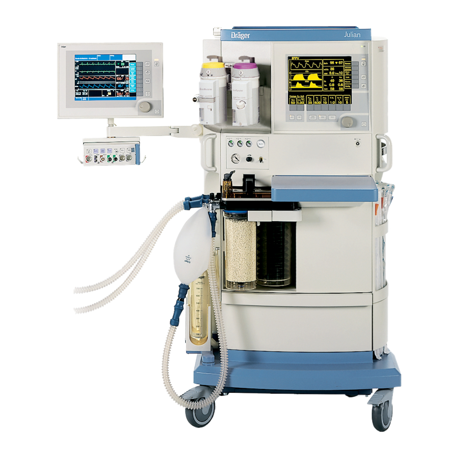
Page 126: Front View
What's what What's what Front view Screen with user interface 10 Compact breathing system Rotary knob for selection, setting and confirmation 11 Gas supply panel Main power switch 12 Vapors with interlock system Writing top 13 Mounting rail for accessories Catch to unlock the breathing system 14 Shelf for patient monitor Bellows... -
Page 127: Gas Supply Panel
What's what Gas supply panel kPa x 100 kPa x 100 kPa x 100 Safety-O Vac. L/min flush emergency metering Secretion aspiration on/off switch Rotary knob for secretion aspiration suction Secretion aspiration pressure gauge Central gas supply O pressure gauge Central gas supply AIR pressure gauge Central gas supply N O pressure gauge... -
Page 128: Screen With User Interface
What's what Screen with user interface IPPV Pleth alarm limits CO 2 auto set limits etCO freq alarm info list 12... curves Hal. config. Freshgas O Freq. PEEP mbar 1/min mbar L/min 4.00 IPPV SPONT Status field showing the current ventilation mode 10 Softkeys for setting ventilation Curve field for curves and bar graphs 11 Power supply indicator... -
Page 129: Rear View
What's what Rear view Gas supply ports Anaesthetic gas scavenging system AGS Sample gas return with filter Power cable sensor (behind the sealing screw) Cooling air filters Interface panel Connection for sample line with water separator and water trap Bacterial filter for suction system Auxiliary power sockets Waste gas connector Pin for earth cable... -
Page 130: Interface Panel
What's what Interface panel Analog Sync. COM 3 CAN 2 CAN 1 COM 2 Temp. COM 1 SA-Bus 9 10 Analog Analog output for three curves COM3 RS232 interface for MEDIBUS COM2 RS232 interface for MEDIBUS COM1 RS232 interface for printer SA-Bus For DrägerService only CAN1... -
Page 131: Technical Data
Technical Data Contents Technical Data Contents Ambient conditions................132 Fresh gas....................132 Ventilator....................132 Breathing system..................133 Measuring systems................133 Pressure measurement ................133 measurement..................133 Flow measurement................. 134 Airway temperature measurement............134 measurement................. 134 Anaesthetic gas measurement..............135 measurement................135 C-Lock-ECG synchronization (optional)..........136 Interfaces....................136 Operating data.................. -
Page 132: Ambient Conditions
Technical Data Technical Data Ambient conditions In operation: 10 to 35 °C Temperature Air pressure 700 to 1060 hPa Rel. humidity 20 to 80 % (no condensation) concentration of ambient air 300 to 800 ppm In storage: –20 to 60 °C Temperature sensor max. -
Page 133: Breathing System
Technical Data Breathing system Total gas volume Approx. 4.5 L enclosed gas volume Compliance with filled absorber container, without breathing hoses Approx. 4.5 mL/mbar Absorber volume 1.5 L Leakage (EN 740) <150 mL/30 mbar Pressure limiting valve APL Adjustment range 5 to 70 mbar ±15 % of setting Exp. -
Page 134: Flow Measurement
Technical Data Flow measurement (hot wire anemometry) Tidal volume VT Range 0.02 to 9.99 L Resolution 0.01 L Better than ±8 % of the measured value or 0.01 L, the larger value Accuracy (under calibration conditions and 1013 hPa) applies Minute volume MV Range 0 to 99.9 L/min... -
Page 135: Anaesthetic Gas Measurement
Technical Data Anaesthetic gas measurement (infrared spectrometry) Sample rate (selectable) 60 mL/min or 200 mL/min Delay time for sampling Less than 1 s Display range for N 0 to 100 vol% Better than ±2.5 vol% absolute or 4 % of measured value Accuracy Resolution 0.1 vol%... -
Page 136: C-Lock-Ecg Synchronization (Optional)
Technical Data Sensors Type Compatible with Nellcor sensors Oxisensor, Oxiband and Durasensor Wavelengths 660 nm (red) 920 nm (infrared) Acoustic pulse signal A tone is produced for each detected pulse, tone pitch proportional to oxygen saturation C-Lock-ECG synchronization (optional) Requirements for ECG synchronization signal Pos. -
Page 137: Operating Data
MV ±1 L/min AIR or O Operation Standby and MAN/SPONT 0 L/min Dimensions of Julian W x H x D 68 cm x 133 cm x 68 cm Dimensions of the storage tray W x D 43 cm x 29 cm... -
Page 139: Abbreviations / Symbols
Abbreviations / Symbols Contents Abbreviations / Symbols Contents Abbreviations..................140 Symbols ....................141... - Page 140 Abbreviations Abbreviations Abbreviation Meaning Abbreviation Meaning AGas Anaesthetic gas MAN/SPONT Manual ventilation / spontaneous breathing Anaesthesia Gas Scavenging System MEAN Mean pressure Compressed air for medical use Expiratory minute volume Adjustable Pressure Limitation Nitrous oxide (laughing gas) BTPS Measuring condition at body temperature, current atmospheric pressure and NiBP Non-invasive blood pressure...
- Page 141 Symbols Symbols Symbol Meaning Suppress alarm tone for 2 minutes Call up standard page Call up basic pages in succession Standby / operation switch ª Pulse rate Fresh gas flowing Action in progress Action has been completed successfully Repeat calibration Upper and lower alarm limits >...
-
Page 142: Index
Index Index bbreviations ............140 COM3 ..............85 Absorber, dismantling ..........99 Compliance ............32, 133 Absorber, filling and installing ......... 107 Configuring in operation ........... 68 Accessories ..............5 Configuring in standby ..........82 Advisory ............63, 120 Connection ..............5 Airway temperature measurement ...... - Page 143 Index aintenance ............5, 116 Standby ............. 47, 54 Maintenance intervals ..........116 Starting up ............26, 33 Major hardware fault ..........53 Sterilization ............. 102 MAN/SPONT ............37 Suction rate .............. 84 Manual calibration ..........75, 92 Switch-off time lag ............ 54 Manual ventilation .............
- Page 144 These Instructions for Use apply only to Julian with Serial No.: If no Serial No. has been filled in by Dräger these Instructions for Use are provided for general information only and are not intended for use with any specific ç...
Need help?
Do you have a question about the Julian and is the answer not in the manual?
Questions and answers