Table of Contents
Advertisement
Quick Links
Advertisement
Chapters
Table of Contents

Related Manuals for Dräger Julian


Summary of Contents for Dräger Julian
- Page 1 Julian Anesthesia Workstation Operating Instructions Software 3.n...
- Page 2 NOTICE Proprietary Information This document contains information in which Dräger claims proprietary rights. The information may not be reproduced in whole or in part except as authorized in writing by Dräger. This information is the property of Dräger, it is provided solely for the use intended. Repairs/Modifications Repairs on this device shall be performed only by Dräger Service or its Authorized Service Centers.
- Page 4 Observe all WARNINGS and CAUTIONS as rendered throughout this manual and on labels on the equipment. NOTE: If you wish to read these instructions without the Julian Anesthesia Workstation in front of you, you may want to keep the full page photo folded out.
- Page 5 Contents Contents Important Safety Information READ THIS FIRST ! Intended Use Operating Concept Preparation Operation Monitoring Configuring in Standby Mode Care Troubleshooting What's What Technical Data Index...
- Page 6 Operating Instructions Julian SW 3.n...
-
Page 7: Table Of Contents
Important Safety Information Contents Important Safety Information Contents Operator's Responsibility for Patient Safety..........8 Limitation of Liability..................8 Warranty..................... 9 Definitions....................10 Abbreviations.................... 10 Symbols....................11 Definitons of Terms................... 11 Typing Conventions...................11 Summary of WARNINGS and CAUTIONS..........12 General Precautions..................12 Precautions During Preparation.............. -
Page 8: Operator's Responsibility For Patient Safety
Important Safety Information Operator's Responsibility for Patient Safety Limitation of Liability Operator's Responsibility for Patient Safety Limitation of Liability For correct and effective use of the product and in Dräger's liability, whether arising out of or related to order to avoid hazards, it is mandatory to carefully manufacture and sale of the goods, their installation, read and to observe all portions of this manual. -
Page 9: Warranty
Important Safety Information Warranty Warranty All Dräger products are guaranteed to be free of defects Application of this warranty is subject to the following for a period of one year from date of delivery. conditions: The following are exceptions to this warranty: 1. -
Page 10: Definitions
Dräger communications protocol for temperature, current atmospheric medical equipment pressure and saturated gas (Expiratory) minute volume ç Conformité Européenne Julian conforms to the respective EC Nitrous oxide (laughing gas) requirements NiBP Non-invasive blood pressure C-Lock The SpO signal is synchronized with the... -
Page 11: Symbols
Definitions Symbols Definitions of Terms Typing Conventions Symbols Definitions of Terms Symbol Meaning WARNING ! Suppress alarm tone for 2 minutes A WARNING statement refers to conditions with a possibility of personal injury if Call up standard screen + escape disregarded. -
Page 12: Summary Of Warnings And Cautions
Equipment malfunction may result. WARNING ! WARNING ! Do not use accessories with the Julian Anesthesia Workstation that are not listed in The Julian Anesthesia Workstation may only the component overview document enclosed be used under the supervision of qualified with the device. -
Page 13: Precautions During Preparation
Only use Dräger Vapor 19.3 or Vapor 2000 failure of a protective ground conductor. with Julian Anesthesia System. In such cases, the risk of electric shock cannot be excluded. Additional power strips must not be connected WARNING ! to the auxiliary outlets. -
Page 14: Precautions During Operation
WARNING ! WARNING ! Absorbent is caustic and is a strong irritant to Manual ventilation is not possible when Julian the eyes, skin, and respiratory tract. When is in standby mode! emptying absorber, take care not to spill its... -
Page 15: Precautions During Maintenance
Do not treat exterior surfaces of the workstation obtaining a service contract through your vendor. with disinfecting agents containing alcohol. Maintenance or repair of the Julian Anesthesia Workstation shall be performed by DrägerService or an authorized representative of DrägerService. CAUTION ! Do not clean filter in cleaning and disinfecting equipment. - Page 16 This page intentionally left blank...
- Page 17 Intended Use Contents Intended Use Contents Intended Medical Applications..............18 Ventilation Modes and Monitoring.............. 18...
- Page 18 The Julian is indicated as a continuous flow anesthesia systems with "low flow" and "minimal flow" system. The Julian may be used for manually assisted, or techniques (for minimal gas and anesthetic agent automatic ventilation, and delivery of gases, anesthetic consumption) with a fresh gas flow of 0.5 to 12 L/min.
- Page 19 Operating Concept Contents Operating Concept Contents Design of the User Interface..............20 Screen Menus ..................22 Screen Layout ..................22 Ventilation Menus..................22 Monitoring Menus..................23 Three Basic Screens for Monitoring............25...
-
Page 20: Design Of The User Interface
Operating Concept Design of the User Interface Design of the User Interface All settings required for Monitoring – Fresh gas delivery – Ventilation alarm – Monitoring limits auto set limits EtCO Freq are entered on the system screen using the respective alarm info keys and the central dial knob. - Page 21 Operating Concept Design of the User Interface Complementary "menu" keys with variable functions are provided at the bottom edge of the screen, above each group of "hard" keys. These menu keys are alarm limits used to set fresh gas delivery and ventilation auto set limits EtCO...
-
Page 22: Screen Menus
Right-hand menu keys – for monitoring: For quick selection of desired monitoring function Ventilation Menus Selecting / setting ventilation parameters Julian Example: PEEP ventilation parameter 1 Press »PEEP« menu key. 2 Select PEEP value = turn dial knob. 3 Confirm the PEEP value = press the dial knob. -
Page 23: Monitoring Menus
L/min 4.00 1:2.0 SPONT Selecting / setting monitoring functions For example, to change the lower alarm limit of the Julian end-tidal CO concentration. 1 Press »alarm limits« menu key. The alarm limits menu will be displayed on the screen. Pleth... - Page 24 IP I L/min 1.00 600 10 1:2.0 To exit the alarm limits menu: Julian 1 Press the dial knob 2 Press the key. The function keys for standard functions are located on the right-hand side of the control panel. alarm limits Suppress audible alarms for 2 minutes.
-
Page 25: Three Basic Screens For Monitoring
Operating Concept Screen Menus Three Basic Screens for Monitoring Julian To call up the standard screen, data screen and trend screen in succession: 1 Briefly press the key until the desired screen is displayed. Back to the standard screen: 2 Press the key. - Page 26 Operating Concept Screen Menus The trend screen displays recorded progress of numerical values over time alarm since measurement started. The current measured values limits are displayed on the right-hand side. Freq Display (example): agent 11:00 12:00 13:00 Trends for CO and minute volume MV.
- Page 27 Preparation Contents Preparation Contents Before Using for the First Time............... 28 Charging the Battery for Emergency Operation..........28 Assembly of Components................29 Installing the Breathing Circuit..............29 Preparing the Suction System..............30 Preparing Gas Disposal Systems...............31 Connecting Supplies ................33 Gas Connections..................33 Anesthetic Gas Scavenging System............
-
Page 28: Before Using For The First Time
The battery must be charged for 10 hours before using for the first time. Connect power plug of the Julian workstation to a live wall outlet. The line voltage must correspond to the voltage specified on the rating plate. -
Page 29: Assembly Of Components
Preparation Assembly of Components Assembly of Components WARNING ! Always install parts that have been cleaned and disinfected! For assembly and installation of the breathing system, bellows, and absorber system, please refer to page 117, "Assembly". Installing the Breathing Circuit 1 Connect the limbs of the breathing hoses to the Y- piece and to the ports of the breathing system. -
Page 30: Preparing The Suction System
(infectious waste). Prepare secretion collecting canisters and hose system according to manufacturer's instructions for use for the suction unit. 1 Attach vacuum hose to the VAC port of the Julian Workstation. -
Page 31: Preparing Gas Disposal Systems
Preparation Assembly of Components Preparing Gas Disposal Systems Waste gas connector 1 Slide the tube into the port and tighten it. 2 Connect the small silicone hose to the mixer exhaust gas port and to the connection on the tube. - Page 32 Preparation Assembly of Components Sample gas scavenging Use hose 11 90 520, connector M 33 151 and sealing cap (optional). 1 Connect the hose to the port of the sample gas outlet port. 2 Attach connector with sleeve to the free end of the hose.
-
Page 33: Connecting Supplies
Ensure that the gas pressures of the gas supply pipeline are between 270 and 550 kPa (39 psi and 80 psi): 2 All pipeline pressure displays must be in the specified range. The pressure displays light up when the Julian workstation is connected to line power. - Page 34 Gas Connections Connecting backup gas cylinders for O and N Even if Julian is connected to a gas supply pipeline, the cylinders must remain on the workstation as backup supply. On the back of the workstation: place full tanks ( E-size) in the cylinder holders and secure in position.
-
Page 35: Anesthetic Gas Scavenging System
Preparation Connecting Supplies Anesthetic Gas Scavenging System Anesthetic Gas Scavenging System (Open Reservoir Scavenger) NOTE: The open reservoir scavenger is intended for use with suction (vacuum) waste gas disposal systems. This approach to scavenging applies continuous suction to transfer waste gas from the scavenger to the disposal system. -
Page 36: Electrical Connections
Preparation Connecting Supplies Electrical Connections Electrical Connections Auxiliary electrical systems 1 Connect to one of the auxiliary power outlets on the back of the workstation. WARNING ! Devices connected to auxiliary power outlets will not be powered by the uninterruptible power supply in the event of a power failure. -
Page 37: Checks Of Readiness For Operation
33 to 36 and assembled ready for operation as described on pages 29 to 32 and 116 to 117. The gas supply and power supply must be connected. Switch on Julian: press the power switch » «. After approximately 10 seconds, the opening screen appears displaying the current software version. - Page 38 WARNING ! ® Only use Dräger Vapor 19.3 or Vapor 2000 with Julian Anesthesia System. For safe filling procedure, please refer to Operating Instructions of the respective Vapor. 1 Ensure that handwheel is set to "0" and engaged. 2 Filled to sufficient level.
- Page 39 Checks of Readiness for Operation Breathing system Complete and engaged, with both valve discs inserted, bellows installed and hoses securely connected. Absorbent charge renewed, no purple discoloration. Gas pressures of the gas supply pipelines 1 All pressure displays within the specified range. Julian...
- Page 40 Check the cylinder pressure displays: pressure greater than 5000 kPa (725 psi), O pressure greater than 3000 kPa (435 psi). Suction system Julian 1 Switch to I. 2 Set suction pressure with dial knob. 3 Block the secretion probe adapter or kink the suction hose.
- Page 41 2 The breathing bag fills up. 1 Set Safety O back to » 0 «. Preparing Julian for the self test 1 Close the Y-piece = plug firmly onto the cone. 2 Ensure that the sample line is not connected to the patient circuit.
- Page 42 The self test is started. Duration: 3 to 4 minutes. The self test is performed automatically. 1 Julian essentially carries out the following automatic tests and actions, which are coded: The following list gives an overview of the main steps...
- Page 43 The system compliance and the leakage of the breathing electronics system cancel compliance 5.00 mL/mbar system and breathing circuit are determined by Julian in test the self test. freshgas leakage 16 mL/mbar mixer Depending on the patient circuit used, system...
-
Page 44: Emergency Startup
NOTE: To prevent abuse of this feature, the self test can only be cancelled 10 times in succession. The self test cannot be cancelled the next time that Julian is started and a complete self test must be performed. The system switches to standby mode after completing the minimal test. - Page 45 Operation Contents Operation Contents Setting Fresh Gas Concentrations............46 Selecting Ventilation Modes..............47 MAN/SPONT Ventilation Mode..............47 CMV Ventilation Mode................50 PCV Ventilation Mode................53 ® Setting Vapor ..................56 Aspirating Secretions................56 At the End of Each Anesthesia Case............57 Changing Absorber Charge..............57 Leak Test....................58 Ventilating Children..................59 Auxiliary Oxygen Flowmeter..............
-
Page 46: Setting Fresh Gas Concentrations
– »Fresh gas O O« or Standby »Fresh gas O + AIR« – O concentration »O %« Julian leak test – Fresh gas flow »L/min« 03.00 delete 01.May 00 The settings correspond to the default values trend configurable after switching on and after entering config. -
Page 47: Selecting Ventilation Modes
O value is highlighted in addition to the active menu key »L/min«. Julian is able to detect fresh gas deficiency . An opti- cal system monitors the end-expiratory position of the bellows. If the bellows is not filled sufficiently during expiration, the alarm 'FRESH GAS? !' appears. - Page 48 Operation Selecting Ventilation Modes 1 Press »MAN/SPONT« key, Julian 2 and confirm with the dial knob. MAN/SPONT Display (example): Pleth alarm limits -al. FiCO on/off etCO freq alarm info list curves 0.35 Iso. Volumeter --s config. Enf. MAC (age: 36)
- Page 49 Operation Selecting Ventilation Modes Certain alarms are automatically switched off in MAN/SPONT ventilation mode in order to avoid nuisance alarms. Disabled alarms are identified by a gray back- ground in the table below. Alarm Limits In MAN/SPONT Factory default mode setting –...
-
Page 50: Cmv Ventilation Mode
Operation Selecting Ventilation Modes CMV Ventilation Mode Julian CMV = Continuous Mandatory Ventilation Volume-controlled ventilation with fixed mandatory minute volume (MV), set with the tidal volume (V and the respirtory rate (Freq.). Presetting the ventilation parameters for CMV 1 Press »CMV« key; its LED will start flashing. - Page 51 200 mL: Use a pediatric patient circuit, see page 59 "Ventilating Children". In CMV mode, Julian will automatically compensate for the compliance of the breathing system and hoses. This ensures that the delivered tidal volume corresponds to the volume setting. In some cases,...
- Page 52 Operation Selecting Ventilation Modes Alarms effective in CMV mode: Factory default Alarm Limits In CMV mode setting – – ª Pulse EtCO 50 mmHg – – FiCO 5 mmHg > – – – – Fi Hal. – – Fi Iso. –...
-
Page 53: Pcv Ventilation Mode
PCV = Pressure Controlled Ventilation In pressure controlled ventilation mode, the applied tidal volume depends on the ventilation parameters Julian Pmax and PEEP as well as on lung compliance. Changes in ventilation parameters or lung compliance influence tidal volume. Minute volume (MV or V ) must therefore be monitored continuously. - Page 54 Operation Selecting Ventilation Modes Starting PCV Julian 1 Press »PCV«. 2 Confirm by pressing the dial knob. Display (example): alarm limits auto set limits Freq alarm info The preset ventilation parameters appear on the screen. list curves 0.35 Iso. Volumeter config.
- Page 55 Operation Selecting Ventilation Modes Alarms effective in PCV mode: Alarm Limits In PCV mode Factory default settings – – ª Pulse EtCO 5 mmHg – – FiCO 5 mmHg > – – – – Fi Hal. – – Fi Iso. –...
-
Page 56: Setting Vapor
2 Press the » O « button and 3 set the handwheel to the required anesthetic agent concentration. Aspirating Secretions Julian Swing the suction system forwards. 1 Set switch to » I «. 2 Seal the secretion probe adapter or kink the suction... -
Page 57: At The End Of Each Anesthesia Case
Operation At the End of Each Anesthesia Case Changing Absorber Charge At the End of Each Anesthesia Case To switch Julian to standby: Press Standby key and confirm with the dial knob. Standby The functions of the workstation are switched off. -
Page 58: Leak Test
3 If necessary, seal the sample-line connector with a luer-lock cap. Press the softkey »leakage« in standby mode. Julian performs the leak test for CMV/PCV and determines the volume correction for system compliance, duration approx. 30 seconds. The breathing bag and its hose are not included in the test. -
Page 59: Ventilating Children
Operation Ventilating Children Ventilating Children For tidal volumes V of less than 200 mL: Use pediatric breathing circuit Connecting the breathing circuit 1 Connect 0.5 L breathing bag with connector to the breathing hose with the large connection sleeves. Slip breathing hose over the elbow connector. Hang breathing bag onto the hook. -
Page 60: Auxiliary Oxygen Flowmeter
(e.g., delivery through a nasal cannula), an optional auxiliary oxygen flowmeter can be mounted on the left side of the Julian workstation (see page 130, What's What). This flowmeter can also be used when the anesthesia machine is turned off. -
Page 61: In The Event Of Supply Failures
Check pressure display for the backup gas cylinder Reestablish supply from pipeline. If there is no backup supply of gas available, Julian replaces the set gas mixture with AIR or O Julian delivers 100 % AIR if the O supply fails. -
Page 62: In The Event Of A Major Hardware Fault
Fresh gas metering is still possible even in the event of failure of one of the gases. For example, if the N supply fails, AIR can be selected as the carrier gas. Julian is equipped with two independent gas supply failure alarm systems. If the supply pressure of O... -
Page 63: End Of Operation
The system is switched off after 10 seconds. Remove gas supply probes from the wall terminals. Leave Julian connected to line power in order to keep charging the uninterruptible power supply (UPS). In case of mains power supply failure, the power switch should always be switched off. - Page 64 This page intentionally left blank...
- Page 65 Monitoring Contents Monitoring Contents Selecting the Basic Screen Pages............66 Selecting the Standard Screen Page............66 Selecting the Data Screen Page..............67 Selecting the Trend Page................67 The Alarm System..................69 Displaying and Setting Alarm Limits............70 Auto-Set Limits..................72 Alarms On/Off.................. 72 Alarm Info....................73 Numerical Trend (List)................
-
Page 66: Selecting The Basic Screen Pages
Iso. their operating temperature. config. Enf. In this way, Julian indicates that data accuracy is still MAC (age: 36) compromised when compared to the specifications in the "Technical Data" section. The sensors can be Fresh Gas O + N O Freq. -
Page 67: Selecting The Data Screen Page
Monitoring Selecting the Basic Screen Pages Selecting the Data Screen Page Press key several times until the data page appears. PEAK cmH O alarm 1/min Display (example): limits PLAT cmH O auto set PEEP cmH O Compilation of all numerical values with their units of limits mmHg measurement. - Page 68 To delete trend memory NOTE: Deleting the trend memory is possible in standby mode only. The numerical and graphical Standby trend are deleted together! When in standby mode: Press »delete trend« menu key. Julian leak test 03.00 delete 01.May 00 trend config.
-
Page 69: The Alarm System
The Alarm System The Alarm System Alarm messages are assigned to three priority classes by Julian, depending on their urgency, and identified by exclamation marks: !!! Warning = Category I / High Priority Message A high priority alarm is a signal which indicates a condition requiring immediate action. -
Page 70: Displaying And Setting Alarm Limits
Monitoring The Alarm System Audible alarms can be silenced for two minutes: Julian NOTE: A new alarm condition during this period will still be signaled with an audible alarm. 1 Press key and its yellow LED will light up. To reactivate audible alarm: 1 Press key and its yellow LED will go out. - Page 71 Monitoring The Alarm System imits Example EtCO Upper alarm limit (42 mmHg) and lower alarm limit alarm info (30 mmHg) are shown alongside the measured value (38 mmHg). A disabled alarm limit is indicated by two dashes (– –). Disabled CO alarms are indicated by a symbol in the measurement field.
-
Page 72: Auto-Set Limits
Method 2: The measured value of the last breath. Julian sets the upper alarm limit for PAW to the absolute higher determined measured value of – PEAK + 5 mbar or – P... -
Page 73: Alarm Info
Monitoring The Alarm System Alarms On/Off MAN/SPONT The alarm limits for EtCO , insp. CO and CO apnea Pleth. alarm monitoring can be switched off with the limits menu key »CO2-al. on/off« in MAN/SPONT mode. CO al. on/off Freq alarm In this case, the CO symbol appears alongside info... -
Page 74: Numerical Trend (List)
Delete trend and list NOTE: Deleting the trend memory is possible in standby mode only. The numerical and graphical trend are deleted together! Standby When in standby: Press »delete trend« menu key. Julian leak test 03.00 delete 01.May 00 Delete trends and list: trend config. -
Page 75: Selecting Waveforms
Monitoring Selecting Waveforms Selecting Waveforms NOTE: Selecting waveforms is only possible from the standard screen! This menu allows the user to select and position three waveforms (curves) for the current ventilation mode. The following curves can be selected: AGas anesthetic agent concentration at the Y-piece concentration at the Y-piece Flow... -
Page 76: Using The Volumeter Function
Monitoring Using the Volumeter Function Select the desired position with the dial knob and press to confirm. Pleth. alarm Display (example): limits The waveform is replaced and the cursor returns to auto set limits z z z z Freq symbol in the selection menu. alarm info To return to the standard page:... -
Page 77: Configuring During Operation
(optional) and settings in the parameter menu Iso. remain valid until Julian is switched off. config. Enf. MAC (age: 36) From standard screen (example) or data screen: Press »config.« menu key. -
Page 78: Setting Monitoring Functions
Monitoring Configuring During Operation Setting Monitoring Functions Select »settings« column by turning dial knob, press to confirm. Display (example): MAC-config. alarms calibration settings -Sensor MAC display default pulse tone 0 1 2 3 4 6 7 8 9 21 Vol.% alarm sound 1 2 3 5 6 7 8 9... - Page 79 Monitoring Configuring During Operation Setting the measuring parameters Select the line »parameters« with dial knob, press to confirm. The »parameters« menu appears in the left-hand field. Display (example): anesth. agent alarms calibration settings pls. tone 0 1 2 3 4 6 7 8 9 alarm sound 1 2 3...
- Page 80 These values are read from an Freq. T :T PEEP IP I L/min cmH O cmH O external monitor which is connected to Julian via 1.00 600 10 1:2.0 MEDIBUS interface. If no Dräger NiBP monitor is connected, no NiBP entries will be activated. warning-started An entry is made whenever a Warning message is triggered.
-
Page 81: Configuring Alarms
Monitoring Configuring During Operation Configuring Alarms Turn dial knob to select the column »alarms«, press to confirm. Default This function is used to activate default alarm limits set in the standby configuration which are effective whenever the system is switched to standby. Setting default alarm limits: Turn dial knob to select »defaults«... - Page 82 HLM alarm mode. The HLM mode of Julian is dependent on the alarm system or functionality of the connected HLM machi- ne and is not intended to replace any monitoring or alarms of the HLM machine.
-
Page 83: Mac Configuration
Monitoring MAC configuration MAC configuration Anesthetic agent identification and display alarm limits Julian automatically identifies the anesthetic agent used auto set limits and adjusts the measurement and monitoring of the Freq alarm anesthetic gas concentration to suit the gas identified. - Page 84 Monitoring MAC configuration To select the patient's age: MAC-config. alarms calibration settings Select line »age« by turning the rotary knob and press to confirm. MAC display default -Sensor pulse tone 0 1 2 3 4 6 7 8 9 21 Vol.% alarm sound 1 2 3 5 6 7 8 9...
-
Page 85: Manual Calibration
Monitoring Manual Calibration Manual Calibration Julian calibrates its sensors automatically during operation. The message CAL appears instead of the MAC-config. alarms calibration settings current measured value during a calibration process. Calibration of the O sensor and zero calibration of -Sensor... -
Page 86: Spo 2 Measurement (Available Option)
Monitoring Measurement Measurement (Available Option) Sensor Selection WARNING ! Use only original Nellcor SpO sensors. Follow Instructions for Use of the sensors – incorrect positioning or use can cause tissue damage. Select sensor according to the following criteria: – Patient weight –... -
Page 87: C-Lock Ecg-Synchronization
– An optical signal from the SpO sensor monitor – an electrical signal from the separate ECG monitor. Julian uses the R-wave of the ECG signal to identify the pulse and to synchronize SpO measurement with this signal. 2 Route ECG signal from an ECG monitor with cable and plug to the back of the Julian. -
Page 88: Tips To Prevent Artifacts
Monitoring Measurement Tips to Prevent Artifacts Only use Nellcor-compatible sensors in the recommended positions, otherwise incorrect measurements and tissue damage may result. Damaged sensors with exposed electrical contacts must not be used – danger of electric shock. Used adhesive strips of the Oxiband-OXI-A/N and OXI- P/I sensor must not be reused, as they may not adhere properly. -
Page 89: Applying The Durasensor Ds-100 A
Monitoring Measurement Applying the Durasensor DS-100 A Reusable sensor for short-term monitoring of relatively immobile patients weighing over 40 kg. The sensor is preferably positioned on the index finger, although other fingers can also be used. The little finger should be used if the patient is particularly large or obese. -
Page 90: Airway Temperature Monitoring (Available Option)
Monitoring Airway Temperature Monitoring Airway Temperature Monitoring (Available Option) Required parts – Temperature sensor 84 05 371, – Y-piece with temperature sensor receptacle M 30 543 – T-piece 86 00 224 – Filter 86 00 225 1 Connect Y-piece with temperature sensor receptacle to breathing circuit. - Page 91 Configuring in Standby Mode Contents Configuring in Standby Mode Contents Setting Default Values................92 Setting Volume of the Pulse Tone (Optional)..........93 Setting Audible Alarm Volume..............93 Selecting the Scale................... 93 Setting Measuring Parameters..............94 Record...................... 95 Configuring the Interfaces................. 95 Setting Default Alarm Limits...............96 Configuring Waveforms (Traces)...............
-
Page 92: Setting Default Values
The basic configurations (language, time, date, and tone sequence) remain until their next modification. After switching the system on, the selection of anesthetic agent is always set to "auto". Switch Julian to standby mode. Press »config.« menu key. Display (example): Standby / Configuration MAC-config. -
Page 93: Setting Volume Of The Pulse Tone (Optional)
Configuring in Standby Mode Setting Default Values Turn dial knob to select digits consecutively from the Standby / Configuration line provided and press to confirm. The password is defaults MAC-config. calibration indicated underneath with asterisks ( * * * * ). The menu for selecting default settings appears when MAC display pls. -
Page 94: Setting Measuring Parameters
Configuring in Standby Mode Setting Default Values Setting Measuring Parameters Select the line »parameters« with dial knob, press to confirm. The »parameters« menu appears in the left-hand field. Display (example): Standby / Configuration MAC-config. calibration defaults pls. tone 0 1 2 3 4 6 7 8 9 measurement alarm sound... -
Page 95: Record
These values are read from an NiBP started CMV settings warning started PCV settings external monitor connected to Julian via MEDIBUS* caution started Fresh Gas Flow Control interface. Configuration Menu for List and Printer Entries. If no Dräger NiBP monitor is connected, no NiBP entries will be activated. -
Page 96: Setting Default Alarm Limits
Configuring in Standby Mode Setting Default Values Interface Choice between configuration of COM2 or COM3. Baud rate Transmission rate (variable, see Instructions for Use of the equipment to be connected). Parity This display is fixed for MEDIBUS and is shown for information purposes only. - Page 97 Configuring in Standby Mode Setting Default Values Adjustment range for default alarm limits: Alarm limits Adjustment range Factory default 51 to 100 – – 50 to 99 ª Pulse 31 to 300 [1/min] 30 to 299 EtCO 1 to 75 [mmHg] 0 to 74 –...
-
Page 98: Configuring Waveforms (Traces)
Configuring in Standby Mode Setting Default Values Configuring Waveforms (Traces) Three standard waveforms can be configured for each of the ventilation modes: MAN/SPONT, CMV and PCV. Turn dial knob to select the line »curves«, press to confirm. The selection menu appears in the left-hand field. Display (example): Standby / Configuration MAC-config. -
Page 99: Setting Basic Configurations
Configuring in Standby Mode Setting Default Values Setting Basic Configurations for time, date, language and alarm tone sequence. Turn dial knob to select the line »basic configurations«, press to confirm. The selection menu appears in the left-hand field. Display (example): Standby / Configuration MAC-config. -
Page 100: Cmv Default Settings
Configuring in Standby Mode Setting Default Values CMV Default Ventilation Settings Select and confirm the line »CMV default settings« with dial knob. The menu keys for CMV are displayed: Display (example): Standby / Configuration MAC-config. defaults calibration MAC display pls. tone 0 1 2 3 4 6 7 8 9 O -sensor... -
Page 101: Setting Fresh Gas Defaults
L/min 2.00 To modify settings: 1 Press keys »N O« or »AIR« to select default carrier gas, press dial knob to confirm. Julian 2 Press »O %« menu key. Set default O concentration with dial knob, press to confirm. 3 Press »L/min« menu key. -
Page 102: Manual Calibration
Use a separate O source, e.g. O flowmeter. from the Julian breathing system is not suitable, as it will still contains traces of anesthetic gas. Unscrew sample line from the Y-piece and place it in the continuous flow of the O source. -
Page 103: O 2 Linearity Test
(replace O sensor, see page 119). MAC configuration Anesthetic agent identification and display Julian automatically identifies the anesthetic agent used alarm limits and adjusts the measurement and monitoring of the auto set anesthetic gas concentration to suit the gas identified. -
Page 104: Displaying Mac
Monitoring MAC configuration Displaying MAC MAC-config. alarms calibration settings To activate the MAC display: Select column »MAC-config.« by turning the rotary MAC display default -Sensor pulse tone 0 1 2 3 4 6 7 8 9 21 Vol.% alarm sound 1 2 3 5 6 7 8 9 knob and press to confirm. - Page 105 Disassembly................... 108 Dismantling the Suction System............... 107 Dismantling the Breathing System............107 Anesthesia Gas Scavenging System AGS..........109 Disinfecting/Cleaning/Sterilizing............111 Care List for Julian Anesthesia Workstation...........114 Assembly....................116 Assembling the Breathing System............116 Maintenance................... 118 Maintenance Intervals................118 Cleaning/Replacing Cooling Air Filters............. 119 Replacing Water Trap................
- Page 106 Care Disassembly Disassembly WARNING ! Always follow accepted hospital procedures for handling equipment contaminated with body fluids. Unscrew sample line from Y-piece and from water trap on the back of the unit. The sample line is not reusable and it can be disposed of together with ordinary domestic waste.
-
Page 107: Dismantling The Suction System
Care Disassembly Do not damage breathing hoses! CAUTION ! When removing and connecting breathing hoses, always hold by the connector cuff and not by the spiral reinforcement, otherwise the reinforcing spiral may be torn off the cuff. Breathing hoses with damaged spirals can easily be kinked and may interrupt ventilation! Always check the breathing hoses for damage prior to use. -
Page 108: Disassembly
Care Disassembly Removing the flow sensor 1 Unscrew expiratory port. 2 Remove flow sensor. CAUTION ! Do not process flow sensor in cleaning and disinfection equipment or steam-autoclave flow sensor. Do not use compressed air, a brush or similar tools to clean flow sensor as this could possibly damage the thin wires inside. -
Page 109: Anesthesia Gas Scavenging System Ags
Care Disassembly Opening the breathing system – Weekly 1 Loosen the five sealing screws a quarter-turn with the key supplied. Remove cover. 2 Remove the two valve discs. Lift off the metal valve plate. Keep valve discs in a cassette to protect them against damage and prepare them for cleaning and disin- fection in a parts washing/disinfection unit. - Page 110 Care Disassembly Waste gas connector 1 Disconnect the small silicon hose from the waste gas tube, 2 pull the waste gas tube out. Prepare the waste gas connector for cleaning and disinfection in a parts washing/disinfection unit.
-
Page 111: Disinfecting/Cleaning/Sterilizing
Care Disinfecting/Cleaning/Sterilizing Disinfecting/Cleaning/Sterilizing Clean and sterilize the Julian Anesthesia Workstation and its parts according to the guidelines below. Follow your institution's policies regarding specific methods and agents for cleaning and sterilization. Determination of the need and frequency of sterilization of any particular component is the responsibility of the user institution. - Page 112 – risk of corrosion! can be sterilized in a steam-autoclave at 134 °C (273 ºF). Surfaces of Julian, gas supply hoses, cables and Vapor 19.3 / Vapor 2000 . CAUTION ! Do not treat exterior surfaces of the workstation with disinfecting agents containing alcohol.
- Page 113 Dispose of flow sensor as infectious special waste. It may be incinerated at temperatures of more than 800 °C (1472 ºF) NOTE: All components to be processed are listed in the care list for Julian on pages 114 and 115, together with their appropriate disinfection methods and intervals.
-
Page 114: Care List For Julian Anesthesia Workstation
Care List for Julian Anesthesia Workstation Only applies for non-infectious patients. When used with infectious patients, all parts in contact with breathing gas must additionally be sterilized after cleaning and disinfection. What How often Processing intervals Components which can be processed... - Page 115 The parts should preferably be cleaned and disinfected in a parts washing/disinfection unit, or by immersion. Julian and its components must not be treated with formaldehyde vapors or ethylene oxide! Sterilization Steam, 134 °C Washing machine Wiping Immersion 93 °C 10 minutes (273 ºF), 10 min.
-
Page 116: Assembly
Care Assembly Assembly Assembling the Breathing System 1 Place the bottom section on a flat surface. 2 Fit valve plate on top of the bottom section. 3 Insert both valve discs. 4 Tightly fit cover. 5 Tighten all five sealing screws a quarter-turn. 6 Hang breathing system into the slide-out module. - Page 117 Care Assembling Installing the bellows Hold breathing system from above to prevent it from dropping out and 1 uniformly slide the tightly compressed bellows onto the connector. 2 Insert bellows container into the breathing system from below and turn it clockwise as far as possible. Filling and installing the absorber unit 3 Push insert fully into the absorber.
-
Page 118: Maintenance
Must be replaced by professionals after four years. Must be disposed of in accordance with the local waste disposal regulations. The supplier will make circuit diagrams, component part lists, descriptions and calibration instructions available on request if needed for the maintenance of Julian. -
Page 119: Cleaning/Replacing Cooling Air Filters
Care Maintenance Cleaning /Replacing Cooling Air Filters – Clean filters monthly 1 Remove all three cooling air filters from their holders. Clean in warm water to which a detergent has been added; dry thoroughly. Insert cooling air filters into their holders without creasing. -
Page 120: Sensors
Care Disposing of Batteries and O Sensors Disposing of Batteries and O Sensors WARNING ! Treatment of batteries and O -sensor capsules: Do not throw into fire! Risk of explosion. Do not force open! Danger of bodily injury. Follow all local, state, and federal regulations with respect to environmental protection when disposing of batteries and O -sensor... - Page 121 Troubleshooting Contents Troubleshooting Contents Troubleshooting..................122...
- Page 122 Troubleshooting Troubleshooting Julian displays alarm messages at 3 levels of priority: In the table below, messages are listed in alphabetical (For definitions of alarm priority levels, see page 69) order. The table should help you to identify the cause of an !!! Warning = Message with top priority alarm and to ensure rapid remedy of the problem.
- Page 123 Troubleshooting Message Cause Remedy AW TEMP HIGH Breathing gas temperature above If using a breathing gas humidifier: 40 °C. disconnect humidifier. If using heated patient circuit: remove plug of circuit heater. BATTERY LOW Battery capacity of the uninterruptible Prepare manual ventilation with power supply is almost exhausted.
- Page 124 Check fresh gas setting. JULIAN COM 2 ? * Communication via RS 232 interface Check connector plugs on Julian and COM 2/COM 3 has been interrupted. the connected device. JULIAN COM 3 ? Minute volume exceeds upper alarm Correct tidal volume or respiration rate.
- Page 125 Troubleshooting Message Cause Remedy O SUPPLY ? O supply has failed. Open the N O backup cylinder. Supply pipeline connector is not Check connection to supply pipeline. plugged in or N O hose is kinked. Restore N O supply. O cylinder empty. Connect a full N O cylinder.
- Page 126 The ventilator control unit is perfor- Do not operate the system. ming an internal restart which takes about 30 seconds. Julian is then res- tored to its previous operating mode. VOL ALRM OFF * APNEA VOL or MIN VOL LOW alarm disabled.
- Page 127 What's What Contents What's What Contents Front View..................... 128 Screen with User Interface..............129 Gas Supply Monitoring Panel..............130 Rear View....................131 Interface Panel..................132 Anesthetic Gas Scavenging System............133 Labels....................134...
-
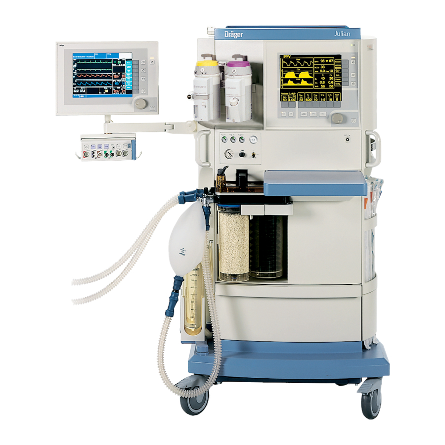
Page 128: Front View
What's What Front View Front View Screen with user interface 10 Compact breathing system Dial knob for selecting, setting, and confirming 11 Front panel for gas supplies, see page 130 Main power switch 12 Mounting rail for accessories Writing top 13 Vapors with interlock system Catch to unlock breathing system 14 Shelf for accessories... -
Page 129: Screen With User Interface
What's What Screen with User Interface alarm limits auto set limits EtCO Freq alarm info list 12... traces Iso. Enf. config. MAC (age 36) Fresh gas O Freq. PEEP L/min 4.00 1:2.0 SPONT Screen with User Interface Status field showing the current ventilation mode 13 Key for suppressing audible alarm for 2 minutes Graphic field for traces and bar graphs 14 Key for changing monitoring screen pages... -
Page 130: Gas Supply Monitoring Panel
What's What Gas Supply Monitoring Panel Gas Supply Monitoring Panel Pipeline pressue display Cylinder pressure display flush Safety O flow control On/Off switch for suction system Vacuum pressue adjustment valve Vacuum pressure gauge for suction... -
Page 131: Rear View
What's What Rear View Rear View Vacuum supply port Transfer hose to anesthetic gas scavenging system Gas supply ports 10 Anesthetic gas scavenging system AGS, sensor (behind the screw-mount sensor holder) see page 133 Connectors for cylinder pressure sensors 11 Power cable Interface panel, see page 132 12 Cylinder holders Waste gas connector... -
Page 132: Interface Panel
What's What Interface Panel Analog Sync. COM 3 COM 2 Temp. COM 1 SA-Bus Interface Panel Analog Analog output for three waveforms COM3 RS232 interface for MEDIBUS COM2 RS232 interface for MEDIBUS COM1 RS232 interface for printer SA-Bus For DrägerService only Temp Socket for temperature sensor, optional Socket for SpO... -
Page 133: Anesthetic Gas Scavenging System
What's What Anesthetic Gas Scavenging System (AGS) Anesthetic Gas Scavenging System (AGS) Receiving system head Socket for Gas-Disposal-Assembly tubing Flow adjustment valve Flow indicator with float showing scavenging flow Particulate filter Buffer container Socket for transfer hose Socket for second transfer hose, closed with screw Socket for sample gas scavenging hose... -
Page 134: Labels
What's What Labels Labels Label 1 DANGER ! POSSIBLE EXPLOSION HAZARD IF USED IN THE PRESENCE OF FLAMMABLE ANESTHETICS. DANGER ! RISQUE D'EXPLOSION EN CAS D'UTILISATION EN PRÉSENCE D'ANESTHESIONES INFLAMMABLES. Label 1 Label 2 CAUTION ! Label 2 DO NOT BLOCK AIR INTAKES. ATTENTION ! NE PAS OBSTRUER LES ENTRÉES D'AIR. - Page 135 Label 3 Label 4 Label 7 CAUTION ! Label 3 POSSIBLE TIP OVER HAZARD. REMOVE EQUIPMENT FROM Julian SHELF BEFORE MOVING ANESTHESIA MACHINE. ATTENTION ! RISQUE DE BASCULEMENT. ENLEVER L'APPAREIL DE LA TABLETTE AVANT DÉPLACER LA MACHINE. Label 4 MAX. 1.5 KG...
- Page 136 This page intentionally left blank...
- Page 137 Technical Data Contents Technical Data Contents Environmental Conditions.................138 Performance Data..................138 Measuring Functions................139 Interfaces....................142 Operating Data..................143 APL Valve Characteristics................144 Materials Used..................145...
-
Page 138: Environmental Conditions
Technical Data Environmental Conditions Performance Data Note: Specifications are given conforming to ISO 5369. Environmental Conditions In operation: 10 to 35 °C (50 to 95 °F) Temperature Air pressure 700 to 1060 hPa Rel. humidity 20 to 80 % (no condensation) concentration of ambient air 300 to 800 ppm In storage:... -
Page 139: Measuring Functions
Technical Data Performance Data Measuring Functions Breathing system Total gas volume (without breathing hoses) Approx. 4.5 L enclosed gas volume Compliance with filled absorber container, without breathing hoses Approx. 4.5 mL/mbar Absorber volume 1.5 L Leakage (EN 740) <150 mL at 30 mbar Pressure limiting valve APL Adjustment range 5 to 70 mbar... - Page 140 Technical Data Measuring Functions Flow measurement (hot wire anemometry) Tidal volume VT Range 0.02 to 9.99 L Resolution 0.01 L Better than ±8 % of the measured value or 0.01 L, the larger value Accuracy (under calibration conditions and 1013 hPa) applies Minute volume MV Range...
- Page 141 1 hour at 21°C should be observed. The accuracy of the measuring equipment used should be at least 5 times and if possible 10 times higher than that of Julian. Display range for N 0 to 100 vol% Resolution 0.1 vol%...
-
Page 142: Interfaces
Technical Data Measuring Functions Interfaces measurement, optional (light absorption) Display range 0 to 100 % SpO Accuracy (adults) Better than ±2 % SpO between 70 and 100 % SpO Better than ±3 % SpO between 50 and 70 % SpO between 0 and 50 % SpO Not specified Accuracy (neonates) -
Page 143: Operating Data
MV ±1 L/min AIR or O Operation Standby and MAN/SPONT 0 L/min Dimensions of Julian W x H x D 68 cm x 133 cm x 68 cm Dimensions of the storage tray W x D 43 cm x 29 cm... -
Page 144: Apl Valve Characteristics
Technical Data APL Valve Characteristics APL Valve Characteristics... -
Page 145: Materials Used
Technical Data Materials Used Materials Used Part Appearance Material flow sensor element yellow, transparent Polysulphone with hot wire pewter Platinum Hose connectors metallic, silver Brass CuZn37 F45, chromium plated Valve plate gray Aluminium AlMg3 G24, anodized Valve plate seals blue Silicone rubber Insp/exp. - Page 146 Index Index bbreviations............. 10 Configuring during standby.........91 Absorber, removing..........108 Cooling air filters, cleaning........119 Absorber, filling and installing........117 Advisory............. 69, 122 ata page............25, 67 Alarm info.............69, 73 Date................99 Alarm limits............70, 96 Default alarm limits, setting......... 96 Alarm volume, setting........... 78, 93 Default settings, fresh gas........
- Page 147 Index uclear spin tomography..........12 apor.................38 Vapor, setting............. 56 concentration, setting........... 46 Ventilation mode............47 flush............... 41, 48 Ventilation mode CMV..........50 sensor, replacing........119, 120 Ventilation mode MAN/SPONT........47 Operating concept............. 19 Ventilation mode PCV..........53 Operating, for the first time......... 28 Ventilation parameters for CMV........
- Page 148 These Operating Instructions apply only to Julian Anesthesia Workstation with serial no.: Without entry of a serial no. by Dräger these Operating Instructions are provided for general information only and are not intended for use with a specific device. Distributed by Manufactured by Dräger Medizintechnik GmbH...
Need help?
Do you have a question about the Julian and is the answer not in the manual?
Questions and answers