Advertisement
Quick Links
Advertisement
Troubleshooting

Related Manuals for Thermo Scientific TVA2020


Summary of Contents for Thermo Scientific TVA2020
- Page 1 TVA2020 Instruction Manual Toxic Vapor Analyzer Part Number 111755-00 29Jul2014...
- Page 2 © 2013 Thermo Fisher Scientific Inc. All rights reserved. Specifications, terms and pricing are subject to change. Not all products are available in all countries. Please consult your local sales representative for details. Thermo Fisher Scientific Air Quality Instruments 27 Forge Parkway Franklin, MA 02038 1-508-520-0430 www.thermoscientific.com/aqi...
-
Page 3: Weee Compliance
WEEE Compliance This product is required to comply with the European Union’s Waste Electrical & Electronic Equipment (WEEE) Directive 2002/96/EC. It is marked with the following symbol: Thermo Fisher Scientific has contracted with one or more recycling/disposal companies in each EU Member State, and this product should be disposed of or recycled through them. - Page 4 Thermo Fisher Scientific WEEE Compliance...
-
Page 5: About This Manual
About This Manual This manual provides information about installing, maintaining, and servicing the TVA2020 Toxic Vapor Analyzer (TVA). It also contains important alerts to ensure safe operation and prevent equipment damage. The manual is organized into the following chapters and appendices to provide direct access to specific operation and service information. - Page 6 To prevent a potential explosion, do not operate the instrument with the PID compartment open or FID ▲ detector cap removed. Power down the instrument before performing any ▲ service procedures. TVA2020 Instruction Manual Thermo Fisher Scientific...
- Page 7 Observe all hydrogen handling procedures listed below. ▲ Do not allow any contact with the igniter coil during ▲ cleaning. Equipment Damage Do not operate the TVA2020 if its case is damaged or ▲ otherwise compromised. Thermo Fisher Scientific TVA2020 Instruction Manual...
- Page 8 Available 24-hours a day and seven-days a week, the online library provides quick access to information regardless of time zone or office hours. To register for an account or log in, please visit www.thermoscientific.com/aqilibrary. TVA2020 Instruction Manual Thermo Fisher Scientific...
-
Page 9: Table Of Contents
Setup Menu ..................3-9 Calibration Settings ................3-9 Alarm Levels ..................3-10 Accessing the Alarm Menu ............. 3-12 STEL Level Alarm ............... 3-12 Low Ceiling Alarm ..............3-13 High Ceiling Alarm ..............3-14 Log Methods ..................3-15 Thermo Fisher Scientific TVA2020 Instruction Manual... - Page 10 Zero Reference Point Calibration ........... 4-14 Span Reference Point(s) ..............4-16 Flow Calibration ................4-18 Chapter 5 Preventive Maintenance ................. 5-1 Safety Precautions ................5-2 Replacement Parts ................5-2 Battery and Battery Charger ..............5-2 TVA2020 Instruction Manual Thermo Fisher Scientific...
- Page 11 Replacing the Connector Access Door..........7-26 Replacing the Internal Battery Charger Connector Cable ....7-27 Replacing the Internal Probe Connector Cable ......... 7-28 Chapter 8 Optional Accessories ..................8-1 Sample Probe Option ................8-1 Enhanced Probe Option..............8-2 Thermo Fisher Scientific TVA2020 Instruction Manual...
- Page 12 Text Data Formats .................... B-1 Route Database ................... B-2 Route List ................... B-6 Configuration ..................B-8 Calibration ..................B-11 Factory ....................B-13 Calibration History ................B-15 Logged Data ..................B-17 Appendix C Response Factors ..................... C-1 viii TVA2020 Instruction Manual Thermo Fisher Scientific...
- Page 13 Figure 1–1. Typical Flame Ionization Detector ........... 1-3 Figure 1–2. Typical Photoionization Detector ............ 1-5 Figure 1–3. TVA2020 Dual Detector Configuration ........... 1-7 Figure 1–4. Interconnection Control Drawing ..........1-12 Figure 2–1. Instrument Sidepack Display ............2-2 ...
- Page 14 Figure 8–1. Sample Probe Option ............... 8-1 Figure 8–2. Enhanced Probe Option ..............8-2 Figure 8–3. Enhanced Probe Option Display ............8-3 Figure 8–4. Telescoping Extension Option ............8-11 TVA2020 Instruction Manual Thermo Fisher Scientific...
- Page 15 Tables Table 1–1. TVA2020 Product Specifications ............1-9 Table 1–2. TVA2020 External Influences ............1-11 Table 1–3. TVA2020 Product Safety Specifications ........1-12 Table 2–1. Keys and Functions ................2-8 Table 3–1. Main Menu Selection and Functions ..........3-2 Table 3–2. Alarm Configurations ..............3-11 Table 3–3.
- Page 16 Tables TVA2020 Instruction Manual Thermo Fisher Scientific...
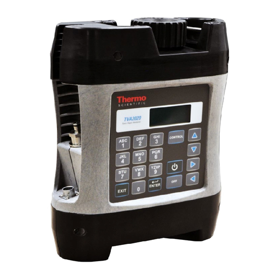
- Page 17 Chapter 1 Introduction The Thermo Scientific™ TVA2020 Toxic Vapor Analyzer, is an advanced- design, portable, organic/inorganic vapor monitor for the gas survey industry. The analyzer uses either a flame ionization detector (FID), or both an FID and a photoionization detector (PID).
-
Page 18: Chapter 1 Introduction
As a general rule of thumb, greater than 16% oxygen is required to support the flame. If underground gases or samples in gas bags are to be measured by an FID, it is advised that a dilutor be used to combat the problem. TVA2020 Instruction Manual Thermo Fisher Scientific... -
Page 19: Benefits Of Flame Ionization Detection
Ionization Detection Wide dynamic and linear range ● High sensitivity to hydrocarbon vapors (including methane) ● Very stable and repeatable response ● Virtually unaffected by ambient levels of CO, CO , and water vapor ● Thermo Fisher Scientific TVA2020 Instruction Manual... -
Page 20: Photoionization Detection
(its ionization potential). If the lamp energy is greater than the compound’s ionization potential, the PID will detect it. The lamp in the TVA2020 is 10.6 eV. Because of its smaller dynamic range (0-2000 ppm), the PID is not the detector of choice for measuring high concentrations of vapors. -
Page 21: Benefits Of Photoionization Detection
High sensitivity to aromatics, unsaturated hydrocarbons and ● Detection chlorinated hydrocarbons Ability to measure some inorganic gases ● Very simple operation ● No support gases required ● Non-destructive detector allows sample to be recovered ● Thermo Fisher Scientific TVA2020 Instruction Manual... -
Page 22: Dual Detectors
FIDs cannot detect. A high PID reading with no FID reading might suggest the presence of an inorganic compound. With readings from both detectors readily available, the TVA2020 can help a user make decisions about the type of compound present and which detector reading to use. -
Page 23: Benefits Of Dual Detectors
VENT AIR SAMPL E OUT COLLECTOR HYDROGEN SUPPLY AIR SAMPLE IN AIR SAMPLE IN ELECTRODE Figure 1–3. TVA2020 Dual Detector Configuration Benefits of Dual Benefits of Dual Detectors: Detectors Cost-effective packaging ● Detector response ratios can help characterize compounds ●... -
Page 24: Concentration Calculation And Calibration
SPECIFIC GAS CONCENT RAT ION IS BACKGROUN D C ORRECTED (IF ENABLED) INSTRUMENT RESPONSE FACTOR AND BACKGROUND CORRECTED C ONCENTRA- T ION IS RF CORRECTED USING THE CURRENT ROUTE ENTR Y RF (IF ANY) FINAL CONC ENTR ATION READING TVA2020 Instruction Manual Thermo Fisher Scientific... -
Page 25: Standard Specifications
Introduction Standard Specifications Standard Table 1–1 lists the standard specifications for the TVA2020. Specifications Table 1–1. TVA2020 Product Specifications Item Description Accuracy PID Instrument—±20 % of reading or ±0.5 ppm, whichever is greater, from 0.5 to 2,000 ppm. Accuracy listed is achieved... - Page 26 FID and PID compartments and special flow restrictors for calibrating the pump flow. mass Approximate Analyzer: FID only—9.2 lb Dual—9.4 lb) Probe Assembly: Standard Probe—0.5 lb Enhanced Probe—1.5 1-10 TVA2020 Instruction Manual Thermo Fisher Scientific...
-
Page 27: External Influences
This product is intended for use in indoor and outdoor environments as a portable instrument carried by a user, as specified in Table 1–2. The same Influences environmental conditions also apply to the sample stream being monitored. Table 1–2. TVA2020 External Influences External Influences Reference Operating Normal Operating Operative Limits Transportation and... -
Page 28: Product Safety Specifications
Introduction Product Safety Specifications Product Safety Table 1–3 lists the specifications for the TVA2020. Refer to Figure 1–4 Interconnection Control Drawing. Specifications Table 1–3. TVA2020 Product Safety Specifications Testing Laboratory, Types of Protection, Conditions of Classification and Area Classification FM: intrinsically safe for Class I, Division 1,... - Page 29 (configuration) parameters. This unit is shipped with the battery installed. The unit is ready for operation upon completion of setup, calibration, and charging. Thermo Fisher Scientific TVA2020 Instruction Manual...
-
Page 30: Chapter 2 Hardware And Startup
Hardware and Startup Overview Figure 2–1. Instrument Sidepack Display TVA2020 Instruction Manual Thermo Fisher Scientific... -
Page 31: Instrument Functions
SETUP mode as well as instrument serial number, Bluetooth friendly name, battery status, GPS coordinates, etc. In MEMORY mode, you can download data stored within the TVA2020 to a PC for analysis and printing, upload route list, calibration, and configuration parameters from a PC to the TVA2020, clear data memory, and update instrument firmware. -
Page 32: Using The Instrument
PID compartment open or FID detector cap removed. ▲ To place the TVA2020 in Startup mode, press and hold the ON key for 2 seconds until you hear a beep. The instrument will display a Please Wait Startup message, shortly after, the MAIN MENU screen is displayed. -
Page 33: Figure 2-2. Tva2020 Instrument Connections
Electrical Connection Charger Connection Figure 2–2. TVA2020 Instrument Connections WARNING Charger and USB connections are not allowed in an area classified as hazardous due to presence of flammable gases or vapors. ▲ WARNING To prevent a potential explosion, do not operate the instrument with the PID compartment open or FID detector cap removed. -
Page 34: Instrument Sidepack Display
The normal Run Display consists of the live measurement data in Lines ● 1 and 2 and menu items on lines 3 and 4. PID: 450ppm FID: 500ppm BLD___________________ Press char key Other display information appears as you page through various menus. TVA2020 Instruction Manual Thermo Fisher Scientific... -
Page 35: Instrument Sidepack Keypad
Note To turn the instrument ON, press and hold the on ON key until the speaker sounds and display flashes. ▲ Note To activate OFF, CONTROL, EXIT, and ENTER functions, press and HOLD the key for approximately 1/2 second. ▲ Thermo Fisher Scientific TVA2020 Instruction Manual... -
Page 36: Table 2-1. Keys And Functions
3 = third letter, and 0 = number. Press the appropriate key to execute the selection. Three uses: Select menu options Enter numbers, 0-9, using single keystroke Enter alphanumeric data, A-Z, 0-9, SPACE, using 2 keystrokes per character TVA2020 Instruction Manual Thermo Fisher Scientific... -
Page 37: Control Menu
PID is off, dashes will appear instead of a reading, and all PID alarms are overridden. Selecting Option 5 toggles the next screen, if Bluetooth or GPS are installed. If neither is installed, option 5 does not display. Thermo Fisher Scientific TVA2020 Instruction Manual... -
Page 38: Quick Start Procedure
7. Press 2 = Setup. 8. Press 1 = Calibrate. 9. Press 6 = Configure. 10. Press 2 = Span Concentration. 11. Enter Span Concentration for calibration gas being used and press ENTER to accept. 2-10 TVA2020 Instruction Manual Thermo Fisher Scientific... - Page 39 23. Press 2 = Span. 24. Press 3 = FID. 25. Press ENTER = Start. 26. Challenge analyzer with methane span gas and wait for readings to stabilize. 27. Press ENTER = Accept. Thermo Fisher Scientific TVA2020 Instruction Manual 2-11...
- Page 40 Note To perform more sophisticated operations, you will need to read the rest of the manual. ▲ To power down this instrument, simply press the OFF key. You must also unscrew the hydrogen tank to avoid depleting the tank supply. 2-12 TVA2020 Instruction Manual Thermo Fisher Scientific...
-
Page 41: Chapter 3 Display Menus
“Memory” on page 3-30 ● Main Menu The display on the TVA2020 analyzer is a menu-driven device. The various menus prompt you to select or enter information. With various key strokes, Structure you can accomplish all necessary setup (configuration) and operational tasks. -
Page 42: Table 3-1. Main Menu Selection And Functions
Display Menus Main Menu Structure Whenever you turn on the TVA2020, a power-up self test is performed and warning screens are displayed if any errors are found. Please refer to “Warning Messages” on page 6-6. If errors are detected, use the EXIT key to clear error message, then MAIN MENU is displayed. -
Page 43: Figure 3-1. Tva2020 Menu Structure
Once you are familiar with the various menus and know where to enter specific information, you may want to use a short cut method of tracking the menu structure. The following figure shows the complete menu structure for the TVA2020 Analyzer. SETUP INFO MEMORY 1. -
Page 44: Run Mode
(See “Bluetooth Communications” in the Options section for more information.) The TVA2020 performs accurately only after it has been properly set up (configured). The RUN mode displays (as governed by the LOG Selection) are:... -
Page 45: Accessing The Run Menu
Menu Run: Log None Whenever the TVA2020 is in the RUN mode with Log None as the logging selection, the instrument operates as a survey tool only. The readings on the probe display and instrument display show the live reading for the samples at that time. -
Page 46: Run: Log Voc
EXIT key is pressed, or the log memory is full. Run: Log VOC Whenever the TVA2020 is in the RUN mode with Log VOC as the logging selection, the instrument operates as a manual survey tool that logs its readings into memory whenever you initiate logging. - Page 47 The screen displays live readings and the tag name but no logging takes place until you either enter the logging mode from the enhanced probe or press the ENTER key again on the instrument. PID/FID FID: 24950ppm PID: 1.1ppm FID: 2.49% Enter=Start log Enter=Start log Thermo Fisher Scientific TVA2020 Instruction Manual...
-
Page 48: Run: Log F.e
The operation of the Log F.E. mode is menu driven from the hand-held probe display and requires the use of the optional TVA2020 Enhanced Probe. Whenever the TVA2020 is in the RUN mode with Log F.E. as the logging selection, the instrument logs its readings based on a pre- configured route file. -
Page 49: Setup Menu
4. At the end of the monitoring route, copy the logged readings to the personal computer. Setup Menu The Setup Menu (configuration) of the TVA2020 is the most important step in obtaining accurate gas measurements. The Setup Menu contains configuration procedures and menu structure for performing calibrations, entering ID numbers, setting alarm levels, selecting log modes, entering response multipliers and setting time/date. -
Page 50: Alarm Levels
5. Calibrate the flow sensor 6. Configure a. Calibrate the reference point(s) using known span gases. The TVA2020 can be configured for as many as nine different span gas values (2=Span). Alarm Levels The TVA2020 is supplied with three user-configurable alarms — STEL (short term exposure limit), Low Ceiling, and High Ceiling. -
Page 51: Table 3-2. Alarm Configurations
High ceiling FID: 2180ppm H alarm exceeded! Exit=Clr Press char key Note To display and change the alarm menus, the instrument must be ON but does not have to be warmed up. ▲ Thermo Fisher Scientific TVA2020 Instruction Manual 3-11... -
Page 52: Accessing The Alarm Menu
3. Press ENTER to store new values into instrument memory. 4. Press EXIT to return to the ALARM LEVELS without making a change. 3-12 TVA2020 Instruction Manual Thermo Fisher Scientific... -
Page 53: Low Ceiling Alarm
3. Press ENTER to store the new values into instrument memory. 4. Press EXIT to return to the ALARM LEVELS without making a change. Thermo Fisher Scientific TVA2020 Instruction Manual 3-13... -
Page 54: High Ceiling Alarm
3. Press ENTER to store the new values into instrument memory. 4. Press EXIT to return to the ALARM LEVELS display without making a change. Note The high ceiling alarm cannot be set higher then 30,000 ppm or ▲ 3-14 TVA2020 Instruction Manual Thermo Fisher Scientific... -
Page 55: Log Methods
ENTER on the instrument. Each F.E. log must be done individually and manually. 4. Custom The Custom mode allows the user to configure all the logging parameters. Refer to the Log Custom section for a more complete description. Thermo Fisher Scientific TVA2020 Instruction Manual 3-15... -
Page 56: Accessing The Log Menu
The previous log selection is displayed on the second line. Follow the procedure below to set the log mode. Log None From the LOG MODE menu, press 1=None to display this message briefly. The screen then returns to the SETUP MENU. 3-16 TVA2020 Instruction Manual Thermo Fisher Scientific... -
Page 57: Log Auto
In the LOG Auto mode, data is logged in the format described below: Every time logging is initiated in the Run mode, a new header is ● created. Data is logged periodically, at the user-entered log rate, in the following ● format: Thermo Fisher Scientific TVA2020 Instruction Manual 3-17... -
Page 58: Log Voc
3. Press the Up/Dn arrow keys to choose the type of sampling to be used (Max, Avg, Smp). a. Max=the maximum reading obtained during the log interval. b. Avg=the average reading obtained during the log interval. 3-18 TVA2020 Instruction Manual Thermo Fisher Scientific... -
Page 59: Log F.e
Data is logged in the following format whenever you press the LOG ● button: Approximately 4500 data samples may be taken. ● Log F.E. Use the following procedure to access the F.E. Log. Note The F.E. method requires use of the enhanced probe. ▲ Thermo Fisher Scientific TVA2020 Instruction Manual 3-19... - Page 60 2 seconds or greater than 30 seconds is selected, a warning message will appear and you will be required to re-enter the Sample Time. ▲ Note If dual option, the user must use the enhanced probe to change detector type. ▲ 3-20 TVA2020 Instruction Manual Thermo Fisher Scientific...
-
Page 61: Log Custom
Custom logging to create your own log type. The TVA2020 will prompt you through a series of questions which will assist you in setting the various logging options. - Page 62 This setting determines whether the logging should follow a pre-loaded route list of tags. If you wish to upload a list of tags to the TVA2020 and follow that list while logging, choose ON. If you do not wish to use routing, choose OFF.
-
Page 63: Passcode Protection
Display Menus Passcode Protection Passcode The TVA2020 Setup Menu can be passcode protected. This option allows you to protect the setup parameters from anyone who is not familiar with Protection your 6-digit passcode. If this feature is enabled, you need to enter your passcode each time you choose to display the SETUP menu. -
Page 64: Disable
Note To set the User ID number, the instrument must be ON but does not have to be warmed up. ▲ 1. From the MAIN MENU display, press 2=Setup. 2. From the SETUP MENU display, press 5=Other. 3. From the OTHER SETTINGS menu, press 1=User ID. 3-24 TVA2020 Instruction Manual Thermo Fisher Scientific... -
Page 65: Date
Date entries earlier than Jan. 1, 1980 or later than 2037 are invalid. ▲ 1. From the MAIN menu display, press 2=Setup. 2. From the SETUP menu display, press 5=Other. 3. From the OTHER SETTINGS menu, press 2=Date. Thermo Fisher Scientific TVA2020 Instruction Manual 3-25... -
Page 66: Time Of Day
The date must be within the valid range of 1980 to 2037. ▲ 1. From the MAIN MENU display, press 2=Setup. 2. From the SETUP MENU display, press 5=Other. 3. From the OTHER SETTINGS menu, press 3=Time. 3-26 TVA2020 Instruction Manual Thermo Fisher Scientific... -
Page 67: User Options
1. From the MAIN MENU display, press 2-Setup. 2. From the SETUP MENU display, press 5=Other. 3. From the OTHER MENU display, press 4=User Options. USER OPTIONS 1=Key Click 2=Display Delay Thermo Fisher Scientific TVA2020 Instruction Manual 3-27... -
Page 68: Key Click
Note To select the display delay, the instrument must be ON but does not have to be warmed up. ▲ 1. From the MAIN MENU display, press 2=Setup. 2. From the SETUP MENU display, press 5=Other. 3-28 TVA2020 Instruction Manual Thermo Fisher Scientific... -
Page 69: Information Menu
Ver: Current Software Version No. ● Optional Bluetooth status ● Optional GPS status ● PID zero calibration: Date and time of last calibration ● FID zero calibration: Date and time of last calibration ● Thermo Fisher Scientific TVA2020 Instruction Manual 3-29... -
Page 70: Memory
SETUP. Press EXIT to return to MAIN menu. ▲ Memory This menu allows you to link the TVA2020 to a personal computer (PC) through the USB port to copy files from and into the instrument, clear data memory, and update instrument firmware. - Page 71 Incorrect USB cable detected Exit=Clr When first connected to a PC the TVA2020 will send the correct driver files to the computer. Administrator privileges may be needed to allow the proper files to be transferred to the PC. Once connection has been established the files listed below will be displayed in a newly opened TVA2020 window.
- Page 72 CONFIG.TXT (TVA2020 Configuration) c. CAL.TXT (TVA2020 Calibration Parameters) d. FACTORY.TXT (TVA2020 Factory Calibration) Note TVA2020 only recognizes the above naming format, otherwise the file will be deleted. ▲ Upon exiting the USB MODE screen, any files that have changed will be loaded into the instrument memory.
- Page 73 Memory Choosing 2 = Clear Logging Memory will erase any loaded logged data stored in TVA2020 memory. A warning that “You are about to clear all memory” will appear and must be acknowledged before the TVA2020 will clear its memory. Be absolutely sure that you wish to clear memory before choosing this action.
- Page 74 Depending on your computer configuration, you may need to cancel one or two other message windows before this window appears. 8. Drag and Drop or Copy and Paste the new firmware file into this ‘Removable Disk’ window. 3-34 TVA2020 Instruction Manual Thermo Fisher Scientific...
- Page 75 If the problem persists after several attempts, contact the Thermo Fisher Scientific Service Department. 12. Confirm that the calibrations (gas and flow) are still valid. If needed, they can be transferred back into the instrument using the Memory/USB Mode functions. Thermo Fisher Scientific TVA2020 Instruction Manual 3-35...
-
Page 77: Chapter 4 Calibration
4-18 ● Calibration The use of multipoint calibration and multiple response factors/curves with the TVA2020 must be fully understood before employing these features. Scenarios To help explain these TVA2020 capabilities, three scenarios follow: Scenario 1 To maximize standard accuracy, it is highly recommended that you calibrate with methane for the flame ionization detector and isobutylene for the photoionization detector. -
Page 78: Scenario 3
CALIB MENU 1=Zero 2=Span 3=Backgnd 4=RF 5=Flow 6=Cfg The steps involved in calibrating the TVA2020 are as follows: 1. Configure the calibration variables (6=Cfg): Number or span points (1-9) ● Span concentration ● Background correction (None, PID, FID, Both) ●... -
Page 79: Calibration Configuration
▲ Calibration Before you calibrate the TVA2020 for the first time, you may want to customize certain calibration settings. Once you have configured these Configuration settings, you don’t need to set them again every time you calibrate unless you want to change one. -
Page 80: Number Span Pt
1=Accept Mode 2=Save mode Up/Dn=More Number Span Pt The Number Span Pt screen is used to determine the number of span points that will be used to calibrate your TVA2020. Choosing this selection will produce the following screen: PID/FID FID: PID:... - Page 81 Enter=New conc 2=PID 3=FID If the TVA2020 is configured for multiple calibration points, the span gas concentration values for Point #3 will be displayed. The Up and Down arrow keys can be used to scroll through the span gas concentration values...
-
Page 82: Background Correct
Press ENTER to accept this value and store it in the TVA’s memory. 3. If your TVA2020 is a dual detector analyzer, you may repeat the procedure for the second detector. If your TVA2020 is configured for more than one span point, you may use the Up/Dn arrow keys to select the next span point and repeat the procedure. -
Page 83: Defining The Background Correction
Press 1=Update to read live values of ambient air. PID/FID Please wait... Please wait... Sampling backgnd Sampling backgnd Enter=Accept Enter=Accept PID/FID FID: 0.3ppm PID: 0.2ppm FID: 0.3ppm Sampling backgnd Sampling backgnd Enter=Accept Enter=Accept Press ENTER. Thermo Fisher Scientific TVA2020 Instruction Manual... -
Page 84: Rf Calc Mode
The second line of the display shows what option is currently selected. If “Factor” is chosen, the TVA2020 will use a single constant response factor which is multiplied by the reading. If “Curve” is chosen, the TVA2020 will use a two constant equation. For more information, refer to the section of the manual on “Response Factors.”... -
Page 85: Cal Save Mode
Cal Save Mode This selection allows you to choose whether or not the TVA2020 will automatically save an accepted calibration. Choosing this selection from the CAL CONFIG MENU produces the following display:... -
Page 86: Defining The Response Factor
1000-2000 10-35 counts/ppm Isobutylene Example: A TVA2020 FID is calibrated with zero air and a 100 ppm Methane in air span gas. The counts observed for the zero are 2895 and the counts observed for the span are 27395. The span sensitivity is thus 245 counts/ppm [(27395-2750)/100 ppm]. -
Page 87: Response Factor Multiplier
Methane, then the FID response factor would be 2.00 (100/50). When using a response factor multiplier to correct a TVA2020 reading, the analyzer multiplies the reading by the response factor and displays the corrected reading. As in the example give above, if a 50 ppm reading is obtained by the TVA2020, the analyzer would automatically multiply 50 times 2.00 to get the actual concentration of 100 ppm. - Page 88 Up/Dn=Next RF 1=Change Enter=Accept If you would like to activate a different response factor, press ENTER=Accept. The TVA2020 will show an ACCEPTED message. If you would like to modify the response factor name or numbers, press 1=Change: PID/FID RF3: PROPANE...
- Page 89 Use the keypad to enter a new response factor and press ENTER to store it in instrument memory. Note The TVA2020 will not accept a response factor of 00.00. ▲ Note If a response curve is used, the TVA2020 will prompt you to enter two numbers. ▲ PID/FID...
-
Page 90: Zero Reference Point Calibration
Point Calibration 1. From the CALIB MENU display, press 1=Zero. Note The following sequence shows the procedure when the TVA2020 is configured with both Cal Accept mode and Cal Save mode = Auto. If either mode is Manual, an extra confirmation is required at the appropriate step. - Page 91 3. Apply the zero gas to the probe at ambient pressure (using a clean and labeled gas sampling bag) and then press ENTER. PID/FID FID: 3500 PID: 1350 FID: 3500 Wait for zero... Wait for zero... Exit=Cancel Exit=Cancel The instrument analyzes the zero sample. Thermo Fisher Scientific TVA2020 Instruction Manual 4-15...
-
Page 92: Span Reference Point(S)
The procedure is: 1. From the CALIB MENU display, press 2=Span. Note The following sequence shows the procedure when the TVA2020 is configured with both Cal mode and Cal Save mode = Auto. If either mode is Manual, an extra confirmation is required at the appropriate step. - Page 93 Exit=Cancel The instrument analyzes the span sample. When only one reference span gas concentration is used, the ACCEPTED message appears for a short time and is then replaced by the normal CALIBRATION menu. Thermo Fisher Scientific TVA2020 Instruction Manual 4-17...
-
Page 94: Flow Calibration
6. Press “2” for the second flow calibration point. 7. Adjust the pump power with the up and down arrows for a reading of 1 ±.01 LPM at the probe inlet. 4-18 TVA2020 Instruction Manual Thermo Fisher Scientific... - Page 95 Note The flow calibration values are stored in a file called FACTORY.TXT. This file can be saved to a computer and reloaded to the instrument if the flow calibration were to become corrupted. See the section on flash file transfers. ▲ Thermo Fisher Scientific TVA2020 Instruction Manual 4-19...
-
Page 97: Chapter 5 Preventive Maintenance
Cavities” on page 5-10 ● “Replacing Water Trap Probe Filter and O-Rings” on page 5-11 ● “Cleaning or Replacing a Sintered Metal Filter Cup” on page 5-13 ● “Replacing the Charcoal Filter” on page 5-14 ● Thermo Fisher Scientific TVA2020 Instruction Manual... -
Page 98: Preventive Maintenance
However, misusing or mishandling the battery packs can and Precautions lead to fluid leakage, heat generation, fire or an explosion. WARNING Misusing or mishandling the battery packs can lead to fluid leakage, heat generation, fire or an explosion. ▲ TVA2020 Instruction Manual Thermo Fisher Scientific... - Page 99 Do not assemble or modify the battery packs or the lithium-ion ● batteries located inside the battery packs. Do not install the battery packs into to the TVA2020 if the battery ● packs leak electrolyte, change color, change shape, or become deformed in any other way.
-
Page 100: Safety Test Criteria
Do not leave the battery on charge for extended periods (greater than 96 hours). If you wish to remove the battery from the TVA2020 for charging or swapping with a spare battery, turn the instrument off. Safety Test Criteria The lithium-ion battery packs are designed to meet all U.S. -
Page 101: Precautions In Handling And Storage
Follow all regulatory safety and labeling precautions when shipping ● hydrogen in the TVA2020. Note A bleeder assembly is provided in the tool kit to allow the hydrogen tank to be emptied for common carrier shipment. To use the bleeder, manually screw the bleeder onto the tank valve and allow the hydrogen to vent. -
Page 102: Fuel Refilling Procedure
— do not overtighten.) 4. Open supply tank valve. Move fill adapter valve to FILL position. 5. Wait for TVA2020 tank to fill. This may take 2 to 3 minutes because of flow restrictors in the tank and fill adapter. -
Page 103: Cleaning An Fid Cartridge
(Figure 5–2). 4. Remove the cartridge by pulling on the extractor. Unscrew the extractor from the cartridge. Clean or replace the cartridge. 5. To insert a new cartridge, reverse the procedure. Thermo Fisher Scientific TVA2020 Instruction Manual... -
Page 104: Figure 5-2. Removing The Fid Cartridge
45 °C to 55 °C for one hour. When dry, re- insert the cartridge into the instrument, reversing the removal procedure. Do not overtighten cap. CAUTION Do not allow any contact with the igniter coil during cleaning. ▲ TVA2020 Instruction Manual Thermo Fisher Scientific... -
Page 105: Cleaning The Fid Detector Cap
3. Clean the cap using the isopropyl alcohol followed with a de-ionized or distilled water rinse. Blow out carefully with compressed dry air. 4. Replace the cap. Figure 5–3. Cleaning the FID Detector Cap Thermo Fisher Scientific TVA2020 Instruction Manual... -
Page 106: Cleaning The Fid Detector Cavities
6. Dry the inside of the cavity using a low heat gun. 7. Insert the cartridges into their respective cavities by reversing the procedure. Note that the cartridges must be rotated to properly locate the key tabs. 5-10 TVA2020 Instruction Manual Thermo Fisher Scientific... -
Page 107: Replacing Water Trap Probe Filter And O-Rings
4. Filter can be inserted in either direction into top housing. 5. Screw bottom housing into top housing. Probe Nut Nozzle O-ring Water Trap O-ring Nozzle Base Figure 5–4. Water Trap Probe Assembly – Filter and O-Ring Replacing Thermo Fisher Scientific TVA2020 Instruction Manual 5-11... -
Page 108: Replacing The O-Rings
5. Repeat for other housing if necessary. 6. Place filter into top housing. 7. Screw bottom housing into top housing. Nozzle O-ring Water trap O-ring Nozzle Base Figure 5–5. Water Trap Probe Assembly – Filter and O-Ring Replacing 5-12 TVA2020 Instruction Manual Thermo Fisher Scientific... -
Page 109: Cleaning Or Replacing A Sintered Metal Filter Cup
40 °C to 55 °C for one hour. You can then re-insert the filter into the sampling assembly and screw in the cap. Filter Holder O-ring Spring Filter Cup O-ring Sample Inlet O-ring Figure 5–6. Sintered Metal Filter – Cleaning or Replacing Thermo Fisher Scientific TVA2020 Instruction Manual 5-13... -
Page 110: Replacing The Charcoal Filter
8. Re-insert the sampling assembly into the probe and tighten the probe nut. THREAD ED EN D WITH CARTRIDGE TEFLON FILLED WITH TAPE ACT IVATED CH ARCOAL Figure 5–7. Activated Charcoal Filter Adapter 5-14 TVA2020 Instruction Manual Thermo Fisher Scientific... - Page 111 Chapter 6 Troubleshooting This chapter provides the following troubleshooting and service support information: “Troubleshooting Guide” on page ● “Warning Messages” on page ● “Service Locations” on page ● Thermo Fisher Scientific TVA2020 Instruction Manual...
-
Page 112: Chapter 6 Troubleshooting
Service pump. Insufficient hydrogen supply Check hydrogen gauge on (<500 psi) supply tank. Refill tank if necessary. Hydrogen leak Check low pressure hydrogen output gauge. If <8 psi, call Thermo Fisher Scientific Service Department. TVA2020 Instruction Manual Thermo Fisher Scientific... - Page 113 Flameout problems Sample hydrogen content too Use dilutor kit to achieve high concentration within the dynamic range. Insufficient oxygen in the Use dilutor kit to dilute sample (<14%) sample with air contaminating sufficient oxygen. Thermo Fisher Scientific TVA2020 Instruction Manual...
- Page 114 Clean PID window. contaminated or faulty Replace PID capsule. Internal detector fault or Call Thermo Fisher Scientific contamination Service Department. Slow response time Insufficient sample flow Clean/replace filter cups. Clean/replace flame arrestor. Clean/replace sample line. TVA2020 Instruction Manual Thermo Fisher Scientific...
- Page 115 High background readings High ambient concentration N/A. Zero drift/improper Ensure proper zero/span calibration calibration. Sample line contamination Clean/replace sample line. Clean/replace filter cups. Detector capsule Clean/replace FID capsule. contamination Clean PID window. Replace PID capsule. Thermo Fisher Scientific TVA2020 Instruction Manual...
-
Page 116: Warning Messages
Troubleshooting Warning Messages Warning The following is a list of error and warning messages for the TVA2020. Messages Table 6–2. Warning Messages Message Description Battery Power is low. This display occurs whenever the battery has reached a low level (approximately 6.5 V). It indicates that approximately 15 minutes of operating time remain. -
Page 117: Service Locations
Service is available from exclusive distributors worldwide. Contact one of the phone numbers below for product support and technical information Locations or visit us on the web at www.thermoscientific.com/aqi. 1-866-282-0430 Toll Free 1-508-520-0430 International Thermo Fisher Scientific TVA2020 Instruction Manual... -
Page 119: Chapter 7 Servicing
From time to time, you must remove and renew several components of the TVA2020 analyzer. Some components may be replaced as normal maintenance functions performed by operating personnel. Other components, however, should be replaced only by personnel thoroughly trained and familiar with the analyzer instrument and its applications. -
Page 120: Replacement Parts List
Servicing Replacement Parts List Replacement Table 7–1 lists the replacement parts for the TVA2020 major subassemblies. Refer to Figure 7–1 to identify the component location. Parts List Table 7–1. TVA2020 Replacement Parts Part Number Description 56-011811 Battery Pack 114012-00 Hydrogen Tank... - Page 121 Service Plans are available; contact Thermo Fisher Scientific Department for further information.) ▲ WARNING Never change an electrical component in an area classified as hazardous due to presence of flammable gases or vapors. ▲ Thermo Fisher Scientific TVA2020 Instruction Manual...
-
Page 122: Figure 7-1. Tva2020 Component Layout
Assy Battery Internal Housing Frame Bluetooth Antenna Sample Inlet Connector Instrument Probe Cable Assy PID Assy Charger Cable Assy Sample Pump Strap Holder (2) FID Assy Connector Housing Cover Figure 7–1. TVA2020 Component Layout TVA2020 Instruction Manual Thermo Fisher Scientific... -
Page 123: Opening The Instrument
3. Position the instrument resting on its back with the keypad facing up. 4. Grasp the instrument cover near the probe connections and carefully open the cover to the right. Thermo Fisher Scientific TVA2020 Instruction Manual... -
Page 124: Replacing The Battery
Install the tank in the instrument by inserting it into the receptacle on the top and tightening (left hand threads tighten counterclockwise) until the rubber tank boot is flush with the instrument sidepack and a slight resistance is felt. Do not overtighten. TVA2020 Instruction Manual Thermo Fisher Scientific... -
Page 125: Precautions In Handling And Storage
Follow all regulatory safety and labeling precautions when shipping ● hydrogen in the TVA2020. Note A bleeder assembly is provided in the tool kit to allow the hydrogen tank to be emptied for common carrier shipment. To use the bleeder, manually screw the bleeder onto the tank valve and allow the hydrogen to vent. - Page 126 — do not overtighten.) 4. Open supply tank valve. Move fill adapter valve to FILL position. 5. Wait for TVA2020 tank to fill. This may take 2 to 3 minutes because of flow restrictors in the tank and fill adapter.
-
Page 127: Cleaning The Pid Lamp
2. Remove the filter cap by applying slight upward pressure with the tip of a screwdriver or X-Acto blade just below the hole in the cap and between the cap and housing; it will pop off (Figure 7–4). Thermo Fisher Scientific TVA2020 Instruction Manual... -
Page 128: Figure 7-4. Removing The Filter Cap
4. Using the X-Acto blade, remove the spacer and set aside (Figure 7–6). Figure 7–6. Removing the Spacer 5. With fine tipped tweezers, carefully remove the cell assembly by prying under the cell’s edge where connector pins are located (Figure 7–7). 7-10 TVA2020 Instruction Manual Thermo Fisher Scientific... -
Page 129: Figure 7-7. Removing The Cell Assembly
Another indication of cleaning completeness is that you have used about 1/6-inch of the pads surface during the procedure (Figure 7–9). Figure 7–9. Cleaning the PID Lamp Thermo Fisher Scientific TVA2020 Instruction Manual 7-11... -
Page 130: Figure 7-10. Installing The Lamp Into The Sensor
Make sure the cell assembly is flush with the lamp window (Figure 7–12). Figure 7–12. Installing the Cell Assembly 7-12 TVA2020 Instruction Manual Thermo Fisher Scientific... -
Page 131: Figure 7-13. Placing The Spacer
If the cap key is incorrectly aligned, there will be a noticeable bulge on the side of the cap (Figure 7–15). Figure 7–15. Aligning the Cap Key Thermo Fisher Scientific TVA2020 Instruction Manual 7-13... -
Page 132: Replacing The Fid End Cap
7–16) to diagnose flow problems. Start with the Leak Check procedure with the probe connected to the instrument. The leak and flow check procedures can be performed on the sub assemblies to identify the source of the problem. 7-14 TVA2020 Instruction Manual Thermo Fisher Scientific... -
Page 133: Figure 7-16. Sample Flow Troubleshooting Flowchart
Servicing Flow Tests Figure 7–16. Sample Flow Troubleshooting Flowchart Thermo Fisher Scientific TVA2020 Instruction Manual 7-15... -
Page 134: Leak Check
6. Record the counts associated with the pump off. 7. From the CONTROL MENU, press 1=Pump On. 8. Plug the inlet of the probe. The counts should drop to within ±200 of the “Pump Off” recorded value. 7-16 TVA2020 Instruction Manual Thermo Fisher Scientific... -
Page 135: Flow Check
2. From the SETUP MENU, choose 1=Calib > 5=Flow. 3. Establish the 1 ±.01 LPM flow at the probe inlet. a. Typical values are 50-60% power with 28K-30K counts. 4. Press Enter=Accept to save the Flow 1 values. Thermo Fisher Scientific TVA2020 Instruction Manual 7-17... - Page 136 Note The flow calibration values are stored in a file called FACTORY.TXT. This file can be saved to a computer and reloaded to the instrument if the flow calibration were to become corrupted. See the section on flash file transfers. ▲ 7-18 TVA2020 Instruction Manual Thermo Fisher Scientific...
-
Page 137: Servicing The Pump
(Figure 7–17). Tygon Tubing Hex Elbow 8 pin Connector Figure 7–17. Removing the Pump 4. Lift the pump up and out of the instrument. 5. Disconnect the pump motor from the pump board. Thermo Fisher Scientific TVA2020 Instruction Manual 7-19... -
Page 138: Accessing The Orifice
Figure 7–18. Replacing the Pump Accessing the Use the following procedure to access the orifice. Orifice 1. Remove the hex head screw. 2. Pull the orifice block apart. 3. Remove the orifice for cleaning. 7-20 TVA2020 Instruction Manual Thermo Fisher Scientific... -
Page 139: Replacing The Pump
3. Remove the old valveplate (030) from the Compressor housing (040). 4. Repeat steps 2 and 3 for opposite pump head. 5. Place the new valveplate (030) in the contour on the compressor housing (040). Do not use tools! Thermo Fisher Scientific TVA2020 Instruction Manual 7-21... -
Page 140: Figure 7-19. Exploded View Of Pump Head
6. Install headplate (020) on to compressor housing (040) 7. Install the five new screws using a Phillips head screw driver. 8. Repeat steps 5-7 for opposite head. Figure 7–19. Exploded View of Pump Head 7-22 TVA2020 Instruction Manual Thermo Fisher Scientific... -
Page 141: Replacing The Sample Line In Enhanced Probe
9. Cut the other end of the tubing to the proper length and insert it into the end of the quick-connect fitting. (Allow 5/8-inch of tubing inside the fitting.) Thermo Fisher Scientific TVA2020 Instruction Manual 7-23... -
Page 142: Figure 7-20. Replacing Sample Line In Enhanced Probe
Servicing Replacing the Sample Line in Enhanced Probe Figure 7–20. Replacing Sample Line in Enhanced Probe 7-24 TVA2020 Instruction Manual Thermo Fisher Scientific... -
Page 143: Replacing Sample Line In Sample Probe
5. Attach the new tubing and return the water trap to either handle half. Make sure the tubing is routed correctly in the grooves. 6. Reinstall the three screws. Water Trap O-ring O-ring Tube Screws (3) Figure 7–21. Replacing the Sample Line in Simple Probe Thermo Fisher Scientific TVA2020 Instruction Manual 7-25... -
Page 144: Replacing The Connector Access Door
3. Take the new door and press the retaining tail into the hole. Use a small blade screwdriver to work the tail into the hole. Figure 7–22. Replacing the Connector Access Door 7-26 TVA2020 Instruction Manual Thermo Fisher Scientific... -
Page 145: Replacing The Internal Battery Charger Connector Cable
4. Re-use the screws to mount the new connector cable. 5. Reconnect the main power cable to the new charger cable. Battery Charger Connector from Main Power Cable Screws Figure 7–23. Replacing the Internal Battery Charger Connector Cable Thermo Fisher Scientific TVA2020 Instruction Manual 7-27... -
Page 146: Replacing The Internal Probe Connector Cable
4. Install the new probe connector cable assembly and secure in the housing. 5. Reconnect the cable to the main board. Screw Connector on Main Board Figure 7–24. Replacing the Internal Probe Connector Cable 7-28 TVA2020 Instruction Manual Thermo Fisher Scientific... -
Page 147: Figure 8-1. Sample Probe Option
Chapter 8 Optional Accessories The TVA2020 is available with the following options: “Sample Probe Option” on page ● “Enhanced Probe Option” on page ● “Telescoping Extension Option” on page 8-11 ● “Activated Charcoal Filter Adapter” on page 8-12 ● “Bluetooth Communications”... -
Page 148: Optional Accessories
Option need to access the sidepack keypad. There are three buttons on the Enhanced Probe which allow you to interact with the TVA2020: MENU – Used to cause the menu to appear on the bottom of the ● probe display and to step through the available selections SELECT –... -
Page 149: Enhanced Probe Display
> << < IGNITE> > > < < CLR MENU > > < SELECT MENU PROBE MENU DISPLAY BUTTON FOR BUT TON MENU SELECTOR DISPLAY BACKLIGHTING BUTT ON Figure 8–3. Enhanced Probe Option Display Thermo Fisher Scientific TVA2020 Instruction Manual... -
Page 150: Enhanced Probe Keys
2. The enhanced probe display will display the detector reading (FID or PID) at the top and an analog bargraph on the bottom. 0.66 Tag: 3. Press the MENU key on the Enhanced probe display to show the Opening menu: TVA2020 Instruction Manual Thermo Fisher Scientific... -
Page 151: Auto Logging With The Enhanced Probe
3. Choose “Start log sampling” to begin Auto logging. 4. The Enhanced probe will display the countdown and continue to log until EXIT is selected at the probe or the sidepack keypad. Thermo Fisher Scientific TVA2020 Instruction Manual... -
Page 152: Voc Logging With The Enhanced Probe
(Maximum, Average, or Last Reading). 0.66 Tag: 0.59ppm 2.50ppm [Sav] –Again -Exit 5. You may choose to save the reading (SAV), repeat the reading for the same tag (AGAIN), or return to the previous menu (EXIT). TVA2020 Instruction Manual Thermo Fisher Scientific... -
Page 153: Fe Logging With The Enhanced Probe
In addition to the concentration display at the top, the FE mode shows several fields which have been filled in by the downloaded route. The TVA2020 starts at the first record in the route and displays the component tag number (Tag), equipment type (Eqp), equipment size (Size), and leak definition (Leak). -
Page 154: Navigating The Route File
You can also enter a tag via the keypad and the TVA2020 will automatically skip to that tag if it is contained within the route. If the tag is not contained within the route, a “TAG NOT FOUND”... -
Page 155: Repair Menus
Repair Menus If the reading obtained during the logging interval exceeds the leak definition, the TVA2020 will indicate that it is a leak by printing “Leaker!” If you wish, you may record what part of the component is leaking and what action was taken as a first attempt at repair. -
Page 156: Additional Component Information
Additional Component Displays containing additional information about the component and the TVA2020 status are available from the handheld unit. If you press and Information hold the MENU key for approximately 2 seconds, the Enhanced display will present an INFO page: 0.66... -
Page 157: Telescoping Extension Option
Then, insert the appropriate sampling assembly into the other end of the extension unit and tighten the retaining nut. PROBE ASSEMBLY PROBE NUT CLOSE AREA SAMPLER FILTER ADAPTER TELESCOPING EXTENSION UNIT Figure 8–4. Telescoping Extension Option Thermo Fisher Scientific TVA2020 Instruction Manual 8-11... -
Page 158: Activated Charcoal Filter Adapter
Under typical industrial air monitoring conditions, the filter will last for many days of continuous sampling. For information on replacing the charcoal filter, see “Replacing the Charcoal Filter” on page 5-14. 8-12 TVA2020 Instruction Manual Thermo Fisher Scientific... -
Page 159: Bluetooth Communications
Communications Data Logging, to turn the pump on or off, or to reignite the FID. The TVA 2020 will advertise the Bluetooth friendly name TVA2020<last six hex digits of Bluetooth address>. A PC or PDA can then connect to it using a passkey of 0000. - Page 160 Note The commands are case insensitive. ▲ All commands are terminated by <CR> or <CR><LF>. If an invalid command is received by the TVA, it will respond with “bad cmd”. This response is terminated by <CR><LF>. 8-14 TVA2020 Instruction Manual Thermo Fisher Scientific...
-
Page 161: Digital Data Logging (Bluetooth)
Digital data logging is initially disabled and the logging type is set according to what detectors are installed so, e.g., if only an FID is installed the logging type will be set to FID data only logging. Thermo Fisher Scientific TVA2020 Instruction Manual 8-15... -
Page 162: Gps
Latitude (Degrees with 5 digits to the right of the decimal) ● Longitude (Degrees with 5 digits to the right of the decimal) ● Altitude (Meters) ● Resolution (Meters) ● Number of Satellites ● 8-16 TVA2020 Instruction Manual Thermo Fisher Scientific... -
Page 163: Appendix A Warranty
(i) normal wear and tear, (ii) accident, disaster or event of force majeure, (iii) misuse, fault or negligence of or by Buyer, (iv) use of the Products in a manner for which Thermo Fisher Scientific TVA2020 Instruction Manual... - Page 164 OR WRITTEN, WITH RESPECT TO THE PRODUCTS, INCLUDING WITHOUT LIMITATION ALL IMPLIED WARRANTIES OF MERCHANTABILITY OR FITNESS FOR ANY PARTICULAR PURPOSE. SELLER DOES NOT WARRANT THAT THE PRODUCTS ARE ERROR-FREE OR WILL ACCOMPLISH ANY PARTICULAR RESULT. TVA2020 Instruction Manual Thermo Fisher Scientific...
-
Page 165: Appendix B Text Data Formats
ASCII text. All files are read to and written from the root directory of the file system for the memory device. The TVA2020 generates files with both <CR> and <LF> at the end of each line. However, the TVA accepts files with <CR><LF>, just <CR>, or just <LF>. -
Page 166: Route Database
Each route entry field consists of three columns of data: the data type, field width, and title. TVA2020 Instruction Manual Thermo Fisher Scientific... - Page 167 <CR><LF> at any time (does not require 16 characters). The label must match the label previously defined in the ROUTE FIELDS section of the file. Each additional line is a pick list entry. The pick list is terminated by Thermo Fisher Scientific TVA2020 Instruction Manual...
- Page 168 <CR><LF>. Before the first entry is accepted, the instrument’s route and log memory is cleared. Partial text entries are processed as ending in trailing spaces. Partial number entries are processed as if complete. The default value for fields not included in the entry are: TVA2020 Instruction Manual Thermo Fisher Scientific...
- Page 169 1000000003 HOUSTON 2 AREA3 SUBAREA3 0 1.00 CSL 1.75 DESCRIPTION 3 1000000004 HOUSTON 2 AREA4 SUBAREA4 0 1.00 DFL 10.00 DESCRIPTION 4 1000000005 LEFT OF TRACKS AREA5 SUBAREA5 0 1.00 PKG 5.50 DESCRIPTION 5 Thermo Fisher Scientific TVA2020 Instruction Manual...
-
Page 170: Route List
Header Line 2 AREA SUBAREA LEAK RATE RESP FACT EQUIP<CR><LF> SIZE DESCRIPTION<CR><LF> The route entry format is: Byte Length Item Format text delimiter space Area text delimiter space Subarea text delimiter space Leak rate floating point TVA2020 Instruction Manual Thermo Fisher Scientific... - Page 171 SUBAREA RATE FACT TYP SIZE DESCRIPTION ---------------- -------- -------- ----- ---- --- ------ ----------- 0123 PLANT 1 SECTION2 10.3 2.00 VLV 5.125 OUTLET 0124 PLANT 1 SECTION2 100 1.00 PMP 5.125 0124 PLANT 1 SECTION2 100 1.00 0125 Thermo Fisher Scientific TVA2020 Instruction Manual...
-
Page 172: Configuration
RF1 (PID)=nnnnnnnnnn xx.xx +yy.yy<CR><LF> RF9 (PID)=nnnnnnnnnn xx.xx +yy.yy<CR><LF> RF0 (FID)=DEFAULT 1.00 0.00<CR><LF> RF1 (FID)=nnnnnnnnnn xx.xx +yy.yy<CR><LF> RF9 (FID)=nnnnnnnnnn xx.xx +yy.yy<CR><LF> <CR><LF> ALARMS<CR><LF> ------<CR><LF> STEL (PID)=ffffff PPM|% <CR><LF> LOW (PID)=ffffff PPM|% <CR><LF> HIGH (PID)=ffffff PPM|% <CR><LF> TVA2020 Instruction Manual Thermo Fisher Scientific... - Page 173 VER= 1.00 MODEL=TVA2020 SERIAL NUMBER=123456789012 DETECTOR=PID&FID OPERATOR ID=USERID LOGGING ------- LOG MODE=NONE LOG STORAGE FORMAT=NONE LOG SAMPLE TIME=0 LOG SAMPLE TIME UNIT=SEC LOG DATA STORED=SAMPLE LOG UNIT LOCK=OFF LOG AUTO REPEAT=OFF LOG SAVE MODE=MANUAL Thermo Fisher Scientific TVA2020 Instruction Manual...
- Page 174 STEL (FID)= 0.00 PPM LOW (FID)= 0.00 PPM HIGH (FID)= 0.00 PPM USER OPTIONS ------------ PROBE=ENHANCED KEY CLICK=OFF DISPLAY DELAY=MEDIUM PC LINK TYPE=TEXT-AUTO DIGITAL DATA LOGGING=PID&FID BLUETOOTH POWER=ON GPS POWER=ON POWER (PID)=ON POWER (FID)=ON B-10 TVA2020 Instruction Manual Thermo Fisher Scientific...
-
Page 175: Calibration
= minute of calibration, 00-59 ss = second of calibration, 00-59 bbbbbbbb = detector reading for calibration gas, integer, right justified, leading spaces fffffffff = count status: "OK ", no errors "DET_OFF ", detector reading invalid Thermo Fisher Scientific TVA2020 Instruction Manual B-11... - Page 176 CALIB KNOWN CALIB MEASURED TYPE CONC DATE/TIME CALIB VALUE ----- ---------- ------------------- ------------------------- ZERO 0 PPM 12 DEC 99 20:20:10 0 COUNTS OK SPAN1 10.23 PPM 12 DEC 99 20:20:30 123456 COUNTS DET_FAIL B-12 TVA2020 Instruction Manual Thermo Fisher Scientific...
-
Page 177: Factory
POINT 2 TIME =1324747069 POINT 2 FLAGS =0 POINT 2 COUNT =28642 POINT 2 DUTY =34 POINT 3 TIME =1334747227 POINT 3 FLAGS =0 POINT 3 COUNT =29690 POINT 3 DUTY =180 SLOPE =36.6918 INTERCEPT =23264 Thermo Fisher Scientific TVA2020 Instruction Manual B-13... - Page 178 Text Data Formats Factory SUM OF SQUARES=0.934123 B-14 TVA2020 Instruction Manual Thermo Fisher Scientific...
-
Page 179: Calibration History
"ZERO " "SPAN1 " "SPAN2 " "SPAN3 " "SPAN4 " "SPAN5 " "SPAN6 " "SPAN7 " "SPAN8 " "SPAN9 " "ZERO* " "SPAN1*" "SPAN2*" "SPAN3*" "SPAN4*" "SPAN5*" "SPAN6*" "SPAN7*" "SPAN8*" "SPAN9*" Thermo Fisher Scientific TVA2020 Instruction Manual B-15... - Page 180 PID SPAN1* 10.23 PPM 12 DEC 99 20:20:30 123456 COUNTS DET_FAIL FID SPAN2 50.23 PPM 12 DEC 99 20:20:40 1234567 COUNTS OK FID SPAN3 100.23 PPM 12 DEC 99 20:20:50 12345678 COUNTS OVERFLOW B-16 TVA2020 Instruction Manual Thermo Fisher Scientific...
-
Page 181: Logged Data
PID BACKGROUND PID CONCENTRATION --------- -------- -------------------- -------------------- / dd mmm yy hh:mm:ss xxxxxx uuu fffffffff xxxxxx uuu fffffffff / FID BACKGROUND FID CONCENTRATION <CR><LF> -------------------- --------------------<CR><LF> xxxxxx uuu fffffffff xxxxxx uuu fffffffff<CR><LF> Thermo Fisher Scientific TVA2020 Instruction Manual B-17... - Page 182 / FID BACKGROUND FID CONCENTRATION -------------------- -------------------- / xxxxxx uuu fffffffff xxxxxx uuu fffffffff / GPS DATA <CR><LF> ------------------------------<CR><LF> aaaaaaaaa ooooooooo hhhh rr nn<CR><LF> B-18 TVA2020 Instruction Manual Thermo Fisher Scientific...
- Page 183 = day (01-31) mmm = month: “JAN”, January “FEB”, February “MAR”, March “APR”, April “MAY”, May “JUN”, June “JUL”, July “AUG”, August “SEP”, September “OCT”, October “NOV”, November “DEC”, December yy = Year (00-99) Thermo Fisher Scientific TVA2020 Instruction Manual B-19...
- Page 184 "HIGH&STEL", high alarm and STEL, not "UNDERFLOW" "LOW&STEL ", low alarm and STEL, no high alarm, not "UNDERFLOW" ddd = detector: "PID" "FID" lllllll = leak indicator: " OK ", no leak "LEAKER!", leak B-20 TVA2020 Instruction Manual Thermo Fisher Scientific...
- Page 185 0.03 PPM OK 5.30 PPM OK 01 JAN 95 08:15:25 0501 103 PPM HIGH_ALRM 0.03 PPM OK 99.30 PPM OK 01 JAN 95 08:25:37 0502 25.67 PPM OK 0.04 PPM OK 5.30 PPM OK Thermo Fisher Scientific TVA2020 Instruction Manual B-21...
- Page 186 19 MAR 03 13:11:35 3 0.00 PPM OK 0.00 PPM DET_FAIL ALL FIXED! 19 MAR 03 13:12:20 4 0.00 PPM OK 0.00 PPM DET_FAIL 19 MAR 03 13:12:38 5 0.00 PPM OK 0.00 PPM DET_FAIL B-22 TVA2020 Instruction Manual Thermo Fisher Scientific...
-
Page 187: Appendix C Response Factors
Appendix C Response Factors The TVA2020 is a portable vapor analyzer for gas survey monitoring. Each Response unit is factory calibrated with Methane (in the case of the FID) and Factors Isobutylene (in the case of the PID). However, both detectors respond to many different compounds with differing levels of sensitivity. - Page 188 50 by 0.50 to get the actual concentration (100 ppm). Like any FID or PID, the TVA2020 will respond to many different compounds, producing a survey reading of all detectable compounds present. If a single compound is present, a response factor can be applied to correct for the response of that compound.
- Page 189 Response Factors expressed as “100 ppm of Methane” if the calibration gas used was Methane. Please note that the TVA2020 detectors can be calibrated with gases other than the factory standards as long as the detector has adequate response to that compound.
- Page 190 Response Factors Response Factors TVA2020 Instruction Manual Thermo Fisher Scientific...
Need help?
Do you have a question about the TVA2020 and is the answer not in the manual?
Questions and answers