Sign In
Upload
Manuals
Brands
Thermo Scientific Manuals
Measuring Instruments
TVA2020
User Manuals: Thermo Scientific TVA2020 Vapor Analyzer
Manuals and User Guides for Thermo Scientific TVA2020 Vapor Analyzer. We have
1
Thermo Scientific TVA2020 Vapor Analyzer manual available for free PDF download: Instruction Manual
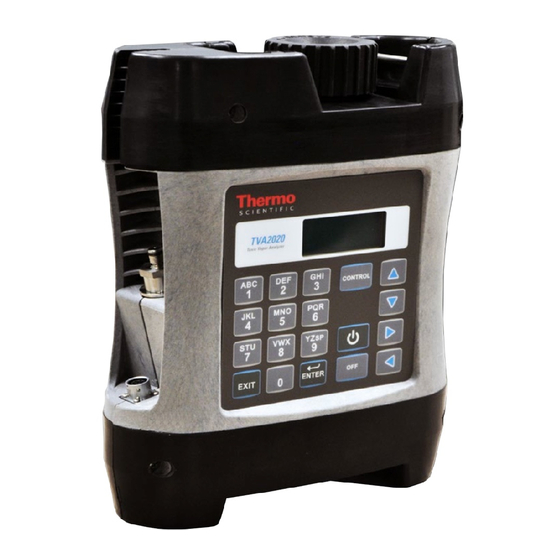
Thermo Scientific TVA2020 Instruction Manual (190 pages)
Toxic Vapor
Brand:
Thermo Scientific
| Category:
Measuring Instruments
| Size: 1 MB
Table of Contents
Weee Compliance
3
About this Manual
5
Table of Contents
9
Chapter 1 Introduction
18
Flame Ionization Detection (FID)
18
Benefits of Flame Ionization Detection
19
Figure 1-1. Typical Flame Ionization Detector
19
Photoionization Detection
20
Benefits of Photoionization Detection
21
Figure 1-2. Typical Photoionization Detector
21
Dual Detectors
22
Benefits of Dual Detectors
23
Figure 1-3. TVA2020 Dual Detector Configuration
23
Concentration Calculation and Calibration
24
Standard Specifications
25
Table 1-1. TVA2020 Product Specifications
25
External Influences
27
Table 1-2. TVA2020 External Influences
27
Product Safety Specifications
28
Figure 1-4. Interconnection Control Drawing
28
Table 1-3. TVA2020 Product Safety Specifications
28
Chapter 2 Hardware and Startup
30
Overview
30
Figure 2-1. Instrument Sidepack Display
30
Instrument Functions
31
Using the Instrument
32
Startup
32
Instrument Connections
32
Figure 2-2. TVA2020 Instrument Connections
33
Instrument Sidepack Display
34
Instrument Sidepack Keypad
35
Figure 2-3. Keypad
35
Table 2-1. Keys and Functions
36
Control Menu
37
Quick Start Procedure
38
Chapter 3 Display Menus
41
Main Menu Structure
41
Table 3-1. Main Menu Selection and Functions
42
Figure 3-1. TVA2020 Menu Structure
43
Run Mode
44
Accessing the Run Menu
45
Run: Log None
45
Run: Log Auto
45
Run: Log VOC
46
Run: Log F.E
48
Setup Menu
49
Calibration Settings
49
Alarm Levels
50
Table 3-2. Alarm Configurations
51
Accessing the Alarm Menu
52
STEL Level Alarm
52
Low Ceiling Alarm
53
High Ceiling Alarm
54
Log Methods
55
Table 3-3. Available Log Data Types
55
Accessing the LOG Menu
56
Log None
56
Log Auto
57
Log VOC
58
Log F.E
59
Log Custom
61
Passcode Protection
63
New Passcode
63
Enable
63
Disable
64
Other Settings
64
User Identification Number
64
Date
65
Time of Day
66
User Options
67
Key Click
68
Display Delay
68
Information Menu
69
Memory
70
Chapter 4 Calibration
77
Calibration Scenarios
77
Scenario 1
77
Scenario 2
77
Scenario 3
78
Calibration Configuration
79
Number Span Pt
80
Defining the Span Gas Concentration(S)
80
Background Correct
82
Table 4-1. Gas Concentration Units
82
Defining the Background Correction
83
RF Calc Mode
84
Cal Accept Mode
84
Cal Save Mode
85
Detector Counts
85
Defining the Response Factor
86
Table 4-2. Detector Counts
86
Response Factor Multiplier
87
Response Curve
87
Zero Reference Point Calibration
90
Span Reference Point(S)
92
Flow Calibration
94
Chapter 5 Preventive Maintenance
97
Preventive Maintenance
98
Safety Precautions
98
Replacement Parts
98
Battery and Battery Charger
98
Battery Warnings and Precautions
98
Safety Test Criteria
100
Hydrogen Gas Tank
100
Precautions in Handling and Storage
101
Fuel Refilling Procedure
102
Cleaning an FID Cartridge
103
Figure 5-1. Replacing the FID Cartridge
103
Figure 5-2. Removing the FID Cartridge
104
Cleaning the FID Detector Cap
105
Figure 5-3. Cleaning the FID Detector Cap
105
Cleaning the FID Detector Cavities
106
Replacing Water Trap Probe Filter and O-Rings
107
Figure 5-4. Water Trap Probe Assembly - Filter and O-Ring Replacing
107
Replacing the O-Rings
108
Figure 5-5. Water Trap Probe Assembly - Filter and O-Ring Replacing
108
Cleaning or Replacing a Sintered Metal Filter Cup
109
Figure 5-6. Sintered Metal Filter - Cleaning or Replacing
109
Replacing the Charcoal Filter
110
Figure 5-7. Activated Charcoal Filter Adapter
110
Chapter 6 Troubleshooting
112
Troubleshooting Guide
112
Table 6-1. Troubleshooting
112
Warning Messages
116
Table 6-2. Warning Messages
116
Service Locations
117
Chapter 7 Servicing
119
Replacement Parts List
120
Table 7-1. TVA2020 Replacement Parts
120
Figure 7-1. TVA2020 Component Layout
122
Opening the Instrument
123
Figure 7-2. Hardware
123
Replacing the Battery
124
Hydrogen Gas Tank
124
Precautions in Handling and Storage
125
Fuel Refilling Procedure
125
Cleaning the PID Lamp
127
Figure 7-3. Removing the PID Sensor
127
Figure 7-4. Removing the Filter Cap
128
Figure 7-5. Removing the Filter Media
128
Figure 7-6. Removing the Spacer
128
Figure 7-7. Removing the Cell Assembly
129
Figure 7-8. Removing the PID Lamp
129
Figure 7-9. Cleaning the PID Lamp
129
Figure 7-10. Installing the Lamp into the Sensor
130
Figure 7-11. Pressing down the PID Lamp
130
Figure 7-12. Installing the Cell Assembly
130
Figure 7-13. Placing the Spacer
131
Figure 7-14. Placing the Filter Media
131
Figure 7-15. Aligning the Cap Key
131
Replacing the FID End Cap
132
Flow Tests
132
Figure 7-16. Sample Flow Troubleshooting Flowchart
133
Leak Check
134
Flow Check
135
Flow Calibration
135
Servicing the Pump
137
Removing the Pump Assembly
137
Figure 7-17. Removing the Pump
137
Accessing the Orifice
138
Figure 7–18. Replacing the Pump
138
Replacing the Pump
139
Replacing the Pump Valve
139
Figure 7-19. Exploded View of Pump Head
140
Replacing the Sample Line in Enhanced Probe
141
Figure 7-20. Replacing Sample Line in Enhanced Probe
142
Replacing Sample Line in Sample Probe
143
Figure 7-21. Replacing the Sample Line in Simple Probe
143
Replacing the Connector Access Door
144
Figure 7-22. Replacing the Connector Access Door
144
Replacing the Internal Battery Charger Connector Cable
145
Figure 7-23. Replacing the Internal Battery Charger Connector Cable
145
Replacing the Internal Probe Connector Cable
146
Figure 7-24. Replacing the Internal Probe Connector Cable
146
Figure 8-1. Sample Probe Option
147
Chapter 8 Optional Accessories
147
Optional Accessories
148
Enhanced Probe Option
148
Figure 8-2. Enhanced Probe Option
148
Enhanced Probe Display
149
Figure 8-3. Enhanced Probe Option Display
149
Enhanced Probe Keys
150
The Enhanced Probe and the RUN Mode
150
Table 8-1. Enhanced Probe Keys and Functions
150
Auto Logging with the Enhanced Probe
151
Table 8-2. Enhanced Probe Menu
151
VOC Logging with the Enhanced Probe
152
FE Logging with the Enhanced Probe
153
Route Entry Response Factor
153
Navigating the Route File
154
Logging Data
154
Repair Menus
155
Additional Component Information
156
Telescoping Extension Option
157
Figure 8-4. Telescoping Extension Option
157
Activated Charcoal Filter Adapter
158
Bluetooth Communications
159
Bluetooth Commands
159
Table 8-3. Bluetooth Commands
159
Digital Data Logging (Bluetooth)
161
Gps
162
Appendix A Warranty
163
Appendix B Text Data Formats
165
Route Database
166
Route List
170
Configuration
172
Calibration
175
Factory
177
Calibration History
179
Logged Data
181
Appendix C Response Factors
187
Advertisement
Advertisement
Related Products
Thermo Scientific TruDefender FT
Thermo Scientific TruDefender FTi
Thermo Scientific TruNarc
Thermo Scientific TSQ 9610
Thermo Scientific TSQ Quantiva
Thermo Scientific TSQ Quantum GC
Thermo Scientific ThermoFlex1400
Thermo Scientific Sorvall T3
Thermo Fisher Scientific TSX505SV
Thermo Scientific TSC2050D
Thermo Scientific Categories
Laboratory Equipment
Measuring Instruments
Freezer
Accessories
Refrigerator
More Thermo Scientific Manuals
Login
Sign In
OR
Sign in with Facebook
Sign in with Google
Upload manual
Upload from disk
Upload from URL