Table of Contents
Advertisement
Advertisement
Table of Contents

Related Manuals for Agilent Technologies G7035A


Summary of Contents for Agilent Technologies G7035A
- Page 1 Agilent 5977 Series Operation Manual Agilent Technologies...
- Page 2 Notices © Agilent Technologies, Inc. 2013 Warranty Safety Notices No part of this manual may be reproduced in The material contained in this docu- any form or by any means (including elec- ment is provided “as is,” and is sub-...
-
Page 3: About This Manual
About This Manual This manual contains information for operating and maintaining the Agilent 5977 Series Mass Selective Detector (MSD) systems. “Introduction” Chapter 1 describes general information about the 5977 Series MSDs, including a hardware description, general safety warnings, and hydrogen safety information. “Installing GC Columns”... - Page 4 Online User Information Now your Agilent instrument documentation is in one place, at your fingertips. The software DVD that ships with your instrument provides an extensive collection of online help, videos, and books for the Agilent 7890 Series GC, 7820 GC, 5977 Series MSD, and the 7693A. Included are localized versions of the information you need most, such as: •...
-
Page 5: Table Of Contents
Contents Introduction 5977 Series MSD Version Abbreviations Used The 5977 Series MSD MSD Hardware Description Important Safety Warnings Hydrogen Safety GC precautions Precautions Safety and Regulatory Certifications Cleaning/Recycling the Product Liquid Spillage Moving or Storing the MSD To Replace the Primary Fuses Installing GC Columns Columns To Install a Capillary Column in a Split/Splitless Inlet... - Page 6 LCP status messages To view system status during startup LCP menus The EI GC/MSD Interface Before You Turn On the MSD Pumping Down Controlling Temperatures Controlling Column Flow Venting the MSD To View MSD Temperature and Vacuum in Manual Tune To Set Monitors for MSD Temperature and Vacuum Status To Set Analyzer Temperatures from the Instrument Control View...
- Page 7 Operating in Chemical Ionization (CI) Mode General Guidelines The CI GC/MSD Interface CI Autotune To Operate the CI MSD To Switch from the Standard or Inert EI ion source to the CI Ion Source To Switch from the Extractor EI Ion Source to the CI Ion Source To Pump Down the MSD in CI Mode To Set Up the Software for CI Operation...
- Page 8 Maintaining the Analyzer To Remove the EI Ion Source To Disassemble the Standard or Inert EI Ion Source To Disassemble the Extractor EI Ion Source To Clean the EI Ion Source To Assemble a Standard or Inert EI Ion Source To Assemble the Extractor EI Ion Source To Replace a Filament in an EI Ion Source To Install the EI Ion Source...
- Page 9 Safety and Regulatory Certifications Cleaning/Recycling the Product Liquid Spillage Moving or Storing the MSD To Replace the Primary Fuses This chapter describes general information about the 5977 Series MSDs, including a hardware description, general safety warnings, and hydrogen safety information. Agilent Technologies...
-
Page 10: Introduction
Table 1 Available high vacuum pumps Model name Product number Description Ionization mode/Type 5977E MSD Diff Pump for 7820 GC G7035A Diffusion pump Electron ionization (EI)/Stainless Steel 5977E MSD Turbo Pump for 7820 GC G7036A Performance Turbo pump Electron ionization... -
Page 11: Abbreviations Used
Introduction Abbreviations Used The abbreviations in Table 2 are used in discussing this product. They are collected here for convenience. Table 2 Abbreviations Abbreviation Definition Alternating current Automatic liquid sampler Bromofluorobenzene (calibrant) Chemical ionization Direct current DFTPP Decafluorotriphenylphosphine (calibrant) Direct insertion probe Diffusion pump Electron ionization Electron multiplier (detector) - Page 12 Introduction Table 2 Abbreviations (continued) Abbreviation Definition Negative CI Octafluoronaphthalene (calibrant) Positive CI PFDTD Perfluoro-5,8-dimethyl-3,6,9-trioxydodecane (calibrant) PFHT 2,4,6-tris(perfluoroheptyl)-1,3,5-triazine (calibrant) PFTBA Perfluorotributylamine (calibrant) Quad Quadrupole mass filter Radio frequency RFPA Radio frequency power amplifier Torr Unit of pressure, 1 mm Hg Turbo Turbomolecular (pump) 5977 Series MSD Operation Manual...
-
Page 13: The 5977 Series Msd
Introduction The 5977 Series MSD The 5977 Series MSD is a stand-alone capillary GC detector for use with an Agilent Series Gas Chromatograph (Table 3 on page 14). The MSD features: • Local control panel (LCP) for locally monitoring and operating the MSD •... - Page 14 Operation of the gauge controller is described in this manual. The gauge is required for chemical ionization (CI) operation. Table 3 5977 series MSD models and features Model Feature G7035A G7036A G7037A G7038A G7039A G7040A High vacuum pump...
-
Page 15: Msd Hardware Description
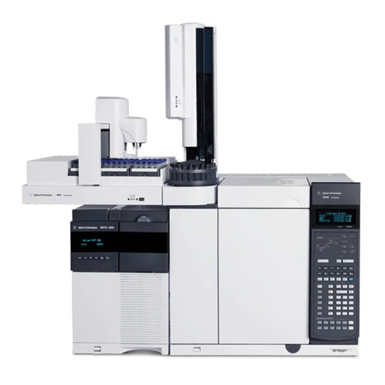
Introduction MSD Hardware Description 7890B GC Local control panel 5977 Series MSD power switch GC power switch Figure 1 5977 Series GC/MSD system, shown with Agilent 7890B GC 5977 Series MSD Operation Manual... - Page 16 Introduction The CI hardware allows the 5977 Series MSD to produce high-quality, classical CI spectra, which include molecular adduct ions. A variety of reagent gases can be used. In this manual, the term “CI MSD” refers to the G7040A MSD and upgraded G7038A and G7039A MSDs.
-
Page 17: Important Safety Warnings
Introduction Important Safety Warnings There are several important safety notices to always keep in mind when using the MSD. Many internal parts of the MSD carry dangerous voltages If the MSD is connected to a power source, even if the power switch is off, potentially dangerous voltages exist on: •... - Page 18 Introduction Many parts are dangerously hot Many parts of the GC/MSD operate at temperatures high enough to cause serious burns. These parts include but are not limited to: • The GC inlets • The GC oven and its contents including the column nuts attaching the column to a GC inlet, GC/MS interface, or GC detector •...
-
Page 19: Hydrogen Safety
Introduction Hydrogen Safety Using hydrogen as a GC carrier gas is potentially dangerous. WARNING When using hydrogen (H ) as the carrier gas or fuel gas, be aware that hydrogen WARNING can flow into the GC oven and create an explosion hazard. Therefore, be sure that the supply is turned off until all connections are made and ensure that the inlet and detector column fittings are either connected to a column or capped at all times when hydrogen is supplied to the instrument. - Page 20 Introduction Dangers unique to GC/MSD operation Hydrogen presents a number of dangers. Some are general, others are unique to GC or GC/MSD operation. Dangers include, but are not limited to: • Combustion of leaking hydrogen • Combustion due to rapid expansion of hydrogen from a high-pressure cylinder •...
- Page 21 Introduction Table 4 Hydrogen accumulation mechanisms Mechanism Results Mass spectrometer turned off A mass spectrometer can be shut down deliberately. It can also be shut down accidentally by an internal or external failure. There is a safety feature that will shut down the flow of carrier gas in the event of an MSD foreline pump shut down.
-
Page 22: Precautions
Introduction Once hydrogen has accumulated in a mass spectrometer, extreme caution must be WARNING used when removing it. Incorrect startup of a mass spectrometer filled with hydrogen can cause an explosion. After a power failure, the mass spectrometer may start up and begin the pumpdown WARNING process by itself. - Page 23 Introduction Operating precautions • Turn off the hydrogen at its source every time you shut down the GC or MSD. • Turn off the hydrogen at its source every time you vent the MSD (do not heat the capillary column without carrier gas flow). •...
-
Page 24: Safety And Regulatory Certifications
The 5977 Series MSD is designed and manufactured under a quality system registered to ISO 9001. Information The Agilent Technologies 5977 Series MSD meets the following IEC (International Electro-technical Commission) classifications: Equipment Class I, Laboratory Equipment, Installation Category II, Pollution Degree 2. - Page 25 Failure to comply with these precautions violates safety standards of design and the intended use of the instrument. Agilent Technologies assumes no liability for the customer’s failure to comply with these requirements.
-
Page 26: Electromagnetic Compatibility
Ensure that all peripheral devices are also certified. Ensure that appropriate cables are used to connect the device to peripheral equipment. Consult your equipment dealer, Agilent Technologies, or an experienced technician for assistance. Changes or modifications not expressly approved by Agilent Technologies could void the user’s authority to operate the equipment. -
Page 27: Cleaning/Recycling The Product
Introduction Cleaning/Recycling the Product To clean the unit, disconnect the power and wipe down with a damp, lint-free cloth. For recycling, contact your local Agilent sales office. Liquid Spillage Do not spill liquids on the MSD. Moving or Storing the MSD The best way to keep your MSD functioning properly is to keep it pumped down and hot, with carrier gas flow. -
Page 28: To Replace The Primary Fuses
Introduction To Replace the Primary Fuses Materials needed • Fuse, T12.5A, 250 V (2110-1398) – 2 required • Screwdriver, flat-blade (8730-0002) The most likely cause of failure of the primary fuses is a problem with the foreline pump. If the primary fuses in your MSD fail, check the foreline pump. Procedure Vent the MSD and unplug the power cord from the electrical outlet. - Page 29 Introduction Primary fuses in holders Figure 2 Primary fuses Repeat steps through for the other fuse. Always replace both fuses. Reconnect the MSD power cord to the electrical outlet. Pump down the MSD. 5977 Series MSD Operation Manual...
- Page 30 Introduction 5977 Series MSD Operation Manual...
-
Page 31: Installing Gc Columns
GC column. This chapter shows you how to install and condition a column. For correct column and flow selection, you must know what type of vacuum system your MSD has. The serial number tag on the lower front of the left side panel shows the model number. Agilent Technologies... -
Page 32: Columns
Use the Flow Calculation software and Table 5 to determine whether a given column will give acceptable flow with realistic head pressure. Table 5 Gas flows Model Feature G7035A G7036A G7037A G7038A G7039A G7040A High vacuum pump Diffusion... - Page 33 Installing GC Columns Conditioning columns Conditioning a column before it is connected to the GC/MSD interface is essential. See “To Condition a Capillary Column” on page 37. A small portion of the capillary column stationary phase is often carried away by the carrier gas.
-
Page 34: To Install A Capillary Column In A Split/Splitless Inlet
Installing GC Columns To Install a Capillary Column in a Split/Splitless Inlet Materials needed • Gloves, clean • Large (8650-0030) • Small (8650-0029) • Metric ruler • Wrench, open-end, 1/4-inch and 5/16-inch (8710-0510) • Capillary column • Column cutter, ceramic (5181-8836) or diamond (5183-4620) •... - Page 35 Installing GC Columns Always wear clean gloves while handling any parts that go inside the GC or analyzer CA UT IO N chambers. Procedure Cool the oven to room temperature. Wearing clean gloves, slide a septum, column nut, and conditioned ferrule onto the free end of the column (Figure 3).
- Page 36 Installing GC Columns Position the column so it extends 4 to 6 mm past the end of the ferrule (Figure Insulation cup Reducing nut Capillary column 4 to 6 mm Ferrule (inside nut) Inlet column nut Septum Figure 4 Installing a capillary column for a split/splitless inlet Slide the septum to place the nut and ferrule in the correct position.
-
Page 37: To Condition A Capillary Column
Installing GC Columns To Condition a Capillary Column Materials needed • Carrier gas, (99.9995% pure or better) • Wrench, open-end, 1/4-inch and 5/16-inch (8710-0510) Do not condition your capillary column with hydrogen. Hydrogen accumulation in WARNING the GC oven can result in an explosion. If you plan to use hydrogen as your carrier gas, first condition the column with ultrapure (99.999% or better) inert gas such as helium, nitrogen, or argon. -
Page 38: To Install A Capillary Column In The Gc/Ms Interface
Installing GC Columns To Install a Capillary Column in the GC/MS Interface This procedure is for the installation of a capillary column directly to the transfer line with a column nut. If you are using the Agilent capillary flow technology Quick Swap accessory, or a Purged Ultimate Union (PUU) see “To Prepare the Column Ends for a CFT Fitting”... - Page 39 Installing GC Columns Procedure Condition the column. (See “To Condition a Capillary Column” page 37.) The analyzer, GC/MS interface, and other components in the analyzer chamber WARNING operate at very high temperatures. Do not touch any part until you are sure it is cool. Dangerous voltages exist inside the analyzer chamber, which can result in fatal WARNING injury.
- Page 40 Installing GC Columns 13 Hand-tighten the nut. Ensure the position of the column does not change as you tighten the nut. 14 Check the GC oven to be sure that the column does not touch the oven walls. 15 Tighten the nut 1/4 to 1/2 turn. 16 Check the nut’s tightness after one or two heat cycles;...
-
Page 41: To Prepare The Column Ends For A Cft Fitting
Installing GC Columns To Prepare the Column Ends for a CFT Fitting Materials needed • SilTite ferrules: • 0.1- to 0.25-mm columns, pkg of 10 (5188-5361) • 0.32-mm columns, pkg of 10 (5188-5362) • 0.53-mm columns, pkg of 10 (5188-5363) •... - Page 42 Installing GC Columns Using the wrench and ferrule pre-swaging tool, tighten the nut a little at a time, occasionally checking to see if the ferrule is gripping the tube (see Figure 6). When the ferrule just starts to grip, notice position of the nut and then tighten by turning 45 to 60 degrees of rotation, but no more than 60 degrees (one flat).
- Page 43 Installing GC Columns Using a ceramic column cutter, trim the tubing at the small end of the ferrule leaving approximately 0.3 mm of tubing extending beyond the ferrule (Figure 8 on page 43). It is important that the ceramic column cutter have one side dedicated to only make contact with the column and the other side dedicated to riding on the edge of the metallic SilTite ferrule.
- Page 44 Installing GC Columns Check the end of the tube with a magnifier. The end of the tube need not be perfectly square, but should not have cracks which extend under the ferrule. Figure 9 shows a completed tube end. Figure 9 Tube end with internal nut and swaged SilTite ferrule Connect column to the Quick Swap or PUU with internal nuts and preswaged SilTite ferrules...
- Page 45 To Close the Analyzer Chamber To Pump Down the MSD in EI Mode To Move or Store the MSD This chapter describes how to perform some basic operating procedures for the Agilent 5977 Series GC/MSD using electron ionization. Agilent Technologies...
-
Page 46: Operating In Electron Ionization (Ei) Mode
Operating in Electron Ionization (EI) Mode Operating the MSD from the Data System The Agilent MassHunter Data Acquisition Workstation automates tasks such as pumping down, removing the ion source, monitoring settings, setting temperatures, tuning, and venting the MSD. These tasks are described in this chapter. - Page 47 Operating in Electron Ionization (EI) Mode To access a particular menu option: Press [Menu] until the desired menu appears. Press [Item] until the desired menu item appears. Use one or more of the following keys, as appropriate, to respond to prompts or select options: Use [Up] to increase the displayed value or to scroll up (such as in a message list).
-
Page 48: Lcp Status Messages
Operating in Electron Ionization (EI) Mode LCP status messages The following messages may be displayed on the LCP to inform you of the status of the MSD system. If the LCP is currently in Menu mode, cycle through the menus to return to Status mode. No messages will be displayed if an online instrument session is not currently running in MassHunter Data Acquisition. -
Page 49: To View System Status During Startup
Operating in Electron Ionization (EI) Mode <method> Complete <timestamp> The run and subsequent data processing are done. The same message appears even if the run was terminated prematurely. Method Loaded <method name> Method parameters were sent to the MSD. MS Locked by <computer name> MS parameters can only be changed from the MassHunter Data Acquisition. -
Page 50: Lcp Menus
Operating in Electron Ionization (EI) Mode LCP menus To access a particular menu option, press [Menu] until the desired menu appears, then press [Item] until the desired menu item appears. Table 6 through Table 11 on page 52 list the menus and selections. Many menu items, especially on the ChemStation, MS Parameters, and Maintenance NO T E menus, have no effect when the instrument is acquiring data. - Page 51 Operating in Electron Ionization (EI) Mode Table 7 Maintenance menu Action Description Prepare to vent Reminds you to shut down the GC then prepares the instrument for venting when [Yes/Select] is pressed. Pumpdown Initiates a pumpdown sequence. Hi Vac Soft Start Allows you to connect or disconnect the hi vac soft start feature.
- Page 52 Operating in Electron Ionization (EI) Mode Table 9 Network menu (continued) Action Description ChemStation IP Displays the IP address for the MassHunter Data Acquisition. GC IP Address Displays the IP address for the GC. Ping gateway Checks communication with the gateway. Ping ChemStation Checks communication with the MassHunter Data Acquisition.
-
Page 53: The Ei Gc/Msd Interface
Operating in Electron Ionization (EI) Mode The EI GC/MSD Interface The GC/MSD interface (Figure 11 on page 54) is a heated conduit into the MSD for the capillary column. It is bolted onto the right side of the analyzer chamber, with an O-ring seal. It has a protective cover which should be left in place. - Page 54 Operating in Electron Ionization (EI) Mode Heater sleeve Insulation Column Ionization chamber GC oven Analyzer chamber Heater/Sensor assembly Column end protrudes 1 to 2 mm into the ionization chamber. Figure 11 The EI GC/MSD interface 5977 Series MSD Operation Manual...
-
Page 55: Before You Turn On The Msd
Operating in Electron Ionization (EI) Mode Before You Turn On the MSD Verify the following before you turn on or attempt to operate the MSD. • The vent valve must be closed (the knob turned all the way clockwise). • All other vacuum seals and fittings must be in place and fastened correctly. The front side plate screw should not be tightened, unless hazardous carrier or reagent gasses are being used. -
Page 56: Pumping Down
Operating in Electron Ionization (EI) Mode Pumping Down The data system or local control panel helps you pump down the MSD. The process is mostly automated. Once you close the vent valve and turn on the main power switch (while pressing on the sideplate), the MSD pumps down by itself. -
Page 57: Venting The Msd
Operating in Electron Ionization (EI) Mode The MSD can be used to measure actual column flow. You inject a small amount of air or other unretained chemical and time how long it takes to reach the MSD. With this time measurement, you can calculate the column flow. -
Page 58: To View Msd Temperature And Vacuum In Manual Tune
Operating in Electron Ionization (EI) Mode To View MSD Temperature and Vacuum in Manual Tune You can also use the Local Control Panel to perform this task. See “Operating the MSD from the LCP” on page 46. Procedure In Instrument Control view, select Edit Tune Parameters from the Instrument menu to display the Manual Tune dialog. -
Page 59: To Set Monitors For Msd Temperature And Vacuum Status
Operating in Electron Ionization (EI) Mode To Set Monitors for MSD Temperature and Vacuum Status A monitor displays the current value of a single instrument parameter. They can be added to the standard instrument control window. Monitors can be set to change color if the actual parameter varies beyond a user-determined limit from its setpoint. - Page 60 Operating in Electron Ionization (EI) Mode To set a monitor’s alarm, double-click a monitor displayed in the Instrument Control view to open that monitor's dialog for setting alarms. a Select the Set Alarm check box. b Set the Warning Level, Alarm Level, and Below Minimum to appropriate values.
-
Page 61: To Set Analyzer Temperatures From The Instrument Control View
Operating in Electron Ionization (EI) Mode To Set Analyzer Temperatures from the Instrument Control View Setpoints for the MSD ion source and mass filter (quad) temperatures are stored in the current tune (*.u) file. When a method is loaded, the setpoints in the tune file associated with that method are downloaded automatically. - Page 62 Operating in Electron Ionization (EI) Mode To send the new temperature parameters to the currently loaded tune file and download these parameters to the MSD click Apply. Click Close to exit the dialog. If changes were made to any parameters the Save MS Tune File dialog displays.
-
Page 63: To Set The Gc/Msd Interface Temperature From Masshunter
Operating in Electron Ionization (EI) Mode To Set the GC/MSD Interface Temperature from MassHunter Procedure From Instrument Control view select Instrument>GC Edit Parameters. Click the Aux Heater icon to edit the interface temperature. Select On to turn on the heater and type the setpoint in the Value °C column. -
Page 64: To Monitor High Vacuum Pressure
Operating in Electron Ionization (EI) Mode To Monitor High Vacuum Pressure Pressure monitoring requires an optional G3397B Micro-Ion vacuum gauge. If you are using hydrogen as a carrier gas, do not turn on the Micro-Ion vacuum WARNING gauge if there is any possibility that hydrogen has accumulated in the analyzer chamber. - Page 65 Operating in Electron Ionization (EI) Mode The largest influence on operating pressure in EI mode is the carrier gas (column) flow. Table 13 lists typical pressures for various helium carrier gas flows. These pressures are approximate and will vary from instrument to instrument by as much as 30%.
-
Page 66: To Calibrate Column Flow Linear Velocity
Operating in Electron Ionization (EI) Mode To Calibrate Column Flow Linear Velocity Capillary columns must be calibrated prior to use with the MS. Procedure Set Data Acquisition for splitless manual injection and set up a real time plot to monitor m/z 28. Press [Prep Run] on the GC keypad. - Page 67 Operating in Electron Ionization (EI) Mode Click the Calc Length button in the If unretained peak holdup time is known section to display the Calculate Column Length dialog. 10 Verify that the parameters listed (temperature, inlet and outlet pressures, and gas type) are those used in the method to determine the holdup time. Change any parameters that are different than those used in your method.
- Page 68 Operating in Electron Ionization (EI) Mode Calculation for average linear velocity 100 L ------------- - Average linear velocity (cm/s) where: L = Length of the column in meters t = Retention time in seconds Calculation for volumetric flow rate 0.785 D --------------------------- - Volumetric flow rate (mL/min) = where:...
-
Page 69: To Tune The Msd In Ei Mode
Operating in Electron Ionization (EI) Mode To Tune the MSD in EI Mode You can also use the Local Control Panel to run the autotune that is currently loaded in MassHunter. See “Operating the MSD from the LCP” on page 46. Procedure Load the method that will be used for data acquisition. - Page 70 Operating in Electron Ionization (EI) Mode To evaluate the tune results, select Evaluate Tune from the Checkout menu. To view history of tune results, in the Instrument Control view select Checkout>View Previous Tunes..To manually tune your MSD or to perform special autotunes, from the View menu select Tune and Vacuum Control view.
-
Page 71: To Verify System Performance
Operating in Electron Ionization (EI) Mode To Verify System Performance Materials needed • 1 pg/µL (0.001 ppm) OFN sample (5188-5348) Verify the tune performance Verify that the system has been pumping down for at least 60 minutes. Set the GC oven temperature to 150 °C and the column flow to 1.0 mL/min. In the Instrument Control view, select Checkout Tune from the Checkout menu. -
Page 72: To Perform High-Mass Testing (5977 Series Msds)
Operating in Electron Ionization (EI) Mode To Perform High-Mass Testing (5977 Series MSDs) Materials needed • PFHT calibration sample (5188-5357) Procedure Load tune file ATUNE.U then auto tune the MSD. See “To Tune the MSD in EI Mode” on page 69. Resolve the PFHT.M method under x\5977\PFHT.M where x is the instrument number being used. - Page 73 Operating in Electron Ionization (EI) Mode Results Figure 12 PFHT high mass report 5977 Series MSD Operation Manual...
- Page 74 Operating in Electron Ionization (EI) Mode Results will indicate the recommended amount to adjust AMU offset for high-mass. If your results are within 5 units of the targeted amount, there is no need to make adjustments. Adjustments Verify ATUNE.U has been loaded. In Instrument Control view select Edit Tune Parameters from the Instrument menu to display the Manual Tune dialog.
-
Page 75: To Open The Msd Covers
Operating in Electron Ionization (EI) Mode To Open the MSD Covers If you need to open one of the MSD covers, follow these procedures. To remove the analyzer window cover Press down on the rounded area on the top of the window, tilt the window slightly forward and lift off the MSD. -
Page 76: To Vent The Msd
Operating in Electron Ionization (EI) Mode To Vent the MSD Procedure In Instrument Control view select GC Parameters from the Instrument menu to display the GC Edit Parameters dialog. Select and set the oven Oven temperature to room temperature. Also select Aux Heaters (MSD Transfer line) and set those temperatures to room temperature. - Page 77 Operating in Electron Ionization (EI) Mode In the Instrument Control view, Instrument menu, select MS Vacuum Control to display the Vacuum Control dialog. Remove the analyzer window cover (see “To Open the MSD Covers” page 75). Click Vent to begin the automated shutdown of the MSD. Follow the instructions presented.
-
Page 78: To Open The Analyzer Chamber
Operating in Electron Ionization (EI) Mode To Open the Analyzer Chamber Materials needed • Gloves, clean, lint-free • Large (8650-0030) • Small (8650-0029) • Wrist strap, antistatic • Small (9300-0969) • Medium (9300-1257) • Large (9300-0970) Electrostatic discharges to analyzer components are conducted to the side board CA UT IO N where they can damage sensitive components. - Page 79 Operating in Electron Ionization (EI) Mode Loosen the side plate thumbscrews if they are fastened. The rear side plate thumbscrew should be unfastened during normal use. It is only fastened during shipping. The front side plate thumbscrew should only be fastened for CI operation or if hydrogen or other flammable or toxic substances are used for carrier gas.
-
Page 80: To Close The Analyzer Chamber
Operating in Electron Ionization (EI) Mode To Close the Analyzer Chamber Materials needed • Gloves, clean, lint-free • Large (8650-0030) • Small (8650-0029) Procedure Ensure all the internal analyzer electrical leads are correctly attached. Wiring is the same for both the standard EI and CI ion sources. The extractor EI ion source has an extra wire leading to the extractor lens. - Page 81 Operating in Electron Ionization (EI) Mode QUADRUPOLE Blue wire to entrance lens ENTR LENS Orange wire to ion focus lens White wires to filament 1 FILAMENT - 1 Red wire to repeller FILAMENT - 2 Black wires to Brown extractor filament 2 wire to extractor lens...
- Page 82 Operating in Electron Ionization (EI) Mode Filament 1 FB = Feedthrough Board (white wires from FB) Entrance lens (blue wire Ion source from FB) heater wires Repeller (red wire from FB) Ion focus lens (orange wire from FB) Ion source sensor wires Filament 2 (black wires...
- Page 83 Operating in Electron Ionization (EI) Mode The front thumbscrew must be fastened for CI operation or if hydrogen (or other WARNING hazardous gas) is being used as the GC carrier gas. In the unlikely event of an explosion, it may prevent the side plate from opening. Do not overtighten the thumbscrew;...
-
Page 84: To Pump Down The Msd In Ei Mode
Operating in Electron Ionization (EI) Mode To Pump Down the MSD in EI Mode You can also use the Local Control Panel to perform this task. See “Operating the MSD from the LCP” on page 46. Make sure your MSD meets all the conditions listed in the introduction to this WARNING chapter (page... - Page 85 Operating in Electron Ionization (EI) Mode Press lightly on the side board to ensure a correct seal. Press on the metal box on the side board. The foreline pump will make a gurgling noise. This noise should stop within a minute.
-
Page 86: To Move Or Store The Msd
Operating in Electron Ionization (EI) Mode To Move or Store the MSD Materials needed • Ferrule, blank (5181-3308) • Interface column nut (05988-20066) • Wrench, open-end, 1/4-inch × 5/16-inch (8710-0510) Procedure Vent the MSD (See “To Vent the MSD” on page 76). Remove the column and install a blank ferrule and interface nut. - Page 87 The MSD must remain upright at all times. If you need to ship your MSD to another CA UT IO N location, contact your Agilent Technologies service representative for advice about packing and shipping. 5977 Series MSD Operation Manual...
- Page 88 Operating in Electron Ionization (EI) Mode 5977 Series MSD Operation Manual...
- Page 89 The software contains instructions for setting the reagent gas flow and for performing CI autotunes. Autotunes are provided for positive CI (PCI) with methane reagent gas and for negative CI (NCI) with any reagent gas. Agilent Technologies...
-
Page 90: Operating In Chemical Ionization (Ci) Mode
Operating in Chemical Ionization (CI) Mode General Guidelines • Always use the highest purity methane (and other reagent gases, if applicable). Methane must be at least 99.9995% pure. • Always verify the MSD is performing well in EI mode before switching to CI. “To Verify System Performance”... -
Page 91: The Ci Gc/Msd Interface
Operating in Chemical Ionization (CI) Mode The CI GC/MSD Interface The CI GC/MSD interface (Figure 15 on page 92) is a heated conduit into the MSD for the capillary column. It is bolted onto the right side of the analyzer chamber, with an O-ring seal and has a protective cover, which should be left in place. - Page 92 Operating in Chemical Ionization (CI) Mode Spring-loaded seal GC oven Reagent gas in Column end protrudes 1 to 2 mm into the ionization chamber. Figure 15 The CI GC/MSD interface See Also “To Install a Capillary Column in the GC/MS Interface” on page 38.
-
Page 93: Ci Autotune
Operating in Chemical Ionization (CI) Mode CI Autotune After the reagent gas flow is adjusted, the lenses and electronics of the MSD should be tuned. See “Reagent gas settings” on page 94. Perfluoro-5,8-dimethyl-3,6,9-trioxidodecane (PFDTD) is used as the calibrant. Instead of flooding the entire vacuum chamber, the PFDTD is introduced directly into the ionization chamber through the GC/MSD interface by means of the gas flow control module. -
Page 94: N/A Not Available
Operating in Chemical Ionization (CI) Mode Table 15 Reagent gas settings Reagent gas Methane Isobutane Ammonia Ion polarity Positive Negative Positive Negative Positive Negative 150 A 50 A 150 A 50 A 150 A 50 A 35 A Emission Electron 150 eV 150 eV 150 eV... -
Page 95: To Operate The Ci Msd
Operating in Chemical Ionization (CI) Mode To Operate the CI MSD Operating your MSD in the CI mode is slightly more complicated than operating in the EI mode. After tuning, gas flow, source temperature (Table 16), and electron energy may need to be optimized for your specific analyte. -
Page 96: To Switch From The Standard Or Inert Ei Ion Source To The Ci Ion Source
Operating in Chemical Ionization (CI) Mode To Switch from the Standard or Inert EI ion source to the CI Ion Source Always verify MSD performance in EI before switching to CI operation. CA UT IO N Always set up the CI MSD in PCI first, even if you are going to run NCI. Procedure Vent the MSD. -
Page 97: To Switch From The Extractor Ei Ion Source To The Ci Ion Source
Operating in Chemical Ionization (CI) Mode To Switch from the Extractor EI Ion Source to the CI Ion Source Always verify MSD performance in EI before switching to CI operation. CA UT IO N Always set up the CI MSD in PCI first, even if you are going to run NCI. Electrostatic discharges to analyzer components are conducted to the side board CA UT IO N where they can damage sensitive components. -
Page 98: To Pump Down The Msd In Ci Mode
Operating in Chemical Ionization (CI) Mode To Pump Down the MSD in CI Mode This procedure assumes that the instrument will eventually be PCI tuned using methane after the system is stable. Procedure Follow the instructions for the EI MSD. “To Pump Down the MSD in EI Mode”... -
Page 99: To Set Up The Software For Ci Operation
Operating in Chemical Ionization (CI) Mode To Set Up the Software for CI Operation Always verify GC/MS performance in EI before switching to CI operation. CA UT IO N Procedure From the Tune and Vacuum Control view, select Load Tune Parameters from the File menu and load the tune file PCICH4.U. - Page 100 Operating in Chemical Ionization (CI) Mode • Ion polarity Always set up in PCI with methane first, then switch to your desired ion polarity and reagent gas. • Abundance target Adjust higher or lower to get the desired signal abundance. Higher signal abundance also gives higher noise abundance. This is adjusted for data acquisition by setting the EMV in the method.
-
Page 101: To Operate The Reagent Gas Flow Control Module
Operating in Chemical Ionization (CI) Mode To Operate the Reagent Gas Flow Control Module After the system has been switched from EI to CI mode, or vented for any other reason, CA UT IO N the MS must be baked out for at least 2 hours before tuning. Continuing with CI autotune if the MS has an air leak or large amounts of water will CA UT IO N result in severe ion source contamination. - Page 102 Operating in Chemical Ionization (CI) Mode Enter the reagent gas flow setpoint in the Flow field. This value is entered as a percentage of maximum flow rate. The recommended flow is 20% for a PCI source and 40% for an NCI source. The flow control hardware remembers the flow setting for each gas.
- Page 103 Operating in Chemical Ionization (CI) Mode CI ion source Gas A (methane) supply Shutoff Gas A valve select valve Mass flow controller Gas B select valve GC/MSD Calibration Gas B interface valve (other) supply Restrictor Calibration GC column vial Figure 16 Reagent gas flow control module schematic Table 18 Flow control module state diagram...
-
Page 104: To Set Up Methane Reagent Gas Flow
Operating in Chemical Ionization (CI) Mode To Set Up Methane Reagent Gas Flow The reagent gas flow must be adjusted for maximum stability before tuning the CI system. Do the initial setup with methane in positive chemical ionization (PCI) mode. No flow adjustment procedure is available for NCI, as no negative reagent ions are formed. - Page 105 Operating in Chemical Ionization (CI) Mode Examine the displayed profile scan of the reagent ions. • There should be no visible peak at m/z 32. A peak there indicates an air leak. Repair the leak before proceeding. Operating in the CI mode with an air leak will rapidly contaminate the ion source.
-
Page 106: To Use Other Reagent Gases
Operating in Chemical Ionization (CI) Mode To Use Other Reagent Gases This section describes the use of isobutane or ammonia as the reagent gas. You should be familiar with operating the CI-equipped 5977 Series MSD with methane reagent gas before attempting to use other reagent gases. Do not use nitrous oxide as a reagent gas. - Page 107 Operating in Chemical Ionization (CI) Mode Isobutane CI Isobutane (C ) is commonly used for chemical ionization when less fragmentation is desired in the chemical ionization spectrum. This is because the proton affinity of isobutane is higher than that of methane; hence, less energy is transferred in the ionization reaction.
- Page 108 Operating in Chemical Ionization (CI) Mode There is no CI autotune for isobutane or ammonia in PCI. If you wish to run NCI with isobutane or ammonia, load NCICH4.U or an existing NCI tune file for the specific gas. For more information on CI operation using ammonia, refer to Agilent Application Note “Implementation of Ammonia Reagent Gas for Chemical Ionization on the Agilent 5977 Series MSDs”...
-
Page 109: To Switch From The Ci Ion Source To The Standard Or Inert Ei Ion Source
Operating in Chemical Ionization (CI) Mode To Switch from the CI Ion Source to the Standard or Inert EI Ion Source Procedure Always wear clean gloves while touching the analyzer or any other parts that go inside CA UT IO N the analyzer chamber. -
Page 110: To Switch From The Ci Ion Source To The Extractor Ei Ion Source
Operating in Chemical Ionization (CI) Mode To Switch from the CI Ion Source to the Extractor EI Ion Source Always wear clean gloves while touching the analyzer or any other parts that go inside CA UT IO N the analyzer chamber. Electrostatic discharges to analyzer components are conducted to the side board CA UT IO N where they can damage sensitive components. -
Page 111: To Perform A Pci Autotune (Methane Only)
Operating in Chemical Ionization (CI) Mode To Perform a PCI Autotune (Methane Only) Always verify MSD performance in EI before switching to CI operation. Always set up CA UT IO N the CI MSD in PCI first, even if you are going to run NCI. Avoid tuning more often than is absolutely necessary;... - Page 112 Operating in Chemical Ionization (CI) Mode Figure 18 PCI autotune report 5977 Series MSD Operation Manual...
-
Page 113: To Perform An Nci Autotune (Methane Reagent Gas)
Operating in Chemical Ionization (CI) Mode To Perform an NCI Autotune (Methane Reagent Gas) Always verify MSD performance in EI before switching to CI operation. See “To Verify CA UT IO N System Performance” on page 71. Always set up the CI MSD in PCI with methane as the reagent gas first, even if you are going to be using a different reagent gas or going to run NCI. - Page 114 Operating in Chemical Ionization (CI) Mode Figure 19 NCI autotune 5977 Series MSD Operation Manual...
-
Page 115: To Verify Pci Performance
Operating in Chemical Ionization (CI) Mode To Verify PCI Performance Materials needed • Benzophenone, 100 pg/L (8500-5440) Always verify MSD performance in EI before switching to CI operation. See “To Verify CA UT IO N System Performance” on page 71. Always set up the CI MSD in PCI first, even if you are going to run NCI. -
Page 116: To Verify Nci Performance
Operating in Chemical Ionization (CI) Mode To Verify NCI Performance This procedure is for EI/PCI/NCI MSDs only. Materials needed • Octafluoronaphthalene (OFN), 100 fg/µL (5188-5347) Always verify MSD performance in EI before switching to CI operation. See “To Verify CA UT IO N System Performance”... -
Page 117: To Monitor Ci Mode High Vacuum Pressure
Operating in Chemical Ionization (CI) Mode To Monitor CI Mode High Vacuum Pressure If you are using hydrogen as a carrier gas, do not turn on the Micro-Ion vacuum WARNING gauge if there is any possibility that hydrogen has accumulated in the manifold. Read “Hydrogen Safety”... - Page 118 Operating in Chemical Ionization (CI) Mode Table 20 Mass flow controller settings and typical pressure readings Pressure (Torr) Methane Ammonia EI/PCI/NCI MSD EI/PCI/NCI MSD (Turbo pump) (Turbo pump) 10 –5 –5 × × 10 –5 –5 × × 10 –4 –5 ×...
-
Page 119: General Maintenance
To Clean the EI Ion Source To Assemble a Standard or Inert EI Ion Source To Assemble the Extractor EI Ion Source To Replace a Filament in an EI Ion Source To Install the EI Ion Source To Replace the Electron Multiplier Horn Agilent Technologies... -
Page 120: Before Starting
General Maintenance Before Starting You can perform much of the maintenance required by your MSD. For your safety, read all of the information in this introduction before performing any maintenance tasks. Table 21 Maintenance schedule Task Every week Every 6 months Every year As needed Tune the MSD... - Page 121 General Maintenance Keep a record of system performance (tune reports) and maintenance operations performed. This makes it easier to identify variations from normal operation and to take corrective action. Tools, spare parts, and supplies Some of the required tools, spare parts, and supplies are included in the GC shipping kit, MSD shipping kit, or MSD tool kit.
- Page 122 General Maintenance Some procedures in this chapter require access to the inside of the MSD while the power switch is on. Do not remove any of the electronics safety covers in any of these procedures. To reduce the risk of electric shock, follow the procedures carefully.
-
Page 123: Electrostatic Discharge
General Maintenance Chemical residue Only a small portion of your sample is ionized by the ion source. The majority of any sample passes through the ion source without being ionized. It is pumped away by the vacuum system. As a result, the exhaust from the foreline pump will contain traces of the carrier gas and your samples. - Page 124 General Maintenance ESD to sensitive components on the side board. ESD damage may not cause immediate failure, but it will gradually degrade the performance and stability of your MSD. When you work on or near printed circuit boards or when you work on components with wires, contacts, or cables connected to printed circuit boards, always use a grounded antistatic wrist strap and take other antistatic precautions.
-
Page 125: Maintaining The Vacuum System
General Maintenance Maintaining the Vacuum System Periodic maintenance As listed earlier in Table 21 on page 120, some maintenance tasks for the vacuum system must be performed periodically. These include: • Checking the foreline pump fluid (every week) • Checking the calibration vial(s) (every 6 months) •... -
Page 126: Maintaining The Analyzer
General Maintenance Maintaining the Analyzer Scheduling None of the analyzer components require periodic maintenance. Some tasks, however, must be performed when MSD behavior indicates they are necessary. These tasks include: • Cleaning the ion source • Replacing filaments • Replacing the electron multiplier horn The Agilent 5977 Series MSD Troubleshooting and Maintenance Manual provides information about symptoms that indicate the need for analyzer maintenance. - Page 127 General Maintenance Some parts can be damaged by electrostatic discharge The wires, contacts, and cables connected to the analyzer components can carry electrostatic discharges (ESD) to the electronics boards to which they are connected. This is especially true of the mass filter (quadrupole) contact wires which can conduct ESD to sensitive components on the side board.
-
Page 128: To Remove The Ei Ion Source
General Maintenance To Remove the EI Ion Source Materials needed • Gloves, clean, lint-free • Large (8650-0030) • Small (8650-0029) • Pliers, long-nose (8710-1094) Procedure Vent the MSD. See “To Vent the MSD” on page 76. Open the analyzer chamber. See “To Open the Analyzer Chamber”... - Page 129 General Maintenance If you are using an extractor EI ion source, disconnect the eight wires from the ion source. Do not bend the wires any more than necessary (See Figure 20 on page 130 and Table 23). Table 23 Extractor EI ion source wires Wire color Connects to Number of leads...
- Page 130 General Maintenance Ion source Source feedthrough board Thumbscrews Extractor wire Source heater and temperature sensor wires Source radiator Figure 20 Removing the EI ion source 5977 Series MSD Operation Manual...
-
Page 131: To Disassemble The Standard Or Inert Ei Ion Source
General Maintenance To Disassemble the Standard or Inert EI Ion Source Materials needed • Gloves, clean, lint-free • Large (8650-0030) • Small (8650-0029) • Hex ball driver, 1.5 mm (8710-1570) • Hex ball driver, 2.0 mm (8710-1804) • Wrench, open-end, 10 mm (8710-2353) Procedure Remove the ion source. - Page 132 General Maintenance 14 14 15 15 15 16 16 Figure 21 Disassembling the standard or inert EI ion source Table 24 Parts list for the standard or inert EI ion source (Figure Item number Item description Gold plated set screw Gold plated screw Interface socket Source body...
- Page 133 General Maintenance Table 24 Parts list for the standard or inert EI ion source (Figure 21) (continued) Item number Item description Spring washer Lens insulator Entrance lens Ion focus lens Repeller insulator Repeller Flat washer Belleville spring washer Repeller nut Source heater block assembly Repeller block insert 5977 Series MSD Operation Manual...
-
Page 134: To Disassemble The Extractor Ei Ion Source
General Maintenance To Disassemble the Extractor EI Ion Source Materials needed • Gloves, clean, lint-free • Large (8650-0030) • Small (8650-0029) • Hex ball driver, 1.5 mm (8710-1570) • Hex ball driver, 2.0 mm (8710-1804) • Wrench, open-end, 10 mm (8710-2353) Procedure Remove the ion source. - Page 135 General Maintenance Figure 22 Disassembling the extractor EI ion source Table 25 Parts list for extractor ion source (Figure Item number Item description Setscrews Screws Source body Extractor lens Extractor lens insulator Filaments 5977 Series MSD Operation Manual...
- Page 136 General Maintenance Table 25 Parts list for extractor ion source (Figure 22) (continued) Item number Item description Spring washer Lens insulator Entrance lens Ion focus lens Repeller insulator Repeller Flat washer Belleville spring washer Repeller nut Source heater block assembly Insulator 5977 Series MSD Operation Manual...
-
Page 137: To Clean The Ei Ion Source
General Maintenance To Clean the EI Ion Source Materials needed • Abrasive paper (5061-5896) • Alumina abrasive powder (8660-0791) • Aluminum foil, clean • Cloths, clean (05980-60051) • Cotton swabs (5080-5400) • Glass beakers, 500 mL • Gloves, clean, lint-free •... - Page 138 General Maintenance Collect the following parts to be cleaned for an extractor EI ion source: (See Figure 23 on page 139.) • Repeller • Insulator • Source body • Extractor lens • Ion focus lens • Entrance lens These are the parts that contact the sample or ion beam. The other parts normally should not require cleaning.
- Page 139 General Maintenance Standard or inert EI ion source parts to be cleaned Source body Ion focus lens Entrance lens Drawout Drawout plate Interface socket cylinder Extractor EI ion source parts to be cleaned Insulator Extractor lens Repeller Entrance Source body Ion focus lens lens Figure 23...
- Page 140 General Maintenance Procedure The filaments, source heater assembly, and insulators cannot be cleaned CA UT IO N ultrasonically. Replace these components if major contamination occurs. If the contamination is serious, such as an oil backflow into the analyzer, seriously consider replacing the contaminated parts. Abrasively clean the surfaces that contact the sample or ion beam.
- Page 141 General Maintenance Let the parts cool before you handle them. WARNING Take care to avoid recontaminating cleaned and dried parts. Put on new, clean gloves NO T E before handling the parts. Do not set the cleaned parts on a dirty surface. Set them only on clean, lint-free cloths.
-
Page 142: To Assemble A Standard Or Inert Ei Ion Source
General Maintenance To Assemble a Standard or Inert EI Ion Source Materials needed • Gloves, clean, lint-free • Large (8650-0030) • Small (8650-0029) • Hex ball driver, 1.5 mm (8710-1570) • Hex ball driver, 2.0 mm (8710-1804) • Wrench, open-end, 10 mm (8710-2353) Procedure ... - Page 143 General Maintenance Do not overtighten the interface socket. Overtightening could strip the threads. CA UT IO N 14 14 15 15 15 16 16 Figure 24 Assembling the standard or inert EI ion source Table 26 Parts list for the standard or inert EI ion source (Figure Item number Item description...
- Page 144 General Maintenance Table 26 Parts list for the standard or inert EI ion source (Figure 24) (continued) Item number Item description Source body Drawout cylinder Drawout plate 4-turn filament Spring washer Lens insulator Entrance lens Ion focus lens Repeller insulator Repeller Belleville spring washer Flat washer...
-
Page 145: To Assemble The Extractor Ei Ion Source
General Maintenance To Assemble the Extractor EI Ion Source Materials needed • Gloves, clean, lint-free • Large (8650-0030) • Small (8650-0029) • Hex ball driver, 1.5 mm (8710-1570) • Hex ball driver, 2.0 mm (8710-1804) • Wrench, open-end, 10 mm (8710-2353) Procedure ... - Page 146 General Maintenance Attach the repeller assembly to the source body using the two gold plated screws and spring washers. Install the filaments using the two gold plated screws and spring washers. Figure 25 Assembling the extractor EI ion source Table 27 Parts list for the extractor EI ion source (Figure Item number...
- Page 147 General Maintenance Table 27 Parts list for the extractor EI ion source (Figure 25) (continued) Item number Item description Extractor lens Extractor lens insulator Filaments Spring washer Lens insulator Entrance lens Ion focus lens Repeller insulator Repeller Flat washer Belleville spring washer Repeller nut Source heater block assembly Repeller block insert...
-
Page 148: To Replace A Filament In An Ei Ion Source
General Maintenance To Replace a Filament in an EI Ion Source Materials needed • Filament assembly (G2590-60053) • Gloves, clean, lint-free • Large (8650-0030) • Small (8650-0029) • Hex ball driver, 1.5-mm (8710-1570) Procedure Vent the MSD. See “Venting the MSD” on page 57. - Page 149 General Maintenance Gold plated screws and washers Figure 26 Changing the filament Secure the new filament(s) with the gold plated screw and washer. After installing the filament, verify that it is not grounded to the source body. Install the ion source. See “To Install the EI Ion Source”...
-
Page 150: To Install The Ei Ion Source
General Maintenance To Install the EI Ion Source Materials needed • Gloves, clean, lint-free • Large (8650-0030) • Small (8650-0029) • Pliers, long-nose (8710-1094) Procedure Slide the ion source into the source radiator. Ion source Source feedthrough board Thumbscrews Extractor wire Source heater and temperature sensor wires... -
Page 151: To Replace The Electron Multiplier Horn
General Maintenance To Replace the Electron Multiplier Horn Materials needed • Electron multiplier horn (G3170-80103) • Gloves, clean, lint-free • Large (8650-0030) • Small (8650-0029) Procedure Vent the MSD. See “To Vent the MSD” on page 76. Open the analyzer chamber. See “To Open the Analyzer Chamber”... - Page 152 General Maintenance Remove the electron multiplier horn. Install the new electron multiplier horn. Close the retaining clip. on the outside The signal pin on the horn must rest of the loop in the Do not contact strip. put the signal pin on the inside of the loop in the contact strip.
-
Page 153: Ci Maintenance
To Assemble the CI Ion Source To Install the CI Ion Source To Replace a Filament in a CI Ion Source This chapter describes maintenance procedures and requirements that are unique to 5977 Series MSDs equipped with the chemical ionization hardware. Agilent Technologies... -
Page 154: General Information
CI Maintenance General Information Ion source cleaning The main effect of operating the MSD in CI mode is the need for more frequent ion source cleaning. In CI operation, the ion source chamber is subject to more rapid contamination than in EI operation because of the higher source pressures required for CI. -
Page 155: To Install The Ci/Extractor Interface Tip Seal
CI Maintenance To Install the CI/Extractor Interface Tip Seal Materials needed • Interface tip seal (G1999-60412) The interface tip seal must be in place for the CI ion source and the Extraction source. Electrostatic discharges to analyzer components are conducted to the side board CA UT IO N where they can damage sensitive components. - Page 156 You can align the analyzer and interface by wiggling the side plate on its hinge. If the analyzer still will not close, contact your Agilent Technologies service representative. 5977 Series MSD Operation Manual...
-
Page 157: To Remove The Ci Ion Source
CI Maintenance To Remove the CI Ion Source Materials needed • Gloves, clean, lint-free • Large (8650-0030) • Small (8650-0029) • Pliers, long-nose (8710-1094) Procedure Vent the MSD. See “To Vent the MSD” on page 76. Open the analyzer chamber. See “To Open the Analyzer Chamber”... - Page 158 CI Maintenance Table 28 Standard CI ion source wires Wire color Connects to Number of leads Blue Entrance lens Orange Ion focus White Filament 1 (top filament) Repeller Black Filament 2 (bottom filament) Trace the wires for the ion source heater and temperature sensor to the feedthrough board.
-
Page 159: To Disassemble The Ci Ion Source
CI Maintenance To Disassemble the CI Ion Source Materials needed • Gloves, clean, lint-free • Large (8650-0030) • Small (8650-0029) • Hex ball driver, 1.5 mm (8710-1570) • Hex ball driver, 2.0 mm (8710-1804) • Wrench, open-end, 10 mm (8710-2353) Procedure ... - Page 160 CI Maintenance Figure 29 Disassembling the CI ion source Table 29 Parts list for the CI ion source (Figure Item number Item description Setscrew Filament screw CI interface tip seal CI repeller insulator CI lens insulator CI drawout cylinder CI drawout plate 5977 Series MSD Operation Manual...
- Page 161 CI Maintenance Table 29 Parts list for the CI ion source (Figure 29) (continued) Item number Item description CI ion source heater block assembly Entrance lens CI ion source body CI ion focus lens CI repeller CI filament Dummy filament Tool box 5977 Series MSD Operation Manual...
-
Page 162: To Clean The Ci Ion Source
CI Maintenance To Clean the CI Ion Source Materials needed • Abrasive paper (5061-5896) • Alumina abrasive powder (8660-0791) • Aluminum foil, clean • Cloths, clean (05980-60051) • Cotton swabs (5080-5400) • Glass beakers, 500 mL • Gloves, clean, lint-free •... - Page 163 CI Maintenance Clean the parts as described in “To Clean the EI Ion Source” on page 137. If the insulators are dirty, clean them with a cotton swab dampened with reagent-grade CA UT IO N methanol. If that does not clean the insulators, replace them. Do not abrasively or ultrasonically clean the insulators.
-
Page 164: To Assemble The Ci Ion Source
CI Maintenance To Assemble the CI Ion Source Materials needed • Gloves, clean, lint-free • Large (8650-0030) • Small (8650-0029) • Hex ball driver, 1.5 mm (8710-1570) • Hex ball driver, 2.0 mm (8710-1804) • Wrench, open-end, 10 mm (8710-2353) Procedure ... - Page 165 CI Maintenance Figure 31 Assembling the CI ion source Table 30 Parts list for the CI ion source (Figure Item number Item description Setscrew Filament screw CI interface tip seal CI repeller insulator CI lens insulator CI drawout cylinder 5977 Series MSD Operation Manual...
- Page 166 CI Maintenance Table 30 Parts list for the CI ion source (Figure 31) (continued) Item number Item description CI drawout plate CI ion source heater block assembly Entrance lens CI ion source body CI ion focus lens CI repeller CI filament Dummy filament Tool box 5977 Series MSD Operation Manual...
-
Page 167: To Install The Ci Ion Source
CI Maintenance To Install the CI Ion Source Materials needed • Gloves, clean, lint-free • Large (8650-0030) • Small (8650-0029) • Pliers, long-nose (8710-1094) Procedure Slide the ion source into the source radiator. Ion source Source feedthrough board Thumbscrews Source heater and temperature sensor wires Source radiator... -
Page 168: To Replace A Filament In A Ci Ion Source
CI Maintenance To Replace a Filament in a CI Ion Source Materials needed • Filament assembly (G2590-60053) • Gloves, clean, lint-free • Large (8650-0030) • Small (8650-0029) • Hex ball driver, 1.5-mm (8710-1570) Procedure Vent the MSD. See “Venting the MSD” on page 57. - Page 169 CI Maintenance Secure the new filament with the gold plated screw and washer. After installing the filament, verify that it is not grounded to source body. Install the ion source. See “To Install the CI Ion Source” on page 167. Close the analyzer chamber.
- Page 170 CI Maintenance 5977 Series MSD Operation Manual...
- Page 172 Agilent Technologies © Agilent Technologies, Inc. Printed in USA, February 2013 *G3870-90003* G3870-90003...