Table of Contents
Advertisement
Advertisement
Table of Contents

Related Manuals for Siemens SIPART DR22


Summary of Contents for Siemens SIPART DR22
- Page 1 Manual Edition12/2006 Controller SIPART DR22 6DR2210 sipart...
-
Page 3: Sipart Dr22 6Dr2210
SIPART DR22 6DR2210 Edition 12/2006 Manual SIPART DR22 6DR2210 C79000-G7476-C154-03... - Page 4 + 24 V 3AO/3BE FdEF + 5 V Slot 5 FCon Options FPoS line – APSt FPST RS 232 « RS 485 PROFIBUS Slot 4 6DR2210-4 24 V UC 6DR2210-5 115/230 V AC switchable Slot Terminal SIPART DR22 6DR2210 C79000-G7476-C154-03...
-
Page 5: Edition
Copyright e Siemens AG 2006 All rights reserved Disclaimer of Liability The reproduction, transmission or use of this docu-... - Page 6 Trademarks SIMATICR, SIPARTR, SIRECR, SITRANSR registered trademarks of Siemens AG. Third parties using for their own purposes any other names in this document which refer to trade- marks might infringe upon the rights of the trademark owners. SIPART DR22 6DR2210...
-
Page 7: Table Of Contents
..........SIPART DR22 6DR2210... - Page 8 ............... . SIPART DR22 6DR2210...
-
Page 9: Technical Description
115/230 V AC or special plug at 24 V UC Clamps, pluggable Assembly and installation instructions Order number C79000-M7474-C38 D Basic equipment The following variants of the SIPART DR22 are available: Order number Power Supply 6DR2210-4 24 V UC... -
Page 10: Range Of Application
The named programming possibilities guarantee a great flexibility in the use of the controller and allow fast, easy adapting of the device to the problem so that the SIPART DR22 can be used universally for control jobs in processing engineering, e.g. as... -
Page 11: Design (Hardware)
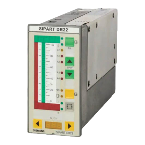
(BE, 0/24 V) and eight digital outputs (BA, 0/24 V, 50 mA) which can be used for different func- tions depending on the configuration. The SIPART DR22 also has three analog outputs (AA) which can all supply a current signal from 0 to 20 mA or 4 to 20 mA and be assigned to different variables. - Page 12 5 digital inputs 3 analog outputs/3 digital inputs 1 analog output with digital fault output (y function) with remote supply hold 3 analog inputs Power supply unit Casing Front module Figure 1-1 Front view of the SIPART DR22 SIPART DR22 6DR2210 C79000-G7476-C154-03...
- Page 13 Slot 4 (SES: RS 232/ RS 485, Profibus DP) Grounding screw DIN rail (delivered with the interface relay) 10 Selector switch Mains voltage 11 Mains plug 12 Power supply unit Figure 1-2 Rear view of the SIPART DR22 SIPART DR22 6DR2210 C79000-G7476-C154-03...
-
Page 14: Function Principle
Then the data are output to the display elements, the analog outputs and the digital outputs as well as storage of the calculated variables on standby for the serial interface transmitter. The interface traffic runs in interrupt mode. SIPART DR22 6DR2210 C79000-G7476-C154-03... -
Page 15: Description Of The Option Modules
A large number of prepared functions for controlling processing plants as well as machines and apparatus is stored in the set value memory of the SIPART DR22. The user programs the instrument himself by selecting the desired functions by setting structure switches. The total functioning of the instrument is given by the combination of the individual structure switches. - Page 16 (AE4/AE5); the range and the other parameters are set in the CAE4/CAE5 menu. The sensor- specific characteristics (linearization) for thermocouples and Pt100 resistance thermometers are stored in the contoller’s program memory and are automatically taken into account. No settings need to be made on the module itself. SIPART DR22 6DR2210 C79000-G7476-C154-03...
- Page 17 In this case the capacitors (1 μF) must be removed and replaced with low capacitance capacitors. The 68 V suppressor diodes parallel to the capacitors act additionally to reduce the induced voltage. SIPART DR22 6DR2210 C79000-G7476-C154-03...
- Page 18 If data communication to the y processor is interrupted, the analog output receives its last hold value. The processor reads the current variable first when data traffic is recovered. The out- put current is maintained if: SIPART DR22 6DR2210 C79000-G7476-C154-03...
- Page 19 1.4 Function principle 1.4.2 Description of the option modules -- the self diagnostics of the CPU (see chapter 1.4.3, page 20) responds. -- the supply voltage of the SIPART DR22 fails and the y -module is powered externally. hold -- all modules except the power supply unit are removed (if the y...
- Page 20 D Serial interface for RS 232 or RS 485 with electrical isolation Can be inserted in slot 4. For connecting the controller SIPART DR22 to a master system for control and monitoring. All process variables can be sent, the external setpoint, tracking variable, operating modes, param- eters and configurations sent and received.
- Page 21 The switching contact is fed to the plug terminals with 3 poles so that rest and working circuits can be switched. The relays can be controlled directly from the controller’s digital outputs by external wiring. SIPART DR22 6DR2210 C79000-G7476-C154-03...
-
Page 22: Cpu Self-Diagnostics
(see chapter 1.5.6 ”Error messages”, page 99). In addition error messages are output in the adaptation (see chapter 3.3.2 ”Parameterization mode AdAP”, page 173). The digital displays flash in the case of error messages. SIPART DR22 6DR2210 C79000-G7476-C154-03... -
Page 23: Data Storage, User Program Memory
* means digit dark. At BE5 to 9 and BE10 to 14 the effect of the digital inputs (after inversion) are set to 0 in the event of an error. Table 1-1 Error message of the CPU SIPART DR22 6DR2210 C79000-G7476-C154-03... -
Page 24: Functional Description Of The Structure Switches
The factory setting is 1 s. With S10 to S14 or S206 to S211 every channel can now be root extracted optionally. After root extraction, the 11 analog inputs are available for further processing as AEA1 to AEbA. SIPART DR22 6DR2210 C79000-G7476-C154-03... - Page 25 FE1 to FE12 are available for the assignment to analog outputs, the limit value alarm and the parameter control and can be read through the SES. With this input structure most control tasks can be solved in connection with the different controller types and controller output structures. SIPART DR22 6DR2210 C79000-G7476-C154-03...
- Page 26 1-58 (pg. 102) to see fig. 1-24 (pg. 48) to see fig. 1-50 fig. 1-62 (pg. 109) fig. 1-44 (pg. 83) (pg. 90) . . . Figure 1-5 Analog input signal processing permanently connected (S4 = 0) SIPART DR22 6DR2210 C79000-G7476-C154-03...
-
Page 27: Analog Input Signal Processing Freely Connected (S4 = 1)
No distinction is made between analog and digital signals. Digital inputs have a threshold value of 0.5. Digital outputs supply a value of 0 % (0) or 100 % (1). SIPART DR22 6DR2210 C79000-G7476-C154-03... - Page 28 .2 & nA .3 Manipulated variable y *) SAA1 no .F no1, no2 no .1 Serial analog value no .2 no .4 ≥1 SAA4 no .3 Figure 1-6 Analog input signal processing freely connectable (S4=1) SIPART DR22 6DR2210 C79000-G7476-C154-03...
-
Page 29: Arithmetic Ar1 To Ar6
With the preset the greater value of E1 or E2 is connected through to A and at the same time limited to the value of E3 (-5 %). Typical applications are maximum value selection circuits and minimum value limitings. SIPART DR22 6DR2210 C79000-G7476-C154-03... -
Page 30: Minimum Value Selection Mi1 To Mi3
This should be noted particularly for gases close to the saturation point. Errors due to fluctuating status variables of the medium (pressure, temperature) are corrected by the flow correction computer here. SIPART DR22 6DR2210 C79000-G7476-C154-03... - Page 31 The equation states that the active pressure generated by the constriction is in the same ratio as the square of the flow. SIPART DR22 6DR2210 C79000-G7476-C154-03...
- Page 32 For the dry gases the densities change according to the laws for ideal gases: · p V = R T p = 1 ρ The correction factor is then given as: · T with p as absolute pressure and T as absolute temperature. SIPART DR22 6DR2210 C79000-G7476-C154-03...
- Page 33 (correction quotients start/end for pressure and temperature). Mass flow computer, m A = q , E2 = p, E3 = Â absA absE PA = , PE = tA = tE = with T A∕E∕B SIPART DR22 6DR2210 C79000-G7476-C154-03...
- Page 34 The input rE1.1 Δp is limited to values ≥0. If the adjustable ranges for PA, PE, tA, tE are not sufficient a linear equation can be switched in front of the appropriate input for adaptation (function block Ar). SIPART DR22 6DR2210 C79000-G7476-C154-03...
-
Page 35: Switch For Analog Variables As1 To As5
1.5.2.9 OR NOT function (NOR) no1, no2 A = E1 ∨ E2 ∨ E3 = E1 ∧ E2 ∧ E3 no1.F to no2.F with default: A = E1 (Negation of E1) no .F ncon no .1 ≥1 no .2 no .3 SIPART DR22 6DR2210 C79000-G7476-C154-03... -
Page 36: Digital Input Signal Processing
24 V BE10 BE10 BE10 bE10 24 V 24 V BE11 BE11 BE11 bE11 BE12 BE12 bE12 BE13 bE13 BE14 bE14 S23 = 6 S23 = 1 S23 = 2 Figure 1-15 Input function digital inputs SIPART DR22 6DR2210 C79000-G7476-C154-03... -
Page 37: Assignment And Direction Of Effect Of The Digital Inputs
(see chapter 1.5.4, page 40). The two controller types S1 = 10/11 operate without command variable switching. The Internal key and the control signal CB are available with the link RC = Int∨CB for locking operation through the serial interface (e. g. when coupling to control sys- tems). SIPART DR22 6DR2210 C79000-G7476-C154-03... - Page 38 At S64 = 0 to 2, He is connected statically by both the SES and the digital inputs. At S64 = 3/4 the connection is made dynamically, i.e. every positive edge causes manual-automatic-manual opeeration switching. Additionally interlocking of He with RC = Int∨CB is canceled at structure switch S64 = 4. SIPART DR22 6DR2210 C79000-G7476-C154-03...
- Page 39 S223 S229 according to fig. 1-17, /tSI Page 38 S224 S229 /tSII S225 S230 wSLI S226 S230 wSLII S227 +ybLII S228 --ybLII Figure 1-16 Assignment and direction of effect S24 to S38 and S218 to S228 SIPART DR22 6DR2210 C79000-G7476-C154-03...
- Page 40 ≥ S101 C ge *) as of software version --D06 **) as of software version --C09 Figure 1-17 Linking the digital inputs BE1 to BE14 with the control signals via the SES (S47, S48, S49, S101) SIPART DR22 6DR2210 C79000-G7476-C154-03...
-
Page 41: Functional Explanation Of The Digital Control Signals
(meshed controllers). Single controllers operate with the parameter set I and can be switched by this digital signal to the parameter set II. Double controllers are permanently assigned to the parameter sets I and II; the switching possibility is then omitted. SIPART DR22 6DR2210 C79000-G7476-C154-03... -
Page 42: Controller Types (S1, S49 To S53)
With the parameter tS (oFPA) the adjusting speed of the effective setpoint w (in ratio control- ler S1 = 4 the effective nominal ratio) can be set in the range of oFF, 0.1 to 9984 min over SIPART DR22 6DR2210 C79000-G7476-C154-03... - Page 43 0. The follow up always takes place when there is no automatic operation (A). This is the case in manual mode (H), follow-up mode (N), DDC mode and in operation with safety manipulated variable (Si): A = H∨N∨Si SIPART DR22 6DR2210 C79000-G7476-C154-03...
- Page 44 S49 = 0 only Internal. With S24 the CB signal can be set to Lo or Hi or a digital input assigned, (see chapter 1.5.3, figure 1-16, page 37). The factory setting is S24 = -1, CB = 1. SIPART DR22 6DR2210 C79000-G7476-C154-03...
- Page 45 Display level I or II, no identification means only 1 level or both levels the same 0000 Displayed variables x, w, xv or wv 0000 Display type Digital display Analog display ↗ Digital and analog display ↗ 0000 SIPART DR22 6DR2210 C79000-G7476-C154-03...
- Page 46 LEDs. The center of the illumination field represents the ”pointer”. This display technique doubles the resolution. If a falling characteristic is set for the digital displays (d*E<d*A), the analog displays are switched in direction of effect except for the ratio controllers. SIPART DR22 6DR2210 C79000-G7476-C154-03...
- Page 47 48.33 1,000 43.928 39.526 35.124 30.722 26.32 21.918 17.516 13.114 8.712 =4,31 mV 4.31 -0.092 200 300 1,000 1,200 Figure 1-19 Example of linearization of a thermocouple type B Pt30Rh/Pt6, measuring range 300 to 1000 _C SIPART DR22 6DR2210 C79000-G7476-C154-03...
- Page 48 --10 to 110 on the x -axis and enter one after the other in the structuring mode oFPA. phys Phys ˚C Vertex 1,400 1,600 1,800 1000 values Figure 1-23 Linearized controlled variable Figure 1-22 Linearization function x1(l) SIPART DR22 6DR2210 C79000-G7476-C154-03...
- Page 49 Manipulated variable connection (z) selection S57 External setpoint Follow-up input y FE10 Manipulated variable feedback supply y FE11 manipulated variable connection setpoint The function inputs FE1 to FE3 have different control-technical functions depending on the controller type (S1). SIPART DR22 6DR2210 C79000-G7476-C154-03...
-
Page 50: S1 = 0: Fixed Setpoint Controller With 2 Independent Setpoints
1 setpoint (S49 = 0: only Internal, Int = 1, S24 = -1: CB = 1) RB = Int ∧ RC = Int CB = Int∨CB Table 1-5 Switching between wi1 and wi2 SIPART DR22 6DR2210 C79000-G7476-C154-03... - Page 51 II is omitted. Only the digital x-display is switched over. Signaling of the display level II is with a steady light. With the constants c8 and c9 a disturbance variable connection of FE11 can be made in the setpoint branch. SIPART DR22 6DR2210 C79000-G7476-C154-03...
- Page 52 Fig. 1-50, Fig. 1-5, page page 24 x =x1+c1 · (x2-c2 · x3+c3) factory setting c1=c2=c3=0 0000 0000 Adaptation Figure 1-25 Block diagram S1 = 0, fixed setpoint controller with 2 independent setpoints SIPART DR22 6DR2210 C79000-G7476-C154-03...
-
Page 53: S1= 1: Fixed Setpoint Controller With 2 Dependent Setpoints
The ratio is set by the constants c4 and c5. Factory setting is c4 = 1 and c5 = 0. The switching and display functions are the same as at S1 = 0. Only the internal setpoint (wi1) can be adjusted if it is displayed. SIPART DR22 6DR2210 C79000-G7476-C154-03... -
Page 54: Ddc Fixed Setpoint Controller
(S66 = 0). The DDC mode corresponds to follow-up mode of the other controller types with the difference that the switching to follow-up mode takes place not via the control signal N but as a function of SIPART DR22 6DR2210 C79000-G7476-C154-03... - Page 55 Then the manual LED (8) lights, the y-External LED (10) goes out, the dark LEDs Internal (1) and C (3) still indicate computer standby of the controller or computer standby. Automatic mode is always switched to here in the event of a computer failure. SIPART DR22 6DR2210 C79000-G7476-C154-03...
- Page 56 1 Technical Description Manual 1.5 Functional description of the structure switches 1.5.4 Controller types (S1, S49 to S53) Table 1-7 DDC controller, S1 = 2, DDC operation has priority over manual operation S61 = 0 SIPART DR22 6DR2210 C79000-G7476-C154-03...
- Page 57 Manual 1 Technical Description 1.5 Functional description of the structure switches 1.5.4 Controller types (S1, S49 to S53) Table 1-8 DDC controller, S1 = 2, manual operation has priority over DDC operation S61 = 1 SIPART DR22 6DR2210 C79000-G7476-C154-03...
- Page 58 With the Shift key (12) the digital x display can be switched to the main controlled variable x1 in the display level II. Signaling of the display levels takes place via the LEDs Control I/Control II by a steady light. SIPART DR22 6DR2210 C79000-G7476-C154-03...
- Page 59 1.5 Functional description of the structure switches 1.5.4 Controller types (S1, S49 to S53) see fig. 1-50, page 90 <> see fig. 1-5, page 24 Figure 1-29 Block diagram S1 = 2, DDC fixed setpoint controller SIPART DR22 6DR2210 C79000-G7476-C154-03...
-
Page 60: Follow-Up Controller, Synchronized Controller, Spc-Controller
RC = Int∧CB = 1, in the event of a computer failure (CB from 1 ! 0) the controller takes over either the last computer setpoint (followed up wi) or the safety setpoint SH (selection via S51). SIPART DR22 6DR2210 C79000-G7476-C154-03... - Page 61 The LEDs Controller I/Controller II signal the display level. Flashing signals that the displayed external setpoint is not identical with the active setpoint. Steady light signals that the displayed and active setpoints are identical. SIPART DR22 6DR2210 C79000-G7476-C154-03...
- Page 62 SH is achieved (see table 1--12, page 62). -- Controlled variable processing A 2-component control is implemented (disturbance variable connection). With factors c1 and c3 the main controlled variable x1 can connect the auxiliary controlled variable x2 with weighting. SIPART DR22 6DR2210 C79000-G7476-C154-03...
- Page 63 Factory setting (n) followed up to the value active before switching, therefore bumpless switching adjustable ↗ Table 1-11 Follow-up/synchronized/SPC controller with Internal/External switching S1 = 3 with follow up of the inactive setpoint SIPART DR22 6DR2210 C79000-G7476-C154-03...
- Page 64 (n) followed up to the value active before switching, therefore bumpless switching adjustable ↗ Table 1-12 Follow-up/synchronized/SPC controller with Internal/External switching (SPC controller), S1 = 3 without follow-up of the active setpoint to the active setpoint S52 = 1, 2 or 3 setpoint operation SIPART DR22 6DR2210 C79000-G7476-C154-03...
- Page 65 1.5.4 Controller types (S1, S49 to S53) see chapter 1.5.5, figure 1-50, page 90 < > see chapter 1.5.1, figure 1-5, page 24 Figure 1-31 Block diagram S1 = 3 slave controller, synchronized controller, SPC controller SIPART DR22 6DR2210 C79000-G7476-C154-03...
-
Page 66: S1 = 4: Commanded Ratio Controller
) in the range from 0 to 1 is converted to the ratio factor range. v = wv (vE -- vA) + vA With w = v ⋅ x2 + c5 , w = wv [(vE -- vA) + vA] x2 + c5 is given. SIPART DR22 6DR2210 C79000-G7476-C154-03... - Page 67 Another application for ratio cascades are concentration controls, e.g. pH-value controls. The pH-value is the controlled variable of the master controller, the flow of alkali and acid the com- manded process variable and the following (controlled) process variable of the ratio controller. SIPART DR22 6DR2210 C79000-G7476-C154-03...
- Page 68 = 1 100 % ⋅ h ⋅ 12,000 m ⋅ ⋅ 3,000 m ⋅ 100 % ⋅ h λ gives v = i.e. the choice of the transmitter ranges has been made so that λ « SIPART DR22 6DR2210 C79000-G7476-C154-03...
- Page 69 λ =1.25 2,500 V=1, c<0 2,000 1,500 1,000 2,000 4,000 6,000 8,000 10,000 12,000 /h air 90 100 constant gas/air ratio gas/air ratio with additional air excess Figure 1-35 Display of gas/air ratio in controlled status SIPART DR22 6DR2210 C79000-G7476-C154-03...
- Page 70 Manual 1.5 Functional description of the structure switches 1.5.4 Controller types (S1, S49 to S53) see fig. 1-50, page 90 ⋅ <> see fig. 1-5, page24 Figure 1-36 Block diagram S1 = 4 commanded ratio controller SIPART DR22 6DR2210 C79000-G7476-C154-03...
-
Page 71: S1 = 5: Cascade Control
Manual 1 Technical Description 1.5 Functional description of the structure switches 1.5.4 Controller types (S1, S49 to S53) 1.5.4.7 S1 = 5: Cascade control ⋅ Figure 1-37 Principle representation S1 = 5 SIPART DR22 6DR2210 C79000-G7476-C154-03... - Page 72 (2) including the Internal LED (1) and the Δw-adjustment keys (6) are switched to the selected controller. The y-display (14), the Manual/Automatic key (9) and the Δy-adjustment keys (13) are permanently assigned to the follow-up controller. SIPART DR22 6DR2210 C79000-G7476-C154-03...
- Page 73 A-operation. The master controller triggers this function in A-operation or Internal of the follow-up controller (Int I corresponds like A to disconnected cascade). SIPART DR22 6DR2210 C79000-G7476-C154-03...
- Page 74 1 Technical Description Manual 1.5 Functional description of the structure switches 1.5.4 Controller types (S1, S49 to S53) Table 1-14 Cascade control S1 = 5 with follow-up of the inactive setpoint to the active setpoint S52=0 SIPART DR22 6DR2210 C79000-G7476-C154-03...
- Page 75 1.5 Functional description of the structure switches 1.5.4 Controller types (S1, S49 to S53) Controller I, see figure 1-50, page 90 <> <> see fig. 1-5, page 24 Figure 1-38 Block diagram S1 = 5 cascade control SIPART DR22 6DR2210 C79000-G7476-C154-03...
-
Page 76: S1 = 6: Ratio-Cascade Control
1 Technical Description Manual 1.5 Functional description of the structure switches 1.5.4 Controller types (S1, S49 to S53) 1.5.4.8 S1 = 6: Ratio-cascade control Figure 1-39 Principle representation S1 = 6 SIPART DR22 6DR2210 C79000-G7476-C154-03... - Page 77 (A) always takes place so that switching is bumpless. Table 1-14, page 72 and the statements on x-tracking of the cascade controls apply accord- ingly when wi is replaced by wvi and w by wv SIPART DR22 6DR2210 C79000-G7476-C154-03...
- Page 78 1.5 Functional description of the structure switches 1.5.4 Controller types (S1, S49 to S53) Controller I, see figure 1-50, page 90 Adaptation <> <> see fig. 1-5, page 24 Figure 1-40 Block diagram S1 = 6 ratio cascade control SIPART DR22 6DR2210 C79000-G7476-C154-03...
-
Page 79: S1 = 7/8: Override Control
Minimum- or Maximum selection of the control differences. The possible implementation by Minimum or Maximum selection of the manipulated variables can lead to dynamic problems due to integral saturation of the non-intervening controller. SIPART DR22 6DR2210 C79000-G7476-C154-03... - Page 80 When the cooling is reinstated, the casing temperature drops. The limiting controller will now increase the heating performance and maintain the casing temperature. With increasing heating performance the core temperature also increases and the control difference of the main controller becomes negative. SIPART DR22 6DR2210 C79000-G7476-C154-03...
- Page 81 (see chapter 4.1, page 215). As a rule, limiting controllers and main controllers have the same direction of effect so that the second part of the table is irrelevant. SIPART DR22 6DR2210 C79000-G7476-C154-03...
- Page 82 Table 1-16 Display level switching Flashing of the Controller I/Controller II-LEDs signals that the displayed controller is not identical with the active controller. Steady light signals that the displayed controller is not identical with the active controller. SIPART DR22 6DR2210 C79000-G7476-C154-03...
- Page 83 YA or YE can only take place up to the set limits. By setting YAI and YEI, YAII and YEII are set to the same value automatically on leaving the parameterization mode onPA. SIPART DR22 6DR2210 C79000-G7476-C154-03...
- Page 84 1.5 Functional description of the structure switches 1.5.4 Controller types (S1, S49 to S53) Controller I, see figure 1-50, page 90 ⋅ <> see fig. 1-5, page 24 Figure 1-43 Block diagram S1 = 7/8, Override control SIPART DR22 6DR2210 C79000-G7476-C154-03...
-
Page 85: Process Display
S68 mit rising or falling characteristic. The display overrun is -10 to 110 %. Alarm messages are possible by assigning the limit value alarms A1 to A4 to FE1, FE3 or FE6 (see chapter 1.5.9, page 124). SIPART DR22 6DR2210 C79000-G7476-C154-03... -
Page 86: S1 = 10: Fixed Setpoint Controller With 1 Setpoint (Control System Coupling)
He S64 = 3 suppressed. S64 = 3 is expressly recommended for this connection. The other connection of the input function is almost identical with the structure S1 = 0. SIPART DR22 6DR2210 C79000-G7476-C154-03... -
Page 87: S1 = 11: Follow-Up Controller Without Int/Ext Switching (Control System Coupling)
Disconnection of a cascade control is made by manual manipulation at the master controller. The other functions are unchanged in relation to S1 = 3. see fig. 1-50, page 90 ⋅ see fig. 1-5, page 24 Figure 1-46 Block diagram S1=11 Follow-up controller for control system coupling SIPART DR22 6DR2210 C79000-G7476-C154-03... -
Page 88: Double Fixed Setpoint/Follow-Up Controller
Controller 1 0000 0000 INT∧CB(I) +c6 · z P I D Controller 2 0000 0000 wiII wiII INT∧CB(II) +c7 · z P I D Figure 1-47 Principle representation S1 = 12 double controller SIPART DR22 6DR2210 C79000-G7476-C154-03... - Page 89 1 Technical Description 1.5 Functional description of the structure switches 1.5.4 Controller types (S1, S49 to S53) see fig. 1-50, page 90 <> see fig. 1-5, page 24 Figure 1-48 Block diagram controller I at S1=12 SIPART DR22 6DR2210 C79000-G7476-C154-03...
- Page 90 1 Technical Description Manual 1.5 Functional description of the structure switches 1.5.4 Controller types (S1, S49 to S53) see fig. 1-50, page 90 <> see fig. 1-5, page 24 Figure 1-49 Block diagram controller II at S1=12 SIPART DR22 6DR2210 C79000-G7476-C154-03...
-
Page 91: Control Algorithm, Parameter Control, Adaptation
1 + jω The input variable E for the D-part is xd, x, -z, or +z depending on the setting of S55 or S57. -- zy-part The z-part can be added optionally to the controller output ya. SIPART DR22 6DR2210 C79000-G7476-C154-03... - Page 92 1.5 Functional description of the structure switches 1.5.5 Control algorithm, parameter control, adaptation see fig. 1-58, page 102 to fig. 1-63, page 110 see fig. 1-25, page 50 to fig. 1-49, page 88 Figure 1-50 Block diagram controller structure I SIPART DR22 6DR2210 C79000-G7476-C154-03...
- Page 93 1-64, page 115 to fig. 1-68, page 119 or Fig. 1-38 page 73 and fig. 1-40, page 76 see fig. 1-25, page 50 to fig. 1-49, page 88 Figure 1-51 Block diagram controller structure II SIPART DR22 6DR2210 C79000-G7476-C154-03...
- Page 94 I-part or the operating point yo (only at Yo = Auto) is followed up so that the switching to auto- matic operation is bumpless. Any still active D part is set to zero. P-PI switching With the control signal P*=1 the controller is switched from Pi to P-behavior, at Yo=Auto the switching is bumpless. SIPART DR22 6DR2210 C79000-G7476-C154-03...
- Page 95 The factory setting of tFI and tFII is 1 s. In controllers with D-part it should be set as great as possible because of the input noise amplified by vv ·Kp and in the adaptation (see chapter 4.4, page 219). SIPART DR22 6DR2210 C79000-G7476-C154-03...
- Page 96 YA and YE. In double controllers one of the two controllers can operate with controlled parameters. In single controllers the controlled parameter set can be used for opera- tion and additionally it can be switched to a fixed parameter set by the control signal PAU. The SIPART DR22 6DR2210 C79000-G7476-C154-03...
- Page 97 (control signal P=0) a reduced Kp (cP.1) is active for a stable control. The parameter values and the value of the controlling variable can be gained by adaptation (see section ”Adaptation” on the next page). SIPART DR22 6DR2210 C79000-G7476-C154-03...
- Page 98 (see chapter 3.3.3, table 3--2, page 177). The step response of the controlled system is then accepted with a max. 84 value pairs (time and amplitude). The respective main controlled variable of the different control types is SIPART DR22 6DR2210 C79000-G7476-C154-03...
- Page 99 Control lines with compensation and periodic transient of 1st to 8th order with a transient time T95 of 5 s to 12 h can be identified. Dead time parts are permissible. In S-controllers the transient time T95 should be twice the positioning time Ty. SIPART DR22 6DR2210 C79000-G7476-C154-03...
- Page 100 (see chap- ter 4.3, page 218). If the transient time T95 is near to 2 tY (floating time) overshooting may also occur in controller designs with D-part at S58=1. SIPART DR22 6DR2210 C79000-G7476-C154-03...
-
Page 101: Controller Output Structures (S2, S61 To S68)
Y1 and Y2 (structuring mode oFPA). Via S65 you can select the split range functions rising -- falling (y1 actuator heating -- y2 actuator cooling) or rising -- rising (y1 actuator control range 1 -- y2 actuator control range 2). SIPART DR22 6DR2210 C79000-G7476-C154-03... - Page 102 100 % are identified by h. In the center of the dead zone the display changes from y1 to y2. When the characteristics Y1 and Y2 overlap, the display changes at Y = 50 %. SIPART DR22 6DR2210 C79000-G7476-C154-03...
- Page 103 At S62 = 1 (incremental preset of Y ) tY is used for the positioning speed setting of the inte- grator. The floating time for 0 to 100 % change is preset. In the oFF position the integrator output changes suddenly. SIPART DR22 6DR2210 C79000-G7476-C154-03...
- Page 104 1.5 Functional description of the structure switches 1.5.6 Controller output structures (S2, S61 to S68) see chapter 1.5.7, figure 1-69, page 120 Figure 1-58 Block diagram K-controller S2 = 0 Follow-up (DDC) has priority over manual operation S61 = 0 SIPART DR22 6DR2210 C79000-G7476-C154-03...
- Page 105 1.5 Functional description of the structure switches 1.5.6 Controller output structures (S2, S61 to S68) see chapter 1.5.7, figure 1-69, page 120 Figure 1-59 Block diagram K-controller S2 = 0 Manual operation has priority over follow-up (DDC) S61 = 1 SIPART DR22 6DR2210 C79000-G7476-C154-03...
-
Page 106: S2 = 1: Three-Position Step (S) -Controller With Internal Feedback
The position feedback y via FE6 is only used to display the manipulated variable in S-control- lers with internal feedback. If it is not connected, S67 is set to 0, the y-display (14) is then dark. SIPART DR22 6DR2210 C79000-G7476-C154-03... - Page 107 1.5 Functional description of the structure switches 1.5.6 Controller output structures (S2, S61 to S68) Figure 1-60 Block diagram S-controller with internal feedback S2 = 1 Follow-up (DDC) has priority over manual operation S61 = 0 SIPART DR22 6DR2210 C79000-G7476-C154-03...
- Page 108 1.5 Functional description of the structure switches 1.5.6 Controller output structures (S2, S61 to S68) Figure 1-61 Block diagram S-controller with internal feedback S2 = 1 Manual operation has priority over follow-up (DDC) S61 = 1 SIPART DR22 6DR2210 C79000-G7476-C154-03...
-
Page 109: Three-Position Step (S) -- Controller With External Feedback
S67=0 (manipulated variable of the K-controller) so that the setpoint of the position control circuit is changed continuously in this structure switch position to enable optimization (see chapter 4.3). It should be taken into account here that the manual SIPART DR22 6DR2210 C79000-G7476-C154-03... - Page 110 The controlling status can be monitored on the Δy-LEDs (15) in the y-display. After optimization, S67 should be set to 2 to display the active manipulated variable via the position feedback y (FE6). SIPART DR22 6DR2210 C79000-G7476-C154-03...
- Page 111 1.5 Functional description of the structure switches 1.5.6 Controller output structures (S2, S61 to S68) Figure 1-62 Block diagram S-controller with external feedback S2 = 2 Follow-up (DDC) has priority over manual operation S61 = 0 SIPART DR22 6DR2210 C79000-G7476-C154-03...
- Page 112 1.5 Functional description of the structure switches 1.5.6 Controller output structures (S2, S61 to S68) Figure 1-63 Block diagram S-controller with external feedback S2 = 2 Manual operation has priority over follow-up (DDC) S61 = 1 SIPART DR22 6DR2210 C79000-G7476-C154-03...
- Page 113 S-controllers with internal feedback (S2 = 1) open or close otherwise parameterizable safety manipulated variable. 0.9 flashing rhythm 0.1 off, 0.9 on 0.5 flashing rhythm 1:1 Followed up to the value active before switching, therefore bumpless switching ↗ adjustable SIPART DR22 6DR2210 C79000-G7476-C154-03...
- Page 114 If the control circuit is opened on reaching the end posi- tion of the actuator, further integration of the controller must be prevented in order to be able to react immediately in the event of control difference reversal. SIPART DR22 6DR2210 C79000-G7476-C154-03...
- Page 115 (S1 = 10) and follow-up controller without Internal/External switching (S1 = 11) because in all other controller types both the Internal key and the control signal CB have other additional SIPART DR22 6DR2210 C79000-G7476-C154-03...
- Page 116 The functions of the output structure of the controller II correspond to those of the controller I; only exception: incremental manipulated variable adjustment is not possible. The effect of the respective duplicated structure switches and parameters can be seen in the following block diagrams. SIPART DR22 6DR2210 C79000-G7476-C154-03...
- Page 117 Manual Technical Description Functional description of the structure switches 1.5.6 Controller output structures (S2, S61 to S68) Figure 1-64 Block diagram K-controller S231 = 0 Follow-up has priority over manual operation S238 = 0 SIPART DR22 6DR2210 C79000-G7476-C154-03...
- Page 118 1 Technical Description Manual 1.5 Functional description of the structure switches 1.5.6 Controller output structures (S2, S61 to S68) Figure 1-65 Block diagram K-controller S231 = 0 Manual operation has priority over follow-up S238 = 1 SIPART DR22 6DR2210 C79000-G7476-C154-03...
- Page 119 Manual 1 Technical Description 1.5 Functional description of the structure switches 1.5.6 Controller output structures (S2, S61 to S68) Figure 1-66 Block diagram S-controller with internal feedback S231 = 1 SIPART DR22 6DR2210 C79000-G7476-C154-03...
- Page 120 1 Technical Description Manual 1.5 Functional description of the structure switches 1.5.6 Controller output structures (S2, S61 to S68) Figure 1-67 Block diagram S231 = 2 Manual operation has priority over follow-up S238 = 0 SIPART DR22 6DR2210 C79000-G7476-C154-03...
- Page 121 1 Technical Description 1.5 Functional description of the structure switches 1.5.6 Controller output structures (S2, S61 to S68) Figure 1-68 Block diagram S-controller with external feedback S231 = 2 Follow-up has priority over manual operation S238 = 1 SIPART DR22 6DR2210 C79000-G7476-C154-03...
-
Page 122: Analog Output Signal Processing (S69 To S75, S247 To S257)
6DR2802-8B (S22=6) S249 50%+xds 50%--xds S255 4 to 20 mA S250 AE6A S256 AE7A 4 to 20 mA AE8A AE9A AEAA S251 S257 AEbA 4 to 20 mA FE10 FE11 FE12 Figure 1-69 Assignment analog outputs SIPART DR22 6DR2210 C79000-G7476-C154-03... -
Page 123: Digital Output Signal Processing (S76 To S93 And S258 To S266)
On assigning different control signals to the same digital output an OR function of the control signals is produced. Unassigned digital outputs (switch position 0) are low and can be set by SES at S101 = 2. All digital outputs have wired-or-diodes. SIPART DR22 6DR2210 C79000-G7476-C154-03... - Page 124 0 and can be set at S101 > 2 by the SES. Assignment of different control signals to one S265 S265 FE11 FE11 >50 % >50 % digital output causes an OR function. S266 S266 FE12 FE12 >50 % >50 % Figure 1-70 Assignment of digital outputs SIPART DR22 6DR2210 C79000-G7476-C154-03...
- Page 125 Message signals RBII, RCII, HII, NII, IntII, ΔyII are only active at S1=12 and have the same meanings for controller II as above. FE9 to FE12 The analog signals are converted by comparators into digital signals (> 50 % ≙1) SIPART DR22 6DR2210 C79000-G7476-C154-03...
-
Page 126: Limit Value Alarms (S94 To S100, S267 To S268)
The function of the limit values (Min oder Max) always relates to the display, i.e. in the case of a falling characteristic (dE*<dA*) the direction is reversed. The set Min function for example becomes a Max function related to the field signal. SIPART DR22 6DR2210 C79000-G7476-C154-03... - Page 127 AE1A AE2A AE3A AE4A at S267≠--1 AE5A H2.3 AE6A AE7A ≠--1 S268 AE8A S268 AE9A AEAA H2.3 AEbA Min. FE10 FE11 at S268≠--1 FE12 |xdI| |xdII| Figure 1-71 Assignment and function of the limit value alarms SIPART DR22 6DR2210 C79000-G7476-C154-03...
-
Page 128: Restart Conditions (S99, S100)
The structure switches S102 to S107 determine the transmission procedure through the serial interface. For further details, see the description ”Serial SIPART DR22 V.28 bus interface”, or- der number C79000-B7476-C155. -
Page 129: Technical Data
Connection technique Power supply 115/230 V AC 3-pin plug IEC320/V DIN 49457A 24 V UC Special 2-pin plug Field signals plug-in terminals for 1.5 mm AWG 14 Dimensions and panel cut-outs see figure 1-72 and 1-73 SIPART DR22 6DR2210 C79000-G7476-C154-03... - Page 130 1.6 Technical Data 1.6.1 General data max. 40 Relay module 6DR2804-8A/B Installation depth required to change the mainboard Figure 1-72 Dimensions SIPART DR22, dimensions in mm 72.5 Nr. of controllers Cut-out width b 140 +1 212 +1 +0,7 284 +1 ≥145...
-
Page 131: Standard Controller
L+, BA, AA to external load The load voltage of the AA is reduced hereby to 13 V, L+ to 15 V and the BA to 14 V Table 1-21 Power supply standard controller SIPART DR22 6DR2210 C79000-G7476-C154-03... - Page 132 0 to 20.5 mA or 3.8 to 20.5 mA Load voltage From --1 to 18 V No-load voltage ≤ 26 V Inductive load ≤ 0.1 H Time constant 300 ms Residual ripple 900 Hz ≤ 0.2 % Resolution 11 bit SIPART DR22 6DR2210 C79000-G7476-C154-03...
- Page 133 ≤ 0.2 % Full scale error ≤ 0.2 % Linearization error ≤ 0.2 % Temperature influence Zero point ≤ 0.05 %/10 K Full scale ≤ 0.1 %/10 K D/A conversion See technical data ”Analog inputs AA1 to AA3” SIPART DR22 6DR2210 C79000-G7476-C154-03...
- Page 134 1.7 % by alternate glowing of 1 or 2 LEDs, the center of the illuminated field serves as a pointer Refresh rate cyclic -- y display (digital) 3-digit 7-segment LED Color yellow Digit height 7 mm Display range 0 to 100 % SIPART DR22 6DR2210 C79000-G7476-C154-03...
-
Page 135: Technical Data Of The Options Modules
A converter with R = RA +ΔR + RE adjustable in three ranges: R = 200 Ω, R = 500 Ω, R = 1000 Ω Table 1-22 Technical data for I/U module 6DR2800--8J/R SIPART DR22 6DR2210 C79000-G7476-C154-03... - Page 136 20 mA, 10 V with measuring for TC, internal connector 6DR2805-8J types see CAE menu, internal reference junction terminal (pluggable terminal block) 6DR2805-8A Referenced to parameterizable span Δ = ME -- MA Table 1-23 Technical data for UNI module 6DR2800-8V SIPART DR22 6DR2210 C79000-G7476-C154-03...
- Page 137 -- Service life mechanical 2x10 switching cycles electrical 24 V/4 A ohmic 2x10 switching cycles 24 V/1 A inductive 2x10 switching cycles -- Spark quenching element Series circuit 1 μF/22 Ω parallel to it varistor 75 Vrms SIPART DR22 6DR2210 C79000-G7476-C154-03...
- Page 138 ≤ 0.1 H Time constant 300 ms Residual ripple 900 Hz ≤ 0.2 % Resolution 0.1 % Load dependence ≤ 0.1 % Zero error ≤ 0.2% Full scale error ≤ 0.1 % Linearity ≤ 0.05 % SIPART DR22 6DR2210 C79000-G7476-C154-03...
- Page 139 ≤0.05 % Temperature influence Zero point ≤0.1 %/10 K Full scale ≤0.1 %/10 K Static destruction limit --1 to 35 V -- Digital inputs Signal status 0 ≤4.5 V or open Signal status 1 ≥13 V SIPART DR22 6DR2210 C79000-G7476-C154-03...
- Page 140 Asynchronous, semiduplex Addressable stations Time monitoring of the data traffic 1 s to 25 s or without Electrical isolation between Rxd/Txd and the controller max. common mode voltage 50 V UC Test voltage 500 V AC SIPART DR22 6DR2210 C79000-G7476-C154-03...
- Page 141 ≤8 A ≤8 A Rating ≤1250 VA ≤30 W at 250 V ≤100 W at 24 V -- Service life silver-cadmium oxide mechanical 2×10 switching cycles electrical AC 230 V, ohmic 2×10 /I(A)switching cycles SIPART DR22 6DR2210 C79000-G7476-C154-03...
- Page 142 IP20 according to DIN 40050 -- Casing material Polyamide 66 -- Mounting rail assembly on NS 35/7.5 DIN EN 50022 NS 35/15 DIN EN 50035 NS 32 DIN EN 50035 -- Dimensioned diagram see figure 1-74 SIPART DR22 6DR2210 C79000-G7476-C154-03...
- Page 143 Manual 1 Technical Description 1.6 Technical Data 1.6.3 Technical data of the options modules NS 35/15 NS 32 NS 35/7.5 131.5 Center of the mounting rail Figure 1-74 Dimensioned diagram coupling relay, dimensions in mm SIPART DR22 6DR2210 C79000-G7476-C154-03...
- Page 144 1 Technical Description Manual 1.6 Technical Data 1.6.3 Technical data of the options modules SIPART DR22 6DR2210 C79000-G7476-C154-03...
-
Page 145: Installation
(see chapter 5.2, page 231, item 2.6). -- Insert SIPART DR22 into the panel cut-out or open tier from the front and fit the two clamps provided to the controller unit from the rear so that they snap into the cut-outs in the casing. - Page 146 The shield should only ever be connected to one side of the controller when it is connected to the PE conductor to prevent creation of a ground loop. SIPART DR22 6DR2210 C79000-G7476-C154-03...
- Page 147 2 Installation 2.2 Electrical Connection The SIPART DR22 is designed with a high electromagnetic compatibility (EMC) and has a high resistance to HF interference. In order to maintain this high operational reliability we recommend that all inductances (e.g. relays, contactors, motors) installed in the vicinity of or connected to the controllers should be assembled with suitable suppressors (e.g.
- Page 148 JE-LiYY 4x1x0.5 BdSi D Zero volt system The SIPART DR22 controllers only have a 0V conductor (ground, GND) on the process side which is output double at terminals 1/1 and 1/2 of the standard controller. If these GND con- nections are not sufficient, additional proprietary terminals can be snapped onto the DIN rail on the power pack.
-
Page 149: Connection Standard Controller
3.15 A slow blow per controller + 24 V + 5 V 24 V UC other loads on the same DR 22 signal loop; use larger 6DR2210-4 fuse if necessary Figure 2-4 Connection 24 V DC power supply SIPART DR22 6DR2210 C79000-G7476-C154-03... - Page 150 Figure 2-5 Connections AE1 to AE3 U or I -- Jumper settings 1V 10V 1V 10V 1V 10V I factory setting I (0 to 20 mA) Main board C73451-A3001-L32 Figure 2-6 Jumper settings AE1 to AE3 SIPART DR22 6DR2210 C79000-G7476-C154-03...
- Page 151 ≥ 20 V ≤ 100 mA Set the analog outputs AA1 to AA3 to 0 or 4 mA with the structure switches S69 to S71 Figure 2-9 AA1 to AA3 connection Figure 2-10 L+ connection diagram diagram SIPART DR22 6DR2210 C79000-G7476-C154-03...
-
Page 152: Wiring Of Option Modules
Connection of 3AE module 6DR2800-8A -- Jumper settings 1 V/10 V 1 V/10 V 1 V/10 V AE8/AE1 AE7/AE1 AE6/AE9 factory setting I (0 to 20 mA) 6DR2800-8A Figure 2-12 AE6 to AE8 or AE9 to AE11 jumper settings SIPART DR22 6DR2210 C79000-G7476-C154-03... - Page 153 1 V/10 V * /4 49.9 Ω * /3 * /2 * /1 0 ... 500 Ω 6DR2800-8J potential load impedance from additional instruments Further connection possibilities see chapter 2.2.3, page 158 Figure 2-13 Connection U/I-module 6DR2800-8J SIPART DR22 6DR2210 C79000-G7476-C154-03...
- Page 154 1. Set sliding switch S1 according to the measuring range. 2. Set R using Set display or analog output (depending on the configuration) to start-of-scale value or 4 mA. 3. Set R using display or analog output to full-scale value or 20 mA. SIPART DR22 6DR2210 C79000-G7476-C154-03...
- Page 155 10 V 89k1 200R SMART 8k95 20 mA perm. common mode Sensor voltage 50 V UC Measuring range for TC, internal 6DR2800-8V connector 6DR2805-8J Block diagram of mV module 6DR2800-8V Figure 2-16 Connection of UNI module SIPART DR22 6DR2210 C79000-G7476-C154-03...
- Page 156 -- Pin assignment for Pt100 sensor RTD 4-wire 3-wire 2-wire +REF Pt100 Pt100 Pt100 Sensor per ≤100 Ω ≤50 Ω ≤50 Ω 6DR2800-8V Block diagram of mV module 6DR2800-8V Figure 2-18 Wiring of PT100 sensor RTD SIPART DR22 6DR2210 C79000-G7476-C154-03...
- Page 157 BA13 and BA14 in slot 6 in StrS set S23 = 3 BA10 BA14 1μ 1μ BA13 6DR2801--8D ≤ ≤ ≤ ≤ W at 35 V ≤ ≤ W at 24 V Figure 2-20 Connection of 2BA (relay) module 6DR2801-8D SIPART DR22 6DR2210 C79000-G7476-C154-03...
- Page 158 StrS set S23 = 1 5/5 BE9 6/5 BE14 5/4 BE8 6/4 BE13 >13 V 5/3 BE7 6/3 BE12 5/2 BE6 6/2 BE11 <4.5 V 5/1 BE5 6/1 BE10 Figure 2-22 Wiring of 5BE module 6DR2801-8C SIPART DR22 6DR2210 C79000-G7476-C154-03...
- Page 159 StrS set S23 = 6 5/6 AA9 6/6 AA6 5/5 AA8 6/5 AA5 5/5 AA7 6/5 AA4 5/3 BE7 6/3 BE12 5/2 BE6 6/2 BE11 5/1 BE5 6/1 BE10 Figure 2-24 Connection 3AA/3BE module 6DR2802--8B SIPART DR22 6DR2210 C79000-G7476-C154-03...
-
Page 160: Alternative Connection For I- And U-Input
If the signal is still required during service work in which the terminal is disconnected, the input 49.9 Ω input impedance 0.1 % must be connected to the terminal between AE+ and AE--. The internal 49.9 Ω resistance must then be disconnected by appropriate jumper settings or by rewiring. SIPART DR22 6DR2210 C79000-G7476-C154-03... - Page 161 Signal input AE4, AE5 via option module 6DR2800-8J, internal or external 49.9 Ω resistance 0/4 to 20 mA 49.9 Ω AE-- Figure 2-28 Connection of a 0/4 to 20 mA transmitter 0/4 to 20 mA with potential isolation SIPART DR22 6DR2210 C79000-G7476-C154-03...
- Page 162 Connection of a 0/4 to 20 mA 3-wire transmitter 0/4 to 20 mA with positive polarity to ground 4 to 20 mA 49.9 Ω AE-- Figure 2-31 Connection of a 4 to 20 mA 2-wire transmitter supplied from controller’s L+ SIPART DR22 6DR2210 C79000-G7476-C154-03...
- Page 163 As there will be an increased impedance (maximum permissible common-mode voltage +10 V), the permissible impedance voltage of the transmitter or the on-load voltage may not be exceeded! D Voltages 0/0.2 to 1 V or 0/2 to 10 V AE-- Figure 2-33 Connection of a floating voltage supply SIPART DR22 6DR2210 C79000-G7476-C154-03...
- Page 164 The voltage dip on the ground rail between the voltage source and the input amplifier appears as a measuring error. Only use when ground cables are short or choose a circuit configuration as shown in figure 2-36! AE-- Figure 2-36 Double-pin wiring of a voltage source with negative polarity to ground SIPART DR22 6DR2210 C79000-G7476-C154-03...
-
Page 165: Connection Of The Interface
Connection of the interface D Connection of the interface module 6DR2803-8C -- RS 232 point-to-point Can be inserted in slot 4 Remote Controller system Reference Figure 2-38 Setting on the SES module 6DR2803-8C with RS 232 point-to-point SIPART DR22 6DR2210 C79000-G7476-C154-03... - Page 166 ”last” bus user is switched by plugging the co- ding bridge appropriately. 8 Rxd/Txd-A Instrum. 32 3 Rxd/Txd-B Jumper setting RS485 + 150R 9-pin bus plug for round cable C73451-A347-D39 Figure 2-40 RS 485 bus connection diagram SIPART DR22 6DR2210 C79000-G7476-C154-03...
- Page 167 (Slave + Master): 126 Figure 2-41 Principle diagram SIPART DR22 via PROFIBUS-DP and bus plug to Master Note line termination: The RS 485 bus must be terminated with a characteristic impedance. To do this, the switch in the bus connector must be switched ”ON”...
- Page 168 2 Installation Manual 2.2 Electrical Connection 2.2.4 Connection of the interface SIPART DR22 6DR2210 C79000-G7476-C154-03...
-
Page 169: Operation
3 Operation 3.1 Process operation Operation The SIPART DR22 is operated exclusively and fully with the operating keys on the front module. The function of the operating panel can be switched between three main levels: -- Process operation level -- Selection level... - Page 170 Analog display (green) for the setpoint w Digital display (green) for the setpoint w Exchangeable measuring point label, behind it screw for removing the front module Figure 3-1 Control and display elements in the process operation SIPART DR22 6DR2210 C79000-G7476-C154-03...
-
Page 171: Selection Level
Continuous pressing switches process display to unsignaled controller OUT-Y Controller LEDs: steady or flashing light signals displayed controller (Parameterization/ structuring) SIEMENS SIPART DR22 13.2 13.1 no function Figure 3-2 Control and display elements in the selection level SIPART DR22 6DR2210 C79000-G7476-C154-03... - Page 172 (2) ∆w-key (6) Enter key (9) Adaptation, see chapter 3.3.3, pg. 175 AdAP, Exit Parameterization modes only appears key (2) in S58 ≠ 0 ∆w-key (6) only when bLS = 0 Figure 3-3 Selection level SIPART DR22 6DR2210 C79000-G7476-C154-03...
- Page 173 CAE4 see chapter 3.3.12, pg. 211 Exit key (2) ∆w-keys (6) only appears when: S9 > 3 Enter key (9) Signal selection, see chapter 3.3.12, pg. 211 CAE5 Exit key (2) Fig. 3-3 (continued) Selection level SIPART DR22 6DR2210 C79000-G7476-C154-03...
-
Page 174: Configuring Level (Parameterization And Structuring Mode)
If the control signal bLPS = 1, parameterization and structuring is blocked, no PS (w and y-indicators) appears when you press the Shift key. If the control signal bLS = 1, structuring is blocked, oFPA to CAE5 are hidden in the parameterization preselection level. SIPART DR22 6DR2210 C79000-G7476-C154-03... -
Page 175: Parameterization Mode Onpa (Online Parameters)
Parameter name Controller LEDs: steady or flashing light tFI, vvI ... P09, P10 signals displayed controller flashing SIEMENS SIPART DR22 13.2 13.1 Adjustment of parameter name Figure 3-4 Control and display elements in the parameterization mode onPA SIPART DR22 6DR2210 C79000-G7476-C154-03... - Page 176 Multiplicative constant 0.001 -1.999 to 19.999 0.001 connectable parameters only when S4 = 1 ↓ ↓ ↓ ↓ ↓ ↓ -1.999 to 19.999 connectable parameters 0.001 YE >YA typical cycle times Table 3-1 Parameter list onPA SIPART DR22 6DR2210 C79000-G7476-C154-03...
-
Page 177: Parameterization Mode Adap (Adaptation)
** .o. The old and the new parameters are not adjustable. The adaptation can only be started with the Enter key (9) when the new parameters ** .n are selected with the display Strt AdAP (manual operation is a prerequisite). SIPART DR22 6DR2210 C79000-G7476-C154-03... - Page 178 AUto appears (see fig. 3-5, page 178). It indicates that no automatic transfer is possible, the ** .n parameters and the controlling variable SG must be noted down (see chap- ter 1.5.5, page 96 ”Adaptation”). SIPART DR22 6DR2210 C79000-G7476-C154-03...
- Page 179 ⇒ safety operation via the control signals ⇒ ModE cancel mode of operation direction-dependent blocking operation via the ModE control signals ⇒ Manual external operation by the control signals ⇒ ModE Table 3-2 Adaptation error messages SIPART DR22 6DR2210 C79000-G7476-C154-03...
- Page 180 Error is acknowledged; return to parameterization mode AdAP; the parameters won by adaptation can be noted. Pressing the Exit key: Jump to the parameterization preselection mode AdAP; the new parameters **.n are deleted. On jumping to the parameterization mode AdAP, Strt AdAP appears in **.n. SIPART DR22 6DR2210 C79000-G7476-C154-03...
- Page 181 Controller LEDs: Steady or flashing light signals adapted controller Manual manipulated variable y SIEMENS SIPART DR22 13.2 13.1 no function Figure 3-7 Control and display elements during adaptation and at aborted adaptation in the parameterization mode AdAP SIPART DR22 6DR2210 C79000-G7476-C154-03...
- Page 182 -controlled tv.n AdAP Strt Start adaptation AH.o dark 0.0 - 10.0 previous response threshold PASt previous response threshold parameter-controlled AH.n AdAP Strt Start adaptation not adjustable Table 3-3 Parameter list AdAP SIPART DR22 6DR2210 C79000-G7476-C154-03...
- Page 183 0.0 - 10.0 new response threshold identification loop order 1 to 8 SG means: controlling variable for the parameter control not adjustable only adjustable if there is no parameter control Table 3--3 Parameter list AdAP (continued) SIPART DR22 6DR2210 C79000-G7476-C154-03...
-
Page 184: Structuring Mode Ofpa (Offline Parameters)
1 digit -1999 to 19999 xdII according to dAII to dEII 1 digit 5 to 9 -1999 to 19999 and 12 jxdIIj 0,1 % FE12 Table 3-4 Parameter range and resolution for the alarms A1 to A4 SIPART DR22 6DR2210 C79000-G7476-C154-03... - Page 185 Hysteresis alarms A4 at S268 ≠ 1 Manipulated variable range y3 Split range controller II 0.0 to 100.0 50.0 Manipulated variable range y4 at S1 = 12 0.0 to 100.0 50.0 Table 3-5 Parameter list oFPA SIPART DR22 6DR2210 C79000-G7476-C154-03...
-
Page 186: Structuring Mode Past (Parameter Control)
OUT-Y Controller LEDs: Steady or flashing light signals Parameter name displayed controller flashing vvc, cP.1....Y0.9 SIEMENS SIPART DR22 13.1 13.2 Adjustment of parameter name Figure 3-9 Control and display elements in the structuring mode PASt SIPART DR22 6DR2210 C79000-G7476-C154-03... - Page 187 Error correction possibility by jumping to the structuring mode PASt after Y0.1. Pressing the Exit key: Error message is acknowledged, return to the strucuring preselection level after PASt, Y0.1 to Y0.2 are automatically set to AUto. SIPART DR22 6DR2210 C79000-G7476-C154-03...
-
Page 188: Structuring Mode Strs (Structure Switches)
Controller LEDs: steady or flashing light 200 to 268 signals displayed controller SIEMENS SIPART DR22 13.2 13.1 Adjustment of structure switch number with rapid action Figure 3-10 Control and display elements in the structuring mode StrS SIPART DR22 6DR2210 C79000-G7476-C154-03... - Page 189 Position 0 cannot be set manually. As soon as the factory setting is changed (parameters or structures) S0 is automatically set from 0 to 1, APSt sets S0 to 0, FPSt has no influence. Table 3-8 Structure switch tables SIPART DR22 6DR2210 C79000-G7476-C154-03...
- Page 190 AE6A AE5A AE7A AE6A AE8A AE7A AE9A AE8A AEAA AE9A AEbA AEAA AE4A AEbA AE2A AE3A Effect as FE5/FE6 depending on S2 = 0 / S2 = 1, 2 (see fig. 1-5, page 24) factory setting SIPART DR22 6DR2210 C79000-G7476-C154-03...
- Page 191 [ 0 ] [ 0 ] [ 0 ] [ 2 ] Basic [ 3 ] card [ 4 ] Slot BE10 BE11 Slot BE12 BE13 BE14 FE10 FE11 FE12 factory setting Table 3--8 Structure switch tables (continued) SIPART DR22 6DR2210 C79000-G7476-C154-03...
- Page 192 WE∆ response according to amount optimum Parameter control [ 0 ] without Controller I (instead of parameter set I) Controller II (instead of param. set II) factory setting Table 3--8 Structure switch tables (continued) SIPART DR22 6DR2210 C79000-G7476-C154-03...
- Page 193 4 to 20 mA [ 0 ] Y1 rising / Y2 falling Y1 rising / Y2 rising Iy switch off in N/DDC mode (for K-controller only) [ 0 ] without factory setting with Table 3--8 Structure switch tables (continued) SIPART DR22 6DR2210 C79000-G7476-C154-03...
- Page 194 50 % -- xd II x II w II 50 % + xdS 50 % -- xdS y II AE6A AE7A AE8A AE9A AEAA AEbA FE10 FE11 FE12 factory setting Table 3--8 Structure switch tables (continued) SIPART DR22 6DR2210 C79000-G7476-C154-03...
- Page 195 [ 0 ] [ 0 ] [ 0 ] [ 0 ] 24 V = High 0V = High Remark: S-controller outputs +dy / --dy are always High active factory setting Table 3--8 Structure switch tables (continued) SIPART DR22 6DR2210 C79000-G7476-C154-03...
- Page 196 S95: Assignment also for A4, if S268= --1 [ 0 ] [ 0 ] xdII AE1A AE2A AE3A AE4A AE5A AE6A AE7A AE8A AE9A AEAA AEbA FE10 FE11 FE12 factory setting Table 3--8 Structure switch tables (continued) SIPART DR22 6DR2210 C79000-G7476-C154-03...
- Page 197 Station no. [ 0 ] S107 Time monitor CBES [ 0 ] without 25 s The serial interface in the SIPART DR22 must be set as follows for operation on the Profibus Structure switch Setting S101 2 (recommendation) S102 S103...
- Page 198 S208 Root extraction AE8 [ 0 ] S209 Root extraction AE9 [ 0 ] S210 Root extraction AE10 [ 0 ] S211 Root extraction AE11 [ 0 ] factory setting Table 3--8 Structure switch tables (continued) SIPART DR22 6DR2210 C79000-G7476-C154-03...
- Page 199 Direction of effect of the digital inputs on assigned control signals S229 S230 /tSI and /tSII /wSLI and /wSLII Direction of effect [ 0 ] [ 0 ] 24 V = High 0 V = High factory setting Table 3--8 Structure switch tables (continued) SIPART DR22 6DR2210 C79000-G7476-C154-03...
- Page 200 Output signal AA8 [ 0 ] 0 to 20 mA 4 to 20 mA S251 Output signal AA9 [ 0 ] 0 to 20 mA 4 to 20 mA factory setting Table 3--8 Structure switch tables (continued) SIPART DR22 6DR2210 C79000-G7476-C154-03...
- Page 201 [ 0 ] [ 0 ] [ 0 ] [ 0 ] [ 0 ] [ 0 ] [ 0 ] none BA10 BA11 BA12 BA13 BA14 BA15 BA16 factory setting Table 3--8 Structure switch tables (continued) SIPART DR22 6DR2210 C79000-G7476-C154-03...
- Page 202 AE6A AE7A AE8A AE9A AEAA AEbA FE10 FE11 FE12 jxdΙj jxdΙΙj S269 tsH1 see S228 *) factory setting *) As of software version --C09 **) As of software version --D06 Table 3--8 Structure switch tables (continued) SIPART DR22 6DR2210 C79000-G7476-C154-03...
-
Page 203: Structuring Mode Fdef (Define Functions)
OUT-Y Controller LEDs: steady or flashing light (Parameterization/ signals displayed structuring) controller SIEMENS SIPART DR22 13.2 13.1 Adjustment question Figure 3-11 Control and display elements in the structuring mode FdEF SIPART DR22 6DR2210 C79000-G7476-C154-03... -
Page 204: Structuring Mode Fcon (Connect Functions, Connection)
(Enter key) or ignored (Exit key). The error message is acknowledged by pressing the Enter key. It returns to the configuring mode FCon to the first data sink marked ncon, the error can be corrected. SIPART DR22 6DR2210 C79000-G7476-C154-03... - Page 205 Co2.3 no2.4 nA1.1 bE01 nA1.2 ↓ bE09 ↓ nA2.2 nA2.3 ↓ no1.1 no1.2 ↓ no2.2 no2.3 Int I Int II SPiI SPiII SPII SAA1 ↓ SAA4 Table 3-10 Question/answer cycle of the structuring mode FCon SIPART DR22 6DR2210 C79000-G7476-C154-03...
- Page 206 (Data sinks) controller OUT-Y Controller LEDs: steady or flashing light signals displayed controller (Parameterization/ structuring) SIEMENS SIPART DR22 13.2 13.1 Adjustment question (data sinks) Figure 3-12 Control and display elements in the structuring mode FCon SIPART DR22 6DR2210 C79000-G7476-C154-03...
-
Page 207: Structuring Mode Fpos (Position Functions)
To exchange function blocks within a positioning sequence. Select the position numbers to be chan- ged with the±∆y-keys and mark respectively with nPoS. Then the functions overwritten with nPoS are available again in the answer cycle. They can be assigned to the position numbers occupied with nPoS. SIPART DR22 6DR2210 C79000-G7476-C154-03... - Page 208 FPos, the error can be corrected. Digital display x (question) w (answer) position number no. function nPoS ↓ dELt ↓ inSt ↓ ↓ with Enter function Table 3-11 Question and answer cycle, structuring mode FPos SIPART DR22 6DR2210 C79000-G7476-C154-03...
- Page 209 Fixed value controller K with averaging of three controlled variables x1 to x3 and limiting of the maximum value to the main controlled variable x1, i.e. if the average value exceeds the main controlled variable this becomes effective. ÷ x1 + x2 + x3 and x ≤ x1 SIPART DR22 6DR2210 C79000-G7476-C154-03...
- Page 210 Ar1.F Ar1.F AE1A no 2 Ar2.F Ar2.F AE2A no 3 Mi1.F Mi1.F 0,000 Rest 1,000 Ar2.1 1,000 Ar1.6 oFPA AE3A depending on task set 0,000 PAST Mi1.4 0,000 0,000 0,000 0,000 0,000 Mi1.1 AE1.A Ar2.6 1,050 SIPART DR22 6DR2210 C79000-G7476-C154-03...
-
Page 211: Structuring Mode Fpst (Functions Preset, Factory Setting)
After jumping to the structure mode FPSt with the Enter key no FPSt appears. Set YES with +∆w key (6.1) and press the Enter key (9) until the structuring preselection level appears with FdEF. The Preset function is run. Select structuring mode FdEF by pressing the Enter key and make new definitions. SIPART DR22 6DR2210 C79000-G7476-C154-03... -
Page 212: Structuring Mode Apst (All Preset, Factory Setting)
No APSt appears after jumping to the structuring mode APSt with the Enter key. Set YES with +∆w key (6.1) and press the Enter key (9) until the structuring preselection level appears with StrS. The Preset function is run. Select structuring mode Strs by pressing the Enter key and re-structure the controller. SIPART DR22 6DR2210 C79000-G7476-C154-03... -
Page 213: Set Structuring Mode Cae4/Cae5 -- Uni Module(S)
PC=no C is displayed with A=E=0. It is not possible to switch to ”YES” with tA2. PC=no is displayed by adjusting CA/CE (fine calibration). It is possible to switch to ”YES”. Fine calibration is reset by pressing the Enter key (3s). (∆A=∆E=0, PC=no C). SIPART DR22 6DR2210 C79000-G7476-C154-03... -
Page 214: Measuring Range For Mv (Sens=Mv.)
Call parameter CA: Set signal at the low end of the range, correct the display with CA if necessary. Call parameter CE: Set signal at the top end of the range, correct the display with CE if necessary. SIPART DR22 6DR2210 C79000-G7476-C154-03... -
Page 215: Measuring Range For Thermocouple With Internal Reference Point (Sens=Tc.in)
Call parameter CA: Set signal at the low end of the range, correct the display with CA if necessary. Call parameter CE: Set signal at the top end of the range, correct the display with CE if necessary. SIPART DR22 6DR2210 C79000-G7476-C154-03... -
Page 216: Measuring Range For Pt100-2-Wire Connection (Sens=Pt.2L)
Move final control element to position 100 %, press Enter until 100.0 % is displayed. -- Parameters MA/ME show the appropriate resistance values. -- MP must be set so that there is no ’exceeding of the range’ (display: oFL) SIPART DR22 6DR2210 C79000-G7476-C154-03... -
Page 217: Commissioning
Two more lines could be added to the table which are useless in practice: normal effect system in which the actual values falls with a rising change in the manipulated variable. Table 4-1 Controller direction of effect and y-display direction of effect of the system and actuator direction of effect in K-controllers SIPART DR22 6DR2210 C79000-G7476-C154-03... - Page 218 With the direction of effect of actuator and system determined in this way, the controller can be set according to table 4-1, page 215 and table 4-2. SIPART DR22 6DR2210 C79000-G7476-C154-03...
-
Page 219: Setting The Split Range Outputs And The Actuating Time In K-Controllers (S2 = 0)
Automatic operation. At S62 = 1: set tY to the desired floating time for the incremental follow-up variable. SIPART DR22 6DR2210 C79000-G7476-C154-03... -
Page 220: Adaptation Of The S-Controller To The Actuating Drive
S-controller with internal position feedback whereby the dynamic of the posi- tion control circuit (non-linearities, follow-up) is added to the criteria of the processability of the positioning increments by the final control element. It will usually be necessary to select SIPART DR22 6DR2210 C79000-G7476-C154-03... -
Page 221: Setting The Filter And The Response Threshold
218) and must be greater than zero. A response threshold of approx. 0.5 % is recommendable for K-controllers. It must be taken into account that the remaining control error can assume the value of the set response threshold. SIPART DR22 6DR2210 C79000-G7476-C154-03... -
Page 222: Automatic Setting Of Control Parameters
Then switch over to controller II (master controller) with the Shift key and start adaptation. The setpoint step of the follow-up controller is invisible for system identification. SIPART DR22 6DR2210 C79000-G7476-C154-03... - Page 223 If systems of the 8th order are identified the determined Kp must be reduced for safety reasons and if the control circuit is too slow (uncritical), then re-increased in manual opti- mization. SIPART DR22 6DR2210 C79000-G7476-C154-03...
- Page 224 2nd order in connection with PiD controllers, the kp can be varied freely. In controller design according to the amount optimum, Kp can be increased up to 30 % as a rule without the control behavior becoming critical. SIPART DR22 6DR2210 C79000-G7476-C154-03...
- Page 225 Error is acknowledged; return to parameterization mode AdAP; the parameters gained from the adaptation can be noted. Pressing the Exit key: Jump to the parameterization preselection mode AdAP; the new parameters **.n are deleted. On jumping to the parameterization mode AdAP, Strt AdAP appears in **.n. SIPART DR22 6DR2210 C79000-G7476-C154-03...
-
Page 226: Manual Setting Of The Control Parameters
-- Increase Kp slowly until the control loop tends to oscillate due to slight setpoint changes. -- Reduce Kp slightly until the oscillations disappear. -- Reduce Tn until the control loop tends to oscillate again. -- Increase Tn slightly until the tendency to oscillate disappears. SIPART DR22 6DR2210 C79000-G7476-C154-03... -
Page 227: Manual Setting Of The Control Parameters
Proportional action factor Tu · Ks Pi-controller: ≈ Proportional action factor 0.8 · · ≈ Integral action time · PiD controller: ≈ Proportional action factor Tu · Ks · ≈ Integral action time ≈ Derivative action time · SIPART DR22 6DR2210 C79000-G7476-C154-03... - Page 228 4.7 Manual setting of the control parameters Manipulated variable Command variable Controlled variable Time Delay time Ks = x Compensation time Transmission factor of the controlled system Figure 4-2 Transient function of a controlled system with compensation SIPART DR22 6DR2210 C79000-G7476-C154-03...
-
Page 229: Maintenance
WARNING Modules may only be repaired in an authorized workshop. This applies in particular for the power supply unit and the interface relay due to the safety functions (isolation and functional extra-low voltages). SIPART DR22 6DR2210 C79000-G7476-C154-03... - Page 230 Front module with rating plate and cover removed 1 Fixing screw (shaft screw) 2 Sealing ring 3 Front panel 4 Front board 5 Main board 6 Plug Ribbon cable 7 Power supply unit 8 Connection plate Figure 5-2 Controller with front module open SIPART DR22 6DR2210 C79000-G7476-C154-03...
- Page 231 -- Push in the new module as far as it will go and lock it (the modules are slot-coded but make sure the right modules are plugged into the slots provided for different options). -- Plug in the terminal (pay attention to slot labeling!), SIPART DR22 6DR2210 C79000-G7476-C154-03...
- Page 232 ”dr22”, the software state of the device appears on the digital x-display and the current cycle time in ms appears on the y-display. During the LED test and display of the software state the controller continues to operate online in its last operating mode. SIPART DR22 6DR2210 C79000-G7476-C154-03...
-
Page 233: Spare Parts List
5-pin terminal for W73078-B1001-A705 6DR2801-8A/8B/8C and 6DR2802-8A — 6-pin terminal for 6DR2801-8D and W73078-B1001-A906 6DR2800-8A — 3-pin terminal for 6DR2804-8A/8B W73078-B1001-A703 6-pin terminal for 6DR2804-8A/8B W73078-B1001-A706 — Jumpering plug for 6DR2800-8J/8R and main W73077-B2604-U2 board C73451-A3001-D43 SIPART DR22 6DR2210 C79000-G7476-C154-03... - Page 234 The order must contain: -- Quantity -- Order number -- Description For safety reasons, we recommend that you also specify the instrument type in your order. D Ordering example 2 units W73078-B1001-A714 Plug 14pin main board DR22 SIPART DR22 6DR2210 C79000-G7476-C154-03...
-
Page 235: Ordering Data
Manual 6 Ordering data Ordering data SIPART DR22, standard controller with 3 analog inputs 0/4 to 20 mA or 0/0.2 to 1 V or 0/2 to 10 V 3 analog outputs 0/4 to 20 mA 4 digital outputs 24 V... - Page 236 6 Ordering data Manual SIPART DR22 6DR2210 C79000-G7476-C154-03...
-
Page 237: Application Examples For Configuring The Controller
SIPART *) Setting as required Attention: -- All settings starting from the factory setting (APSt) of the controller -- The above settings/adaptations are absolutely essential. Other parameters (e.g. A1 / A2 / ... ) as required. SIPART DR22 6DR2210 C79000-G7476-C154-03... - Page 238 60 s Runtime Drive Attention: Factory setting -- All settings starting from the factory setting (APSt) of the Factory setting controller *) Setting as required -- The above settings/adaptations are absolutely essential. Other parameters as required. SIPART DR22 6DR2210 C79000-G7476-C154-03...
- Page 239 Manual 7 Application examples for configuring the controller Example 3 SIPART DR22 with two independent control circuits Control circuit 1: Fixed setpoint controller with K-output Control circuit 2: Fixed setpoint controller with S-output, internal feedback Block diagram control circuit Controller 1: Control circuit x1 via the analog input AE1 (4 to 20 mA) from a two--wire transmitter.
- Page 240 Runtime Drive tAII Factory setting tAII Factory setting *) Setting as required Attention: -- All settings starting from the factory setting (APSt) of the controller -- The above settings/adaptations are absolutely essential. Other parameters as required. SIPART DR22 6DR2210 C79000-G7476-C154-03...
- Page 241 Input switch from BE1 setting (APSt) of the controller Freely connectable input range FPos -- The above settings/adaptations are absolutely essen- Block no. Position Meaning tial. Other parameters (e.g. A1 / A2 / ...) as required. SIPART DR22 6DR2210 C79000-G7476-C154-03...
- Page 242 7 Application examples for configuring the controller Manual SIPART DR22 6DR2210 C79000-G7476-C154-03...
-
Page 243: Configuring Tool
AS .3 ncon rE1 .3 Parameter. tA, tE, PA, PE Co .F Co1, Co2 ncon Co .1 ncon Co .2 Co .4 0.050 Co .3 Figure 8-1 Analog input signal processing freely connectable (S4 = 1) SIPART DR22 6DR2210 C79000-G7476-C154-03... - Page 244 8 Configuring tool Manual Settings SIPART DR22, controller number / measuring point ....Parameter onPA Digital indication on display Factory Dimen- 19 (w) for preset...
- Page 245 Manual 8 Configuring tool Settings SIPART DR22, controller number / measuring point ....Parameter onPA (continued) Digital indication on display Dimen- sion...
- Page 246 8 Configuring tool Manual Settings SIPART DR22, controller number / measuring point ....Parameter PASt Digital indication on display 19 (w) for preset...
- Page 247 Manual 8 Configuring tool Settings SIPART DR22, controller number / measuring point ....Parameter oFPA Digital indication on display Factory Dimen- 19 (w) for preset...
- Page 248 8 Configuring tool Manual Settings SIPART DR22, controller number / measuring point ....Parameter oFPA (continued) Digital indication on display Factory Dimen-...
- Page 249 Manual 8 Configuring tool Settings SIPART DR22, controller number / measuring point ....Configuring Preset Preset Switch Switch Factory Factory Switch Switch...
- Page 250 8 Configuring tool Manual Settings SIPART DR22, controller number / measuring point ....Structuring (continued) Preset Preset Switch Switch Factory Factory Switch...
- Page 251 Manual 8 Configuring tool Settings SIPART DR22, controller number / measuring point ....FdEF Define function FPoS Position function Answer: display 19 (w)
- Page 252 8 Configuring tool Manual Settings SIPART DR22, Answer: display 19 (w) Question: Preset display Controller number/measuring point ..16 ( ) 16 (x) Ar1.1 FCon Wire function Ar1.2 Ar1.3 Ar1.4 Ar1.5 Ar2.1 Ar2.2 Ar2.3 Ar2.4...
- Page 253 Manual 8 Configuring tool Settings SIPART DR22, Answer: display 19 (w) Question: Preset display Controller number / measuring point ..16 ( ) 16 (x) Mi1.1 FCon Connect function (continued) Mi1.2 Mi1.3 Mi2.1 Mi2.2 Mi2.3 Mi3.1...
- Page 254 8 Configuring tool Manual Settings SIPART DR22, controller number / measuring point ....Parameter CAE4 Parameter meaning Digital indication on displays 19 (w)
-
Page 255: Explanation Of Abbreviations
Parameter amplitude of the step command ....Error ....Error message end SIPART DR22 6DR2210 C79000-G7476-C154-03... - Page 256 ....Error message option (slot) ....Output, manipulated variable y SIPART DR22 6DR2210 C79000-G7476-C154-03...
- Page 257 ....Monitoring time ....Parameter derivative action value SIPART DR22 6DR2210 C79000-G7476-C154-03...
- Page 258 ... . . Control signal incremental w-adjustment Δw ... Control signal incremental w-adjustment via digital inputs Δw SIPART DR22 6DR2210 C79000-G7476-C154-03...
- Page 259 ....new parameters ....stands for counter number or parameter name SIPART DR22 6DR2210 C79000-G7476-C154-03...
- Page 260 9 Explanation of abbreviations Manual SIPART DR22 6DR2210 C79000-G7476-C154-03...
-
Page 261: Index
Adaption, S58, 96 to FdEF, 249 to FPoS, 249 Adaptive filter, 93 to oFPA, 245 AH, 94, 219 to onPA, 242 Alarms A1 to A4 to PASt, 244 Parameter range, 182 to structuring, 247 Resolution, 182 SIPART DR22 6DR2210 C79000-G7476-C154-03... - Page 262 Controlled variables, Limiting direction of the ~, in the structuring mode FCon, 204 in the structuring mode FdEF, 201 Controller base file (GSD), 18 in the structuring mode FPoS, 207 in the structuring mode FPSt, 209 Controller design, 98 SIPART DR22 6DR2210 C79000-G7476-C154-03...
- Page 263 DDC, 52 Input impedance, 14 S1=12, 86 Input range, freely connectable, 207 with 1 setpoint, 84 inSt, 205 with 2 dependent setpoints, 51 Installation, 143 with 2 independent setpoints, 48 Panel mounting, 143 Fixed value memory, 13 SIPART DR22 6DR2210 C79000-G7476-C154-03...
- Page 264 Blocking of the ~, 113 digital , 121 Mass flow computer (m2), 31 Output switching of all controller types, Table, Master controller, 75 Controller II, 70 Override control, 77, 221 Maximum value selection, 27 Measuring range for mV, 212 SIPART DR22 6DR2210 C79000-G7476-C154-03...
- Page 265 A1 to A4, 182 Thermocouple (TC), 154 for display format dependent parameters, --PoS Err, 206 Power on reset, 20 Response threshold Power Supply, Standard controller, 129 Optimization, 219 Power supply, 9 Setting, 219 Power Supply Connection, 144 SIPART DR22 6DR2210 C79000-G7476-C154-03...
- Page 266 Connection, 146 Synchronized control, 59 Setpoint ~adjustment, 40 Synchronized controller, 58 ~default, 40 ~limits SA, SE, 41 ~ramp, 40 Technical Description, 7 Color of the ~, 167 Display of external, 59 Thermocouple (TC), Pin assignment, 154 SIPART DR22 6DR2210 C79000-G7476-C154-03...
- Page 267 UNI module 6DR2800--8V, 14 Y1, Y2, 217 User program memory, 12, 21 yBL, 40 yhold function, 16 yo, 92 Volume flow computer, 32 zD, 89 w, 40 Zero volt system, Connection, 146 Watch dog reset, 20 zy, 89 SIPART DR22 6DR2210 C79000-G7476-C154-03...
- Page 268 Manual SIPART DR22 6DR2210 C79000-G7476-C154-03...
- Page 270 Siemens Aktiengesellschaft @ 1 P C 7 9 0 0 0 G 7 4 7 6 C 1 5 4 @ Automation and Drives C79000-G7476-C154 Sensors and Communication 76181 KARLSRUHE GERMANY www.siemens.com/processautomation C79000-G7476-C154-03...
Need help?
Do you have a question about the SIPART DR22 and is the answer not in the manual?
Questions and answers