Table of Contents
Advertisement
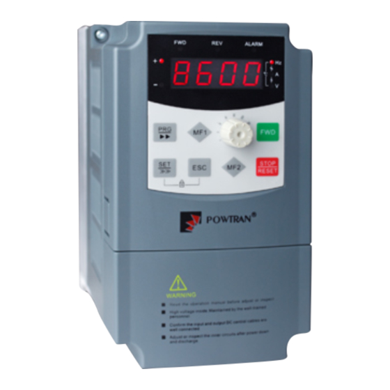
Thank you very much for purchasing PI8600 Family Frequency Inverters. This family is
designed based on the experience of POWTRAN Company in the professional manufacture and
sale of the products, and suitable for general-purpose load machine.
This product adopts the advanced sensorless vector control technology, combined with China
local frequency inverter application features to achieve high-performance V/F control (dead-time
compensation + auto-torque upgrade + Slip Compensation) and high-performance non-sense vector
control, and high-performance speed sensorless vector control.
This product adopts the advanced sensorless vector control technology, combined with the
application of inverter technology in China features to achieve high-performance V/F control
(dead-time compensation + auto-torque upgrade + Slip Compensation) and high-performance non-
sense vector control, and high-performance speed sensorless vector control.
This User‟s Manual includes PI8600, the general purpose control F and G series.
F: FLOW LOAD
G: GENERAL LOAD
Please contact the local dealers or directly contact our company.
Please keep this user‟s manual in good condition, for it will be helpful to the repair,
maintenance, and applications in the future.
For information about other product, please visit our website: http://www.powtran.com.
Foreword
Advertisement
Table of Contents

Related Manuals for Powtran PI8600 F Series


Summary of Contents for Powtran PI8600 F Series
- Page 1 Foreword Thank you very much for purchasing PI8600 Family Frequency Inverters. This family is designed based on the experience of POWTRAN Company in the professional manufacture and sale of the products, and suitable for general-purpose load machine. This product adopts the advanced sensorless vector control technology, combined with China...
-
Page 2: Table Of Contents
Directory Foreword ......................... 1 Section I Inspection &Safety Precautions ............. 1 Section II Installtion &Standby Circuit ..............3 Section III Operation Keyboard ................8 Section IV Test Running ..................16 Section V Parameter Function Table ..............18 5-1、 ..............18 Functional parameter list 5-2、... -
Page 3: Foreword
Section I Inspection &Safety Precautions POWTRAN PI8000 frequency inverters have been tested and inspected before leaving the manufacturer. Before unpacking the product, please check if its package is damaged due to careless transportation, and if the specifications and type of the product complies with the order. Please contact the supplier of POWTRAN products if any problems are found. - Page 4 ※ Powtran inverter is generally applied to 3 phase AC asynchronism motors. ※ Powtran inverter is applied to the admisive occasion, the occasion where is not admissive may lead to fire, electric shock, explosion and so on. ※ If the inverter seizes up when it is applied to the equipment which may lead danger (e.g. lift tools of transportation, aviation system, saftety equipment, etc), it should be managed carefully.
-
Page 5: Section Ii Installtion &Standby Circuit
Section II Installtion &Standby Circuit 2-1. Conditions for Use Ambient temperature -10℃~40℃. Avoid electromagnetic interference and keep the unit away from the interference source. Prevent dropping water, steam, dust, powder, cotton fiber or fine metal powder from entering it. Prevent oil, salt and corrosive gas from entering it. Avoid vibration. - Page 6 Section II Installtion & Standby Circuit 2-3-1. PI8600 Diagram ALARM ° C STOP/RESET ALARM R232 R485 跳线端子 PICOM RS485/RS232...
- Page 7 Section II Installtion & Standby Circuit 2-4. Main Circuit Terminals (G Series) 2-4-1. PI8600 Main Circuit Terminals 1.Main Circuit Terminals 2-4-2. Terminal Function Terminal Description Functions R/L1 Power input for frequency inverter Connected to 3-phase power, S/L2 Grounding point Grounded to the earth U,V,W Power output for frequency inverter Connected to 3-phase motor...
- Page 8 Section II Installtion & Standby Circuit o02/o03 can set input voltage/ current arrange. o08/o09 Set the input signal corresponding to set value. JP1 1-2: 0~+20mA . JP1 2-3: 0~+10VDC. Multifunction Analog output signal 1 o15 set analog output analog functions. o17/o18 set the output signal arrange.
- Page 9 Section II Installtion & Standby Circuit 2-5-2. Control circuit terminal 8KMCB Control circuit terminal 2-6. Connection Precautions Don‟t install power factor capacitance or resistance-capacitance absorbing device between ※ the output terminals U, V, W of the frequency inverter. ※ To disassemble or replace the motor, the input power supply must be turned off for the frequency inverter.
-
Page 10: Section Iii Operation Keyboard
Section III Operation Keyboard 3-1. Operating keyboard 3-1-1. JP6E8600 specification and function description(Standard) Monitor Select 1 Numerical Display Forward Indication Light Reverse Lndication Light Alarm Indication Data Unit Prompt Light * ON : forward indication * display the corresponding values of the * ON :... - Page 11 Section III Operation Keyboard 3-1-2. JP3E8600 keyboard specification and function description (Optional) Forward Indication Light Reverse Lndication Light Alarm Indication Data Unit Prompt Light * ON : forward indication * ON : reverse indication Light *composed of three indication * OFF : not forward indication * OFF :...
- Page 12 Section III Operation Keyboard 3-2. Example for parameters set 3-2-1. F01 keyboard set the frequency from 50.00Hz to 25.00Hz. 1. Under monitoring status, press into parameter group to query status; 2. Through potentiometerSwitch to F00-63 Basic FG; 3. Press , or ENTER, enter into F00-63 Basic FG parameter group to query status; 4.
- Page 13 Section III Operation Keyboard 3-2-2. parameter upload to the keyboard Parameter Item Description No function System parameter upload to the memory area1 in the keyboard System parameter upload to the memory area2 in the keyboard y01 parameter upload to the keyboard System parameter upload to the memory area3 in the keyboard System parameter upload to the memory area4 in the keyboard Clear memory area in the keyboard 1, 2, 3, 4...
- Page 14 Section III Operation Keyboard 3-2-3. Reset system parameters Parameter Item Description No function Memory area 1 in the keyboard to reset system parameter Memory area 2 in the keyboard to reset system parameter y00 Reset system parameters Memory area 3 in the keyboard to reset system parameter Memory area 4 in the keyboard 1to reset system parameter Use the factory setting reset system parameter Example 1: memory area3 in the keyboard 1 to reset system parameter...
- Page 15 Section III Operation Keyboard Example 2 Clear memory area 1, 2, 3, 4 in the keyboard 1. Under monitoring status, press into parameter group to check status 2. Through potentiometerSwitch to y00-23 System FG; 3. Press , enter into y00-23 System FG parameter group to check status; 4.
- Page 16 Section III Operation Keyboard 3-2-4. F02 the main set mode of set frequency is set to 4, keyboard potentiometer setting ! 1. Under monitoring status, Through potentiometer adjust the frequency, the resolution ratio potentiometer is 0.05Hz. 2. Range of set frequency can be set with the following parameters: Parameter item Description Inverter output maximum frequency allowed...
- Page 17 Section III Operation Keyboard 3-2-5. F02 the main set mode of set frequency is set to 2, AI2 external analog given. 1. Under monitoring status, Through external analog input terminal Al2 adjust the frequency, the resolution ratio is 0.01Hz. 2. Set the frequency range can be set with the following parameters: Parameter Item Description Inverter speed adjustment‟s allowed maximum...
-
Page 18: Section Iv Test Running
Section IV Test Running ● Failure occurred when test running, Please take reference of fault diagnosis in 6-1 to get rid of the breakdown. ● Inverter parameters have a strong adaptive ability, in general b11 = 1 calculation of electrical parameters with the name plate, on this basis, a little manual adjustment can get you high- performance vector control. - Page 19 Section IV Test Running sensor vector Control control sensorless vector control According to parameter adjust speed loopC01-C07、 setting F06 V / F boost Turned around differential gain、 mode regulate motor parameters adjust speed loopC01-C07、 Set F07 torque Turned around differential Upper torque boost value gain C09-C12、regulate...
-
Page 20: Section V Parameter Function Table
Section V Parameter Function Table Notice: ★mean that the factory setting value of the parameter is according to the power and model.The exact value is referred to the Parameter Function Table.Change limited mean that whether it can be modified while running. 8000 Slant font means PI8600 do not have such function. - Page 21 Section V Parameter Function Table voltage The output voltage The real output voltage Motor real speed Motor real running speed The total running time for Total running time every time Test the temperature of IGBT IGBT temperature℃ in the frequency PID Adjust run-time values of PID set point the percentage of a given...
- Page 22 Section V Parameter Function Table Multi-segment digital voltage setting Digital Pulse Setting Keyboard setting frequency or RS485 AI1 the external analog 8000 setting AI2 the external analog setting AI3 the external analog Auxiliary setting mode of 8000 setting frequency Keyboard potentiometer setting Multi-segment digital voltage setting...
- Page 23 Section V Parameter Function Table powerV/Fcurve Power of 2 power V/F curve Define mode V/Fcurve Close automatic torque boost 10 bit Automatic torqueboost VF mode 0 speed no Output 100 bit VF mode keep 0 speed Torque boost value 0.0~30.0% Torque boost cut-off 15.00 0.00~maximum frequency...
- Page 24 Section V Parameter Function Table Scurve start time at the 0.0~50.0 acceleration step Scurve stop time at the 0.0~50.0 acceleration step Scurve start time at the 0.0~50.0 deceleration step Scurve stop time at the 0.0~50.0 deceleration step Slip compensation V/F control slip invalid compensation Slip compensation valid...
- Page 25 Section V Parameter Function Table deceleration time before Lower frequency~upper Jog frequency setting 6.00 frequency 0.00 Skip frequency1 limit Skip frequency 1 limit Skip frequency 1 upper Skip frequency 1 upper 0.00 Skip frequency2 limit Skip frequency 2 limit 0.00 Skip frequency 2 upper Skip frequency 2 upper 0.00...
- Page 26 Section V Parameter Function Table potentiometer giving Adjustment of Multi steps digital voltage giving No adjustment of deceleration time AI1 adjustment of the external analog 8000 giving AI2 adjustment of the external analog giving 10 bit AI3 adjustment of the external analog 8000 giving...
- Page 27 Section V Parameter Function Table Over /less voltage stall protection Overvoltage stall 110%~140%(Standard bus voltage) protection voltage Invalid Valid Auto stabilize voltage Valid, useless for deceleration Invalid Dynamic braking option Security type General type Hysteresis voltage 0~10% 110%~140%(Standard bus Dynamic braking voltage voltage) 60%~75%(Standard DC bus Less voltage level...
- Page 28 Section V Parameter Function Table N torque inspection Warning and running Over torque inspected Warning and decelerating action stop Warning and free stopping ★ Over torque grade 10~250 Over torque inspection 0.0~60.0 time Electronic thermal relay protection selection Electronic thermal ★...
- Page 29 Section V Parameter Function Table 1~250: late inspection Auto clear to zero after power on Total running time Continue to accumulate setting running time after power hour Unit of total running time Motor output speed 0.1~1000.0 100.0 adjustment Adjustment of motor 0.1~1000.0 100.0 output power...
- Page 30 Section V Parameter Function Table Adjustment of Potentiometer giving Adjustment of multisteps digital voltage DN N adjustment of speed ratio AI1 adjustment of the 8000 external analog giving AI2 adjustment of the external analog giving 1000bit AI3 adjustment of the external analog 8000 giving...
- Page 31 Section V Parameter Function Table UP / DN adjusted value reset keyboard potentiometer setting value reset Potentiometer X1 0~100.00 0.00 Potentiometer X2 0~100.00 100.00 The value of keyboard 0.0~100.00 potentiometer set Keyboard potentiometer X1 corresponding value -100.00~100.00 0.00 Keyboard potentiometer X2 corresponding value -100.00~100.00 100.00...
- Page 32 Section V Parameter Function Table 5-1-5.IO Function System:o00-o68(0x0200-0x0244) Factory Change Reference Code Description / LCD Setting Range Setting Limited page 8000 AI1 nput X1 8000 AI1input X2 AI2input X1 0~100.0 AI2input X2 0~100.0 100.0 8000 AI3 input X1 0~100.0 8000 AI3 input X2 0~100.0 100.0...
- Page 33 Section V Parameter Function Table Actual value of torque DA1 adjustment of 0.0~200.0 lower limit output DA1 adjustment of upper 0.0~200.0 100.0 limit of output DA2 adjustment of 0.0~200.0 lower limit output DA2 adjustment of 0.0~200.0 100.0 upper limit output No function Fault warning Over current inspection...
- Page 34 Section V Parameter Function Table period completed Speed tricking mode inspecition N command running state REV running from inverter command Deceleration running Acceleration running Arrival of high pressure Arrival of low pressure Arrival of inverter rate current Arrival of motor rate current Arrival of input frequency lower limitation...
- Page 35 Section V Parameter Function Table Two - ware running control 1 Two - ware running control 2 Three - ware running 1bit control 1 Three - ware running Termianl control 0000 control 2 mode Oneshot running control 1 Oneshot running control 2 Power on terminal running command invalid 10bit...
- Page 36 Section V Parameter Function Table way 1 Frequency setting assist way 2 Frequency setting assist way 3 MSS timing running 1 MSS timing running 2 MSS timing running 3 Running control mode switch 1 Running control mode switch 2 Running control mode switch 3 FWD torque upper limit switch 1...
- Page 37 Section V Parameter Function Table Automatic program running function cancel Automatic program running stop Program running start mode Program running stop mode Pulse counter clearance Pulse counter input Preset counter value loading Upper counter value loading Out fault signal input (level) 1 pump start 1 pump stop...
- Page 38 Section V Parameter Function Table External fault signal input (edge) Polarity of input and 0000~F7FF 0000 output terminals Input response time 0 0.001~30.000 0.005 Input response time 1 0.001~30.000 0.005 Response time of input 0~07FF terminal selection Cycle counting operation 1 bit Single cycle counting operation...
- Page 39 Section V Parameter Function Table Actual frequency Actual current Output voltage DC bus voltage IGBT temperature Output frequency Output rpm Torque actual value SPA pulse output rate 1~1000 SPB pulse output rate 1~1000 Boot time 1 bit Limit time 1 Running timing configuration 0000...
- Page 40 Section V Parameter Function Table configuration Terminal control Program running start 0~15 segment Program running end 0~15 segment Output signal valid time Output signal valid time 1000 20ms Output signal valid time 100ms Output signal valid time 500ms Single-cycle Continuous cycle One-cycle command running...
- Page 41 Section V Parameter Function Table 10 Segment speed setting Lower frequency upper 30.00 frequency 11 Segment speed setting Lower frequency upper 33.00 frequency 12 Segment speed setting Lower frequency upper 36.00 frequency 13 Segment speed Lower frequency ~ upper 39.00 setting 13X frequency 14 Segment speed...
- Page 42 Section V Parameter Function Table time dt6 7 Segment acceleration 0.0~3200.0 10.0 time at7 7 Segment deceleration 0.0~3200.0 10.0 time dt7 1 Segment deceleration 0.0~3200.0 10.0 time dt1 Running direction:forward 1 bit Running direction: reverse Running time: *seconds 1Segment speed Running time: *munites configuration word 10 bit...
- Page 43 Section V Parameter Function Table Current running time 0~0x7 100 bit segment Current digit voltage 0~0x7 1000bit segment 5-1-7.V/Fcurve Group:U00-U15(0x0400-0x040F) Factory Change Reference Code Description / LCD Setting Range Setting Limited page V/F setting frequency1 0.00~U02 5.00 V/F setting voltage 1 0~U03 V/F setting frequency2 U00~U04...
- Page 44 Section V Parameter Function Table 1000bit PID Output Limit 0~100 Set frequency by keyboard or RS485 AI1 external analogy 8000 giving AI2 external analogy giving Feedback signal AI3 external analogy selection 8000 giving Keyboard potentiometer giving muti-step digital voltage giving Digital pulse set Set frequency by keyboard or RS485...
- Page 45 Section V Parameter Function Table Setting Limited page General Pump Injection machine Textile machine Hoist machine Kowtow machine belt conveyor Load type Variable frequency power Multi-pumps constant pressure water supply Reserved Reserved Torque control Voltage regulation power Current regulation power Extruding machine Starting pressure 0.0~100.0...
- Page 46 Section V Parameter Function Table mode Single circle The current timing step 1000bit Timing shift alternation 0.0~3200.0 time Electromagnetic switch 0.000~10.000 0.500 action delay Pumps shift judging 0~9999 time All pumps slow down stop Variable frequency Stop 1 bit pump stop mode Free stop Water...
- Page 47 Section V Parameter Function Table Pump 3 invalid Pump3variable frequency 100bit to control pump Pump3soft starts to control pump Pump 4 invalid Pump4variable frequency 1000bit to control pump Pump4soft starts to control pump Pump 1 stop Pump 1 run in variable 1 bit frequency Pump 1 run in working...
- Page 48 Section V Parameter Function Table Pump 4soft-stop command 1 Pump 4soft-start command 2 User parameter 0 0~9999 User parameter 1 0~9999 User parameter 2 0~9999 User parameter 3 0~9999 User parameter 4 0~9999 User parameter 5 0~9999 User parameter 6 0~9999 User parameter 7 0~9999...
- Page 49 Section V Parameter Function Table or RS485 setting mode mode AI1 external analogy 8000 giving AI2 external analogygiving AI3 external 8000 analogygiving Keypad potentiometer giving Multi-step digital voltage giving Digital pulse set Direction uncontrolled 10bit direction Direction controlled Set by keyboard or RS485 AI1 external 8000...
- Page 50 Section V Parameter Function Table analog setting AI3 external 8000 analog setting Keyboard potentiometer setting Multi-segment digital voltage setting Digital pulse detting C19 unit bit setting 10bit selection S00 detting grequency Upper speed 0.00~Max frequency 50.00 Torque acceleration 0.0~200.0 time Torque deceleration 0.0~200.0 time...
- Page 51 Section V Parameter Function Table 5-1-11.Motor Parameter:b00-b22(0x0800-0x0816) Factory Change Reference Code Description / LCD Setting Range Setting Limited page Motor 1 rated frequency 0.00~Max frequency 50.00 ★ Motor 1 rated current y09*(50%~100%) ★ Motor 1 rated voltage 100~1140 Motor 1 pole-pairs Motor 1 rated speed 500~5000 1480...
- Page 52 Section V Parameter Function Table Motor 2 mutual ★ 0.0~3200.0 inductance 5-1-12.System Parameter:y00-y17(0x0900-0x0911) Factory Change Reference Code Description / LCD Setting Range Setting Limited page No action Reset system parameter with keyboard storage1 Reset system parameter with keyboard storage 2 Reset system parameter Reset system parameter with keyboard storage 3...
-
Page 53: Functional Parameter Specification
Section V Parameter Function Table Input Family Product oltage code serial grade 1 Software version Product date--year YYYY MMDD Product date-month/day 0~9999 range User decode input Displ Record password wrongly input times info 0~9999 range No password or User password key-in decode input is deco Displ... -
Page 54: Monitor Function:s00-S15(0X0B00-0X0B0F)
Section V Parameter Function Table Motor parameter group Motor parameter setting Parameter reset, fault query, product System function group information, parameter protection 5-2-2.Monitor Function:S00-S15(0x0B00-0x0B0F) Factory Change Code Description / LCD Setting Range Unit Setting Limited Current inverter real setting Setting frequency frequency Current inverter real output Real frequency... -
Page 55: Basic Function Group:f00-F50(0X0000-0X0032)
Section V Parameter Function Table Excitation heft set value Motor set excitation heft percentage Excitation heft actual Motor actual excitation heft value percentage Torque heft Set value Motor set torque percentage Torque heft actual value Motor actual torque heft percentage 5-2-3.Basic Function Group:F00-F50(0x0000-0x0032) Factory Change... - Page 56 Section V Parameter Function Table Multi-segment digital voltage setting Digital Pulse Setting The main mode of the frequency running frequency: 0 : keyboard setting frequency or RS485 change F01 keyboard setting frequency Multi-digital voltage terminal effective exchange, change F01keyboard setting value 1 : AI1 the external analog setting Given the external analog0~10V,-10V~+10V,0~20mA.For detail please read the o group parameter.
- Page 57 Section V Parameter Function Table After multi-digital voltage terminal effective switch, change F01keyboard setting. 1 : AI1 the external analog setting Given the external analog0~10V,-10V~+10V,0~20mA.For detail please read the o group parameter. 2 : AI2 the external analog setting Given the external analog 0~10V, 0~20mA.For detail please read the o group parameter. 3 : AI3 the external analog setting Given the external analog 0~10V, 0~20mA.For detail please read the o group parameter.
- Page 58 Section V Parameter Function Table Minimum{main,auxiliary} 6 Main given and auxiliary given set frequency relations: Main given value and auxiliary given value can be added up,subtracted, multiplied,maximum, minimum calculation. O group parameters can be adjusted to coordinate the main given and auxiliary given proportion, to meet the requirements of the system fine-tuning and bias.
- Page 59 Section V Parameter Function Table 0 : keyboard+Rs485/CAN Control 1 : keyboard+Terminal+Rs485/CAN Control control terminal, edge trigger, falling edge of the implementation of the Forward command FWD / Reverse command REV, rising edge of the implementation of the STOP command 2 : Rs485/CAN Control Under this function, only free stop funciont is valid under the keyboard control, other operation control is invalid...
- Page 60 Section V Parameter Function Table parameters which affect automatic torque enhance : Actual value torque component S15 b06/b19 stator resistance F07 torque enhance value Automatic torque enhance value = actual value of torque component * stator resistance *torque enhance value. 100 bit: VF mode 0 speed maintain function 0 VF mode 0 Speed No Output: Output frequency is less than 0.5Hz, stop PWM output to reduce the switching loss.
- Page 61 Section V Parameter Function Table The percentage of the actual output voltage and the rated output voltage. Used to adjust the output voltage,output voltage=inverter rated output voltage*percentage of output voltage. 50.00 Maximum frequency 10.00~320.00 Inverter output maximum frequency allowed is also the setting basis of acceleration / deceleration time.
- Page 62 Section V Parameter Function Table inverter are great, the efficiency is decreased and the output capacity is reduced. At the same time, more serious radio interference is resulted and special attention must be paid for application where very low EMI is needed, and filter option can be used if necessary. Another problem for application of high carrier frequency is the increase of capacitance-leakage current.
- Page 63 Section V Parameter Function Table 1: automatic adjustment, random mode Load current >80% Carrier frequency = (F16-F17)~F16 Load current <60% Carrier frequency = F16~(F16+F17) Asynchronous space-vector Stepless & subsection Waveform generation synchronous space vector mode Two-phase optimization space vector PWM PWM wave produce mode 0: Asynchronous space-vector PWM 1: Stepless &...
- Page 64 Section V Parameter Function Table 1 : Slip compensation function is valid. Slip compensation value adjusted by the following parameters to ensure stable speed under load fluctuations and heavy load, C09 Low Slip Gain C10 Low Slip switching frequency C11 High-Speed Slip Gain Slip C12 high-speed switching frequency Minimum running 0.00~Maximum frequency...
- Page 65 Section V Parameter Function Table Stop and brake starting 0.00~ Max frequency 0.00 frequency Inverter slowing down to stop braking start frequency, stop the output PWM waveform to begin injection of DC current, the current size by the shutdown of DC braking current setting, braking time, braking time set by the downtime.
- Page 66 Section V Parameter Function Table 0 : Deceleration to stop Mode converter according to parameters set by the deceleration time to set the deceleration mode to slow down to the lowest frequencies to stop. 1 : Free stop mode Inverter receive "stop" command immediately stop output, according to the load inertia, motor free-run to stop.
- Page 67 Section V Parameter Function Table Skip frequency 2 upper Skip frequency 2 upper 0.00 Skip frequency3 limit Skip frequency 3 limit 0.00 0.00 Skip frequency 3 upper Skip frequency 3 upper During running, to skip resonance produced by the immanent resonance point in the machine systems, skip mode can do this.
- Page 68 Section V Parameter Function Table direction decided by terminal and keyboard command. 1: Prior command: positive or negative value of analog input, setting frequency positive value let motor forward running, setting negative value let motor reverse running. 100 bit: motor reverse allow. For some producing equipment, the reverse may lead to damage to the equipment, so this feature can be used to prevent motor reverse, Inverter default forbidden reverse.
- Page 69 Section V Parameter Function Table external analog giving AI3 adjustment of the 8000 external analog giving Adjustment of keyboard potentiometer giving Adjustment of Multi steps digital voltage giving Acceleration time:*s Acceleration time:*min 100 bit Acceleration time:*h Acceleration time:*day Deceleration time:*s Deceleration time:*min 1000bit Deceleration time:*h...
- Page 70 Section V Parameter Function Table *Min 3200.0 Min 3200.0 H *Day 3200.0 Day Running direction: forward 1 bit Running direction: reverse Running Running time: *s configuration 0000 Running time: *min word 10 bit Running time: *h Running time: *day Unit adjustment of actual running time.It is only valid on program running. 1 bit: Program running on multi-speed running period, Set bit to running direction of “0”step speed.
-
Page 71: User Function Group:a00-A55(0X0100-0X0137)
Section V Parameter Function Table output voltage by the load condition. In the process of acceleration and deceleration is not to make such calculations. Power-saving function is by lowering the output voltage and improve power factor to achieve the purpose of saving energy, this parameter determines the minimum value of reducing of output voltage;... - Page 72 Section V Parameter Function Table DC voltage time output frequency time 0 : This function invalid 1 : This function valid When the inverter deceleration, as the motor load inertia, motor will produce feedback voltage to inverter inside, which will increase DC bus voltage and surpass max voltage. When you choose Over /less voltage stall protection and it is valid, Inverter detects DC side voltage, if the voltage is too high, the inverter to stop deceleration (the output frequency remains unchanged), until the DC side voltage is below the set value, the inverter will re-implement the...
- Page 73 Section V Parameter Function Table energy-braking function. Users can select inverter models with a braking function to apply this feature. 60%~75%(Standard DC bus Less voltage level voltage) The definition of allowed the lower limit voltage of normal working inverter DC side .For some low power occasions, inverter less voltage value can be appropriately put down in order to ensure the inverter normal working.
- Page 74 Section V Parameter Function Table If this value set is too large, the load feedback energy is small, then inverter can not compensate for voltage dropping in DC. If this value set is too small and there is large energy feedback from load, the excessive energy compensation may cause inverter over-voltage fault.
- Page 75 Section V Parameter Function Table Warning and free stopping ★ Over torque grade 10~250 Over torque inspection time 0.0~60.0 Motor output current surpass value A21 set, Over torque inspection will be force and the system will show OL2 fault. Series Over torque inspection class Parameter Electronic thermal relay...
- Page 76 Section V Parameter Function Table After 10 s of meeting fault, inverter will not recover fault reset function. Fault reset time 0.5~20.0 Setting interval of fault reset time. When inverter met fault and stopped outputting, and when it inspected without fault time is longer than fault reset time, Inverter will automatically implement fault reset.
- Page 77 Section V Parameter Function Table 8,E,2 for RTU 8,O,2 for RTU Seeing attachment for detailed specification. N warning for communication fault Warning and running Communications troubleshooting Warning and decelerating stop Warning and free stopping 0: N inspection Delay inspection time 1~250: late inspection When communication time between interface A or B surpassed A32 delay inspection time, the system will warn according to A31 setting.
- Page 78 Section V Parameter Function Table 2 2 2 2 2 2 2 2 7 6 5 4 3 2 1 0 STOP Potentiometer Key SET+ESC in Keyboard can activate and cancel keyboard lock function. To lock which key will be decided by corresponding parameter : Set 0~10 bit Keyboard locked state Unlock FWD key...
- Page 79 Section V Parameter Function Table Valid adjustment 1 bit: UP/DN control saving state after power down 0: Power down to save 1: Power down to clear 10 bit: UP/DN control saving after stopping 0: Keeping after stopping 1: Stop command to clear saving 2: Cleared at the end of stopping 100 bit: UP/DN control direction of adjustment.
- Page 80 Section V Parameter Function Table 1 bit: UP acceleration mode 0: Fix speed acceleration, according to A41 fix speed: To increase frequency every 200ms. 1: Fix times acceleration, according to fix times: To increase frequency every triggering. 10 bit: DN deceleration mode 0: Fix speed deceleration, according to A42 fix speed: To reduce frequency every 200ms.
- Page 81 Section V Parameter Function Table stopping key MF is defined as FWD running key MF is defined as REV running key MF is defined as forward JOG function key. MF is defined as reverse JOG function key. MF is defined as JOG function key.
- Page 82 Section V Parameter Function Table A38 ~ A42 decision. UP/Dn function effectively set A38 kilobit=1. 9: Mfisdefined as Down function key Keybaord effectively anytime ,frequency inverter Down control ,parameter can be control A38~A42 decided. UP/DN Functions effectively to set A38 kilobit=1. 10:Mfis defined UP/DN regulate clearance A40 UP /Dn regulate clearance,Electrical level trigger.
-
Page 83: Io Function System:o00-O68(0X0200-0X0244)
Section V Parameter Function Table 1000bit Reserved 1 bit: Saving state of potentiometer after power down . 0: Saving after power down. 1: Clearing saving after power down. 10 bit: Keeping potentiometer set after stopping. 0: Keeping after stopping 1: To clear saving after stop command. 2: To cear saving at end of stopping. - Page 84 Section V Parameter Function Table 8000 AI1input X2 AI2input X1 0~100.0 AI2input X2 0~100.0 100.0 8000 AI3 input X1 0~100.0 8000 AI3 input X2 0~100.0 100.0 AI1 input X1 corresponding 8000 value Y1 AI1 input X2 corresponding 8000 value Y2 AI2 input X1 corresponding -100.0~100.0 Value Y1...
- Page 85 Section V Parameter Function Table X1=0% , Y1=20% potentiometer 0V corresponding set value: f=Max frequency*Y1=10.00Hz X2=50%, Y2=50% potentiometer 5V corresponding set value: f=Max frequency*Y2=25.00Hz 100% ( X2,Y2) Y2=50% Y1=20% (X1,Y1) AI1,AI2,AI3 X1=0% X2=50% 100% X1=0%,Y1=-100% potentiometer 0V corresponding set frequency:f=Max frequency*Y1=- 50.00Hz X2=100%,Y2=100%potentiometer 10V correspond set frequency:f=maximum frequency*Y2=50.00Hz...
- Page 86 Section V Parameter Function Table Output RPM Actual value of torque DA1 adjustment of lower 0.0~200.0 limit output DA1 adjustment of upper 0.0~200.0 100.0 limit of output DA2 adjustment of lower 0.0~200.0 8000 limit output DA2 adjustment of upper 0.0~200.0 100.0 8000 limit output...
- Page 87 Section V Parameter Function Table Caution: Every terminal has choice of voltage output and current output, the default setting is voltage output. When the voltage output is needed, please connect JP1/JP2 and DA1V/DA2V(seeing the panel); When the current output is needed, please connect JP1/JP2 and DA1C/DA2C.
- Page 88 Section V Parameter Function Table Deceleration running Acceleration running Arrival of high pressure Arrival of low pressure Arrival of inverter rate current Arrival of motor rate current Arrival of input frequency lower limitation Arrival of current upper limitation Arrival of current lower limitation Time to reach limit time 1 Time to reach limit time 2...
- Page 89 Section V Parameter Function Table Arrival of FDT set frequency2 Arrive at frequency 2 FDT set Inspection Level Of FDT FDT frequency levels to meet the inspection Frequency conditions,o29~ o31 Arrival of preset counting Present counting value arrives at preset counting value value Arrival of counting value...
- Page 90 Section V Parameter Function Table output frequency FDT1=35Hz FDT2=30Hz time FDT frequency setting 1 arrived time FDT frequency setting 2 arrived time FDT frequency inspection level time ON means signal will react, OFF means signal will not react When the choice of output signal(o21~o24)is set as14, inverter output frequency arrives at or surpass FDT set frequency 1, the corresponding signal output terminal will react;...
- Page 91 Section V Parameter Function Table current percentage o32=120 o33=20 o34=3 current upper limitation time current lower limitation time time ON means signal will react, OFF means signal will not react Two - ware running control 1 Two - ware running control 2 Three - ware running 1bit...
- Page 92 Section V Parameter Function Table Down Low level Down edge edge Falling High level Falling edge edge Up edge Up edge High level Up edge Up edge 1 Two-ware running control 2 . RUN/ STOP FWD/ REV F05=1 or F05=4 F05=3 Command Falling...
- Page 93 Section V Parameter Function Table FWD/ STOP REV/ STOP F05=1;F05=4;F05=3 Command Current status STOP Keep STOP STOP Keep Keep STOP 5 One shot running control 2. RUN/ STOP FWD/ REV F05=1;F05=4;F05=3 Command Current status Low level STOP High level STOP STOP STOP 10 bit: Set the terminal status when power on...
- Page 94 Section V Parameter Function Table 8000 selection Multistage acceleration (DI7) input terminal function order 1 8000 selection Multistage acceleration (DI8) input terminal function order 2 8000 selection Multistage acceleration (AI1) input terminal function order 3 8000 selection (AI2) input terminal function Multi digital voltage 1 selection Multi digital voltage 2...
- Page 95 Section V Parameter Function Table REV torque upper limit switch 3 Torque speed switch Fault involution command FWD JOG order REV JOG order JOG order (as F35setting ) 36 Accelerate and decelerate prohibit order Motor 1、2 switch Free stop Up command Down command Automatic program running function cancel...
- Page 96 Section V Parameter Function Table 4 pump stop Manual rotate command Time water supply time interval reset to 0 Extruder acceleration deceleration direction Extruder acceleration deceleration permit Time limit 1 input Time limit 2 input Program running switch next step UP/DN regulate clearance 66 Keyboard potentiometer setting clearance...
- Page 97 Section V Parameter Function Table frequency setting main way 3 frequency setting assistant way 1 Combine frequency setting assist way frequency setting assistant way 2 switch.Detail F parameter system frequency setting assistant way 3 MSS timing running 1 Combine 8 step time setting.Detail H MSS timing running 2 parameter system MSS timing running 3...
- Page 98 Section V Parameter Function Table Auto-run feature programs canceled Cancel program running function. Automatic procedures to suspend Program running pause operation Program running start mode Program running start mode Program running stop mode Program running stop mode Edge trigger, frequency inverter pulse Pulse count clearance counter O53 clearance Edge-triggered, set the pulse counter input...
- Page 99 Section V Parameter Function Table Extruder acceleration deceleration DIx input terminal function slection, direction detail in o36-o46 Extruder acceleration deceleration DIx input terminal function slection, allow detail in o36-o46 Time limit 1 input DIx input time limit 1,, detail in o65,o67 Time limit 2 input DIx input time limit 2,, detail in o66,o68 Program switching to the next...
- Page 100 Section V Parameter Function Table Set 0~10 bit Polarity of input terminal o48 input terminal response time 0 o49 input terminal response time 1 2 2 2 10 9 8 Cycle counting operation 1 bit Single cycle counting operation reloading after the count value reaches maximum 10 bit count is cleared after the...
- Page 101 Section V Parameter Function Table 2 Output single valid time 100ms,when reach this value, keep output status valid 100ms. 3 Output single valid time 500ms,when reach this value, keep output status valid 500ms. Maximal pulse input 0.1~50.0 20.0 frequency This parameter define maximal pulse input frequency of analogy setting. This input signal frequency is high, so it should be set by multifunctional terminalDI6.
- Page 102 Section V Parameter Function Table 14 13 2 2 2 2 2 2 2 2 2 2 2 2 2 2 2 2 15 14 13 12 11 10 9 8 7 6 5 4 3 2 1 0 leave unused DI1~4 terminal status 0000~1111 8000...
-
Page 103: Multi-Speed Plc Group:h00-H55(0X0300-0X0337)
Section V Parameter Function Table Value No action No output Set frequency 0~Max frequency Actual frequency 0~Max frequency 0~200%, corresponding paramerter: S03 Actual current output current percentage 0~200%, correlation parameter: b02、b15 Output voltage motor rated voltage Bus voltage 0~1000V DC voltage IGBT temperature 0~100.0℃... - Page 104 Section V Parameter Function Table Deceleration and acceleration time decised by H26~H39 100 bit Time of acceleration and deceleration isdecided by terminal Running time decised by H18~H25 1000bit Running time decised by terminal 1 bit: Program running functions intelligent To use the program to run PLC functionality requires setting the bit to 1. Multi-segment speed run only need to set the corresponding multi-stage o36 ~ o46-speed switching can be used without the need to set this parameter.
- Page 105 Section V Parameter Function Table Do not use of multi - stage speed control terminal o 36 ~ o46 multi - speed instruction, You can use o36 ~ o46 switchover next function. The terminal control for single trigger, triggered once, program running to next paragraph, running time recalculated.Running time of arrival, Running based on the 0 paragraph speed.
- Page 106 Section V Parameter Function Table putput frequency 60Hz 50Hz 40Hz 30Hz 20Hz 10Hz time 10Hz program running STOP time Continuous circulation Eg3:Program is running in single cycle, According to Paragraph seventh of Speed mode output frequency 60Hz 50Hz 40Hz 30Hz 20Hz 10Hz time...
- Page 107 Section V Parameter Function Table output frequency X+Y=T3 F51=01 time at3' dt3' STOP Eg:100 bit=1 Set down to the initial segment 1000 bit=1 Running at the speed before the machine stopped. output frequency F51=10,11 time at1' dt1' STOP Note: at1' :at the time of segment 1 acceleration time;dt1' :at the time of segment 1 deceleration time;at3'at the time of segment 3 acceleration time;dt3'...
- Page 108 Section V Parameter Function Table 13 Segment speed setting Lower frequency ~ upper 39.00 frequency 14 Segment speed setting Lower frequency ~ upper 42.00 frequency 15 Segment speed setting Lower frequency ~ upper 45.00 frequency Set the frequency of program running and the running frequency of 7-segment speed respectively.
- Page 109 Section V Parameter Function Table 0 Segment running time T0 0.0~3200.0 1 Segment running time T1 0.0~3200.0 0.0~3200.0 2 Segment running time T2 3 Segment running time T3 0.0~3200.0 4 Segment running time T4 0.0~3200.0 5 Segment running time T5 0.0~3200.0 6 Segment running time T6 0.0~3200.0...
- Page 110 Section V Parameter Function Table Definite acceleration and deceleration time for multi-step speed: output frequency time Definition of multi-step speed acceleration/deceleration time Running direction:forward 1 bit Running direction: reverse Running time: *seconds 1Segment speed Running time: *munites configuration word 10 bit 2Segment speed Running time: *hours 0000...
- Page 111 Section V Parameter Function Table Running time 10 bit Range(e.g.H18~H25=3200.0) *seconds 3200.0 S 3200.0 Min *minutes *hours 3200.0 H *days 3200.0 Day 100 bit, 1000 bit : Unit of acc/deceleration time of multi-segment speed program running Acceleration /deceleration 1000 bit, 100bit Range(e.g.H26~H39=3200.0) time ×...
-
Page 112: V/Fcurve Group:u00-U15(0X0400-0X040F)
Section V Parameter Function Table 5-2-7.V/Fcurve Group:U00-U15(0x0400-0x040F) Factory Change Code Description / LCD Setting Range Unit Setting Limited V/F setting frequency1 0.00~U02 5.00 output voltage max output output frequency (0,0) F1 F2 F3 F4 F5 F6 F7 max frequency User-defined the first frequency value of V / F curve, corresponding to V1 V/F setting voltage 1 0~U03 User-defined the first voltage percentage of V / F curve, on the base of rated output voltage... -
Page 113: Pid Parameter:p00-P12(0X0500-0X050C)
Section V Parameter Function Table V/F setting frequency7 U10~U14 35.00 User-defined the seventh frequency value of V / F curve, corresponding to V7. V/F setting voltage 7 U11~U15 User-defined the seventh voltage percentage of V/F curve, on the base of rated output voltage 100% of frequency converter, corresponding to F7. - Page 114 Section V Parameter Function Table 3: Warning & Free stop: free stop after abnormity feedback signal . PID Output Limit 0~100 The parameter defines the limited range of the output when using PID control. Set frequency by keyboard or RS485 AI1 external analogy 8000 giving...
- Page 115 Section V Parameter Function Table The PID integral time determines the integral regulation speed,the regulation acts on the difference between PID feedback and setting value by PID regulator. When the difference between PID feedback and setting value is 100% , integral regulator PID regulator ouput=(P01*F12*12.5%)Hz.(single direction PIDregulation,ignores proportion and differential effect).
-
Page 116: Expanding Parameters:e00-E23(0X0600-0X0617)
Section V Parameter Function Table PID regulation fault. PID display range 0.00~100.00 1.00 A09 PID set value=PID set value(%)*P12 A10 PID feedback value=PID feedback value(%)*P12 If PID feedback 10V corresponding 4.0Mpa pressure, if need A09, A10 to display actual value, only need to set P12 = 0.04. 5-2-9.Expanding Parameters:E00-E23(0x0600-0x0617) Factory Change... - Page 117 Section V Parameter Function Table stop frequency and the start pressure control function is invalid E01, E02, E03,E04 mix are used to control system energy-saving operation and continuous pressure regulation in water supply systems : For example Given pressure = 50% Starting pressure deviation =10%, starting pressure = given pressure - starting pressure deviation=40% Stopping frequency= 5Hz...
- Page 118 Section V Parameter Function Table 0 Cycle mode Timing the operation time from the starting to the set watter supply time,the inverter will automatically move to the next period of time set, after the end of a loop, it will automatically re-start from the first paragraph 0, then cycle to run.
- Page 119 Section V Parameter Function Table Electromagnetic switch action delay time when set up a pump (drive motor) to switch from variable frequency to industry frequency,or from industry frequency to variable frequency. This is to avoid inverter output frequency meet with the AC power supply and occur short circuit caused because electromagnetic switch action too slow.
- Page 120 Section V Parameter Function Table pump and soft start pump under frequency keep running. Stop power frequency pump,you need to use o36~o46parking command or keyboard input terminal free multi - function keys MF1, MF2 set to 2 : Free Parking function. 2 Free stop, all pumps free stop After free stop,E11 1000bit pump reset according to the order start and stop,but reorder according to E12 multi - pumps configuration.
- Page 121 Section V Parameter Function Table pump Pump 3 invalid Pump3variable frequency 100bit to control pump Pump3soft starts to control pump Pump 4 invalid Pump4variable frequency 1000bit to control pump Pump4soft starts to control pump Under Multi-pump control mode, set the control mode of each pump. Pump 1 stop Pump 1 run in variable 1 bit...
-
Page 122: Speed-Loop Parameter:c00-C31(0X0700-0X071F)
Section V Parameter Function Table Pump 3soft-stop command 1 Pump 3soft-start command 2 Pump 4soft-no command Pump 4soft-stop command 1 1000bit Pump 4soft-start command 2 Under Multi-pump control mode, set the control mode of each pump. User parameter 0 0~9999 User parameter 1 0~9999 User parameter 2... - Page 123 Section V Parameter Function Table It defines low-speed loop switching frequency, the parameter and switching frequency at high-speed optimize Speed-loop PID parameter. Speed loop high speed Ti 0.01~100.00 0.50 It defines integration time of High-speed section of the speed loop.Range is 0.01~100.00s.integration time too large and unresponsive, external interference control variation becomes weak ;...
- Page 124 Section V Parameter Function Table analogy 8000 giving AI2 external analogygiving AI3 external 8000 analogygiving Keypad potentiometer giving Multi-step digital voltage giving Digital pulse set Direction uncontrolled 10bit direction Direction controlled Set by keyboard or RS485 AI1 external 8000 analogy AI2 external analogy giving Setting...
- Page 125 Section V Parameter Function Table Digital Pulse Setting As per digital pulse setting While the unit digit of C15,C16 is 1~6, the upper torque of C13,C14 is for checking. C15 10 bit: Direction Control C16 10 bit: Direction Control 0: No control Direction Direction is controlled by terminal or keyboard 1:Control Direction Setting value of forward torque >...
- Page 126 Section V Parameter Function Table Upper speed 0.00~Max frequency 50.00 While torque control, setting upper speed C19 1 bit: Separate setting mode keyboard or RS485 setting As per C20 setting 8000 AI1 external analog setting AI2 external analog setting As per AI2 external analog setting 8000 8000 AI3 external analog setting...
-
Page 127: Motor Parameter:b00-B22(0X0800-0X0816)
Section V Parameter Function Table Warning and keeping running Warning and deceleration stop Warning and free stop. Set the brake method when detect PG break. 0: NO PG break protection 1: Warning and keeping running 2: Warning and deceleration stop. 3:... - Page 128 Section V Parameter Function Table To assure the control performance, please match the right motor as per the inverter‟s standard, Motor rated currents limited between 30%~120% of inverter rated current.The rated current can be set, but can‟t be more than the rated current of the inverter. The parameter Confirms the OL protection capability of the motor and energy-saving running.
- Page 129 Section V Parameter Function Table Keyboard figures area show "CAL1", inverter without output. Keyboard figures area show "CAL2", inverter with output, static state. Keyboard figures area show "-END": measuring ends. Keyboard figures area show "E. CAL": the measurement process errors. Process can be measured through the STOP key to stop.
-
Page 130: System Parameter:y00-Y17(0X0900-0X0911)
Section V Parameter Function Table 5-2-12.System Parameter:y00-y17(0x0900-0x0911) Factory Change Code Description / LCD Setting Range Unit Setting Limited No action Reset system parameter with keyboard storage1 Reset system parameter with keyboard storage 2 Reset system parameter Reset system parameter with keyboard storage 3 Reset system parameter with keyboard storage 4 Reset system parameter... - Page 131 Section V Parameter Function Table Fault record 3 Fault record 4 Fault record 5 These parameters register fault which happen in the last several times, and can inquire about the value of monitor object at the time of fault by „PRG‟ and “plus or minus” key. The monitor object of fault state: 0 : Fault type The fault code is expressed as following:...
- Page 132 Section V Parameter Function Table The actual output current at the time of fault 4 : Output DC voltage at the time of fault The actual output voltage at the time of fault 5 : Running state at the time of fault The running state at the time of fault LEDdisplay is below: The first LED...
- Page 133 Section V Parameter Function Table wrongly input times info In the state of locked parameter,LED displays the times of error input. There are three input limit,if input is wrong in continuous three times , the systems will prohibit input of the password . It can prevent testing password in an illegal way, and need restart the machine to input again.Once the input is right in any time during three times input limit, the parameter is unlocked 0~9999...
-
Page 134: Section Vi Fault Diagnosis & Solutions
Section VI Fault Diagnosis & Solutions 6-1. Problems and solutions Problems Possible Causes Solutions Running control mode setting Keyboard Check F05 is wrong can not control Frequency setting is wrong Check F03、F04 Potentiom Control mode setting is wrong Check F05 eter can‟t regulate Frequency setting is wrong... - Page 135 Section VI Fault Diagnosis & Solutions Modify b04、b14 in case of the motor overload Inappropriate parameter is set allowed Check voltage is right or not. Power voltage exceeds the Frequency inverter rated voltage setting is Y limit or N. Over voltage Too fast deceleration Modify F10.
-
Page 136: Section Vii Standard Specifications
Section VII Standard Specifications 7-1. Specification 7-1-1. PI8600 Specification Light Load Standard Load Structure Inverter type item Single phase voltage 220V 50/60Hz PI8600●●●□1 0.75 PI8600●●●□1 0.75 PI8600●●●□1 Table of rated current for different specifications 7-1-2. 220V Votage 1Ф Power (kW) Current (A) 0.75... - Page 137 Section VII Standard Specifications 7-2. Standard specification Items Specifications Single-phase 200~240V, 50/60Hz Voltage and frequency Power Allowable Fluctuation range voltage: ± 10% frequency: ± 5% high performance vector control inverter based on 32 bit Control system G/F type: 0.00~600.0Hz, maxmum frequency can be set Output frequency between 10.00 and 600.0Hz control method...
- Page 138 Section VII Standard Specifications constant speed, the program running. Built-in PID regulator brake current flow in the premise, DC brake however, to ensure adequate braking torque. Overvoltage protection, undervoltage protection, over- current protection , overload protection,over-temperature protection, over the loss of speed protection, over-voltage Inverter protection stall protection , phase protection (optional) , external fault , communication error , PID feedback signal...
- Page 139 Section VII Standard Specifications type of failure time when failure occurrs, set frequency, output frequency, output voltage, output current, running state, running time, IGBT temperature. Commu- Rs485 port and an optional keyboard completely isolated Double RS485 port RS485 communication module. nication At most 16 segments can be set(use multi-functional 16-segment speed...
- Page 140 Section VII Standard Specifications 7-3. Shape Size 7-3-1. PI8600 Series ALARM ° C STOP RESET WARNING Read the operation manual before adjust or inspect. High voltage inside.Maintained by the well-trained personnel. Confirm the input and output dc control cables are well connected.
- Page 141 Section VII Standard Specifications Keyboard Size 7-3-2. JP6C8000 Size:...
-
Page 142: Section Viii Inspection & Maintenance
Section VIII Inspection & Maintenance 8-1. Inspection and Maintenance Under normal working conditions, in addition to daily inspection, the frequency converter should be subject to regular inspection (for example inspection for overhaul or as specified but at an interval of six months at most). Please refe r to the following table in order to prevent faults. Check time Check point... - Page 143 第八章 保养与检修 module is damaged. If measuring is necessary, the user should note that much different results will be gained possibly if the measuring is performed with different instruments. It is recommended that the input voltage be measured with pointer-type voltmeter, output voltage with rectification voltmeter, input and output current with tong-test ammeter, and power with electrically-driven wattmeter.
-
Page 144: Appendix I Rs485 Communication Protocol
Appendix I Rs485 communication protocol I-1. Use introduction This chapter introduces something about the install and handle of RS485 communication between inverter and PLC, PC, factory computer. ● Can communicate with all computer. ● Using multi-drop link system, can link more to 127 inverters. ●... - Page 145 Appendix I RS485_S board Assembly drawing ● When using RS232-485 transform, connect Inverter “SG+” to RS485 “T+”, Inverter “SG-” to RS485 “T-”. ● After Confirming connection again, turn on inverter power. ● If connection is right, set communication parameters as following: A29 baud rate 0:1200, 1:2400, 2:4800, 3:9600, 4:19200, 5:38400 A28 current inverter communication address 1~127 (If there are more than 1 inverters, don‟t use the same number);...
- Page 146 Appendix I I-3-2. Definition for communication port B: Communication port B pins Communication 485+ 485- 485+ 485- port B signal White white white white green blue orange Brown EIA/TIA T568A green orange blue brown white white White White EIA/TIA T568B orange blue green...
- Page 147 Appendix I Frame Starter Function code Address Field Data CRC Checksum Frame End The basic format description I-4-1. Start of frame, End of frame interval≧3.5 bytes I-4-2. Slave Address From the machine's local address, through the A28 parameter settings, one network can only one local address uniquely identifed.
- Page 148 Appendix I 0x10=Write multiple function in inverter, at most can be written in 16 registers(register pair of byte) Host Command Frame start Slave Function Register Register Register content Frame end Register content CRC checksum address address code address number byte address ≥3.5 bytes ≥3.5 bytes...
- Page 149 Appendix I 0xA4 =0x80+0x24= slave is busy, EEPROM delay. 0xA5 =0x80+0x25= administrator restricted 0xA6 =0x80+0x26= set value is beyond limit. 0xA7 =0x80+0x27= CRC checksum error 0xA8 =0x80+0x28= frame format error I-4-4. Register Address: The register address includes two bytes, data setting is constituted by a two-byte. Function code Register Address high byte Register Address low byte...
- Page 150 Appendix I inverter.single parameter Parameter serial number function.code 0x00 0~63 parameter,only write RAM 0x01 0~63 0x10.write 0x02 0~71 inverter 0x03 0~55 multiple function.code 0x04 0~15 parameter, only write RAM 0x05 0~15 0x06 0~23 0x07 0~47 0x08 0~23 NOTE 1 0x09 0~23 Command Command number...
- Page 151 Appendix I Reserved Stop Running status Reverse Direction status Forward Stop Acceleration Speed up 5,4 status Deceleration Uniform speed Upper frequency Upper not arrive frequency Arrive Lower frequency Lower frequency Arrive No JOG running running JOG running Reserved Reserved Reserved Confirmed fault Fault...
- Page 152 Appendix I Invalid DI4 input Valid Invalid 8000 DI5 input Valid Invalid 8000 DI6 input Valid Invalid 8000 DI7 input Valid Invalid 8000 DI8 input Valid Invalid 8000 AI1 input Valid Invalid AI2 input Valid Invalid 8000 AI3 input Valid Invalid O1 input Valid...
- Page 153 Appendix I E.LU Under voltage E.OL Over load E.UL Under load warming E.PHI Phase loss E.EEP EEPROM error E.ntC Over heat E.dAt Time limit fault E.Set External fault Reserved Reserved Reserved E.PId PID regulation fault E.OHt Motor over heat fault E.OL2 Motor over load fault E.PG...
- Page 154 Appendix I Forward Reserved Reserved Reserved Reserved Reserved Reserved Reserved Reserved Invalid DI1 input Valid Invalid DI2 input Valid Invalid DI3 input Valid Invalid DI4 input Valid Invalid 8000 DI5 input Valid Invalid Input.terminal 8000 0x01 DI6 input function Valid Invalid 8000 DI7 input...
- Page 155 Appendix I Invalid O2 output Valid Invalid O3 output Balid Invalid O4 output Valid NOTE 1: 0x06/0x10 writing Function 0x03 reading operation operation y00 reset the factory setting Return 0 Only can write into 5 y01 upload parameter Return 0 Invalid operation onto keyboard y02 latest fault record...
- Page 156 Appendix I 1:JOG running 5 bit 、 4 bit 7 bit 6 bit 0:Lower frequency 0:Upper frequency 00:Stopping 01:Accelerating not arriving not arriving Neaning 10:Decelerating 11:Running in a even 1:Arrive lower 1:Arrive upper speed frequency frequency 3 bit 2 bit 1 bit 0 bit 0:Running reverse...
- Page 157 Appendix I Reserve Reserve Reserve E.PId PID regulation fault E.OHt Motor over heat fault E.OL2 Motor over load fault E.PG PG error E.PHo Inverter output loss phase E.COA Rs485 communication port A fault E.COb Rs485 communication port B fault E.CAL Parameter indentification fault NOTE 5:Fault funning status LED first position...
- Page 158 Appendix I if(crc_result&0x01) crc_result=(crc_result>>1)^0xa001; else crc_result=crc_result>>1; crc_result=((crc_result&0xff)<<8)|(crc_result>>8); return(crc_result); I-5. Example of communication protocol: Valid setup and communications under normal circumstances, the host command and slave responses are as follows: 0x03= read inverter multiple function code, at most can read 16 registers (register 2bytes) Host command read inverter F01 keyboard set frequency、F02 frequency set up method Slave address Function code Register address...
- Page 159 Appendix I 0x08 0x10 0x0001 0x0002 0x04 0x1388,0x0000 0x9851 Register content byte number=2 bytes * register number Slave response Slave address Function code Register address Register number CRC checksum 0x08 0x10 0x0001 0x0002 0x1091 0x01=read multiple switch status Host command read inverter whether arrive lower frequency, or arrive upper frequency Slave address Function code Starter to end address Switch number CRC checksum...
-
Page 160: Appendix Ii Instruction Of The Proportional Linkage Function
Appendix II Instruction of the Proportional Linkage Function II-1. Proportional linkage function: The proportion interaction host computer: Communication address = 128, Communications port A is the communication port of host computer. Communication port B can be used as the keyboard interface, or a PC host computer interface. There is only one host inverter in one proportional linkage. - Page 161 Appendix II PID regulation mode The main setting individual control The auxiliary setting individual control main + auxiliary relationship between main and main -auxiliary auxiliary frequencies (main *auxiliary)/maximum frequency Maximum{main, auxiliary} Minimum{main, auxiliary} Running control mode Proportional linkage control Select this function, the slave inverter will follow the command of host inverter to run.
- Page 162 Appendix II 6: The slave actual frequency = F01 + slave potentiometer adjusting + A40 The proportional linkage host settings: Frequency main set mothod AI2 external analog setting Communication address Host 128 Baud rate 3: 9600bps Communication format DI1 input terminal function select selection 1:forward running DI2 input terminal function select 2:reverse running...
- Page 163 Appendix II System wire connections:...
- Page 165 rter failure feedback form Dear Customers, in order to provide better service for you, please kindly complete the following form in details: Load and controls Motor Frequency range Motor rated power under normal current and poles working □ Fan □ Textile Machine □...
- Page 166 .we hope to learn about your present and future demand for powtran products and also your valuable feedback on our products. In order to help you get our service faster and more convenient, please visit our company web site http://www.powtran.com and refer to column "technologies and services"...
Need help?
Do you have a question about the PI8600 F Series and is the answer not in the manual?
Questions and answers