Advertisement
Quick Links
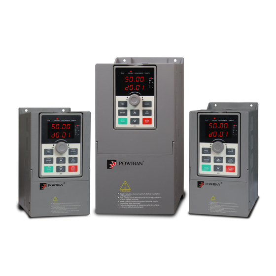
PI500A Series basic frequency inverter user manual
1. Foreword
Thank you for choosing POWTRAN PI500A serices basic frequency inverter .
The diagram of operating manual ,Maybe slightly different from the product for convenience of
explanation, Due to product upgrades, they may be slightly different. Please refer to the actual product.
The end-users should hold this manual,and keep it well for furture maintenance & care .
For any problem within the warranty period,please fill out the warranty card and fix it to our authorized
dealer
2. Instructions on nameplate
Model designation
POWTRAN Inverter
Serices Code
PI500A serices
Rated output capacity
2R2 : 2.2kW
004 : 4kW
3. Dimension
PI 500A 2R2
G 3
d
Note:0.75 to 4kW G3 supports rail mounting
0.75 to 4kW G3 dimensions
d
5.5 to 11kW G3 dimensions
A
W
15~22kW G3 dimensions
Input Voltage Level
1:Single-phase 220V 2:Three-phase 220V
3:Three-phase 380V 4:Three-phase 480V
Function code
F: Light load ,
G:Standard load
d
1 / 16
D1
D1
D1
D
Advertisement


Need help?
Do you have a question about the PI500A Series and is the answer not in the manual?
Questions and answers