Table of Contents
Advertisement
Foreword
Thank you for choosing POWTRAN PI9000-S Series Frequency Inverter. This product
made by POWTRAN is based on years of experience in professional production and
sale, and designed for solar pump inverter
This manual provides user the relevant precautions on installation, operational
parameter setting, abnormal diagnosis, routine maintenance and safe use. In order to
ensure correct installation and operation of the frequency converter, please carefully
read this manual before installing it.
For any problem when using this product, please contact your local dealer authorized by
Powtran or directly contact us, our professionals are happy to serve you.
The end-users should hold this manual, and keep it well for future maintenance & care,
and other application occasions. For any problem within the warranty period, please fill
out the warranty card and fax it to the our authorized dealer.
The contents of this manual are subject to change without prior notice. To obtain the
latest information, please visit our website.
For more product information, please visit: http://
www.powtran.com
POWTRAN
April, 2014
Advertisement
Table of Contents

Related Manuals for Powtran PI9000-S Series


Summary of Contents for Powtran PI9000-S Series
- Page 1 Foreword Thank you for choosing POWTRAN PI9000-S Series Frequency Inverter. This product made by POWTRAN is based on years of experience in professional production and sale, and designed for solar pump inverter This manual provides user the relevant precautions on installation, operational parameter setting, abnormal diagnosis, routine maintenance and safe use.
-
Page 2: Table Of Contents
Table of contents Foreword ....................... 1 Table of contents ....................2 Chapter 1.Inspection and safety precautions ............1 1-1. Inspection after unpacking ................1 1-1-1.Instructions on nameplate ................1 1-1-2.Safety precautions ..................1 1-2. Safety precautions ................... 2 1-3. Precautions...................... 4 1-4. - Page 3 5-1-1. d0Group - Monitoring function group ............24 5-1-2. F0 Group -Basic function group ..............26 5-1-3. F1 Input terminals group ................28 5-1-4. F2 Group - Output terminals group ............. 33 5-1-5. F3 Group - Start and stop control group ............37 5-1-6.
- Page 4 8-1. Operating environment .................. 71 8-2. Installation direction and space ..............71 8-3. Wiring diagram ..................... 71 Chapter 9 Maintenance and Repair................ 81 9-1. Inspection and Maintenance ................81 9-2. Parts for regular replacement ................. 82 9-3. Storage......................82 9-4. Capacitor ...................... 82 9-4-1.
-
Page 5: Foreword
Chapter 1.Inspection and safety precautions POWTRAN frequency inverters have been tested and inspected before leaving factory. After purchasing, please check if its package is damaged due to careless transportation, and if the specifications and model of the product are consistent with your order requirements. -
Page 6: Table Of Contents
Chapter1.Inspection and Safety Precautions 1-2.Safety precautions Safety precautions in this manual are divided into the following two categories: Danger: the dangers caused by failure to perform required operation, may result in serious injury or even death; Caution:the dangers caused by failure to perform required operation, may result in moderate injury or minor injury, and equipment damage;... - Page 7 Chapter1.Inspection and Safety Precautions The diameter of used wire shall refer to the recommendations of this manual. Otherwise it may cause an accident! ● Never directly connect braking resistor to the DC bus P(+) and P(-) terminals. Otherwise it may cause a fire! ●...
- Page 8 Chapter1.Inspection and Safety Precautions operation resistor to feel the temperature. Otherwise it may cause burns! ● Non-professional personnel is not allowed to detect signal when operating. Doing so may cause personal injury or damage to this unit! ● When the inverter is operating, you should avoid that objects fall into this unit.Otherwise cause damage to this unit! Note...
-
Page 9: Precautions
Chapter1.Inspection and Safety Precautions and noise certain amount of harmonics, so the temperature rise, noise and vibration of motor show a slight higher than frequency power frequency operation. Output side The inverter output is PWM wave, if the piezo-resistor for with piezo- lightning protection or the capacitor for improving power resistor or... -
Page 10: Scope Of Applications
Chapter1.Inspection and Safety Precautions when the rotational speed is reduced, therefore, when the motor works in overheating occasions, a strong exhaust fan should be retrofitted or replace non-inverter motor with the inverter motor. 3) The inverter has built-in the adaptive motor standard parameters, according to the actual situation, please identify motor parameters or accordingly modify the default values to try to meet the actual value, otherwise it will operation affect... - Page 11 Chapter1.Inspection and Safety Precautions ※ If the inverter is used in such equipments(e.g: equipments for lifting persons, aviation systems, safety equipment, etc.) and its malfunction may result in personal injury or even death. In this case, please consult the manufacturer for your application.
-
Page 12: Chapter 2 Standard Specifications
Chapter 2 Standard specifications 2-1.Technical specifications Rated Rated Inverter output output Adaptive Base Input voltage model power(kW current motor PI9130-S 0R4G1 1-phase PI9130-S 0R7G1 0.75 0.75 AC 220V PI9130-S 1R5G1 ± 10%; PI9130-S 2R2G1 recommend PI9130-S 004G1 DC 200V~380V PI9230-S 5R5G1 PI9130-S 0R4G2 PI9130-S 0R7G2 0.75... -
Page 13: Standard Specifications
Chapter2.Standard Specifications 2-2.Standard specifications Items Specifications Single-phase 220V± 10%,50/60Hz± 5% Voltage Three-phase 220V± 10%,50/60Hz± 5% frequency levels Three-phase 380V± 10%,50/60Hz± 5% Recommend pv G1/G2:DC 200~380V; input G3:DC 350~750V voltage range Control system High performance vector control inverter based on DSP Control method V/F control, vector control W/O PG Automatic... - Page 14 Chapter2.Standard Specifications Items Specifications Automatic Automatically maintain a constant output voltage when the voltage voltage of electricity grid changes regulation(AVR) the biggest Optical power tracking,Light weak auto The specific sleep,Light intensity automatically wake up,High water function of solar level automatic stop,Low water level automatic run,under pump inveter load protection.
- Page 15 Chapter2.Standard Specifications Items Specifications Limit frequency, jump frequency, frequency compensation, Run function auto-tuning, PID control DC current Built-in PID regulates braking current to ensure sufficient braking braking torque under no overcurrent condition. Running Three channels: operation panel, control terminals and serial communication port.
- Page 16 Chapter2.Standard Specifications Items Specifications Monitoring objects including: running frequency, set Runni frequency, bus voltage, output voltage, output current, output power, output torque, input terminal status, output LED/OL infor terminal status, analog AI1 value, analog AI2 value, motor matio Actual running speed ,PID set value percentage, PID display feedback value percentage.
-
Page 17: Dimensions
Chapter2.Standard Specifications 2-3.Dimensions 2-3-1.Appearance and installation holes size Top cover plate 上盖板 Operation panel 操作面板 活动盖板 Movable cover plate Sealing guard 防护密封片 mounting position 控制电缆入口 Control cable inlet 安装位(可选) (optional) Fixing holes 整机固定孔 风道进风口 Air duct inlet Nameplate 普传变频器铭牌 2-3-2.PI9100 series 9S2 to 9S4 WARNING Refer to the operation manual when adjust or inspect. - Page 18 Chapter2.Standard Specifications Power Dimensions Installation size Power supply Type (kW) level 1-phase 0.4 to 1.5 220V 3-phase 0.4 to 1.5 185 120 174 108 Ø5.3 220V 3-phase 0.75 to 2.2 380V Power supply Dimensions Installation size Power Type level (kW) 1-phase 220V 3-phase 220V 209 138 Ø5.3...
-
Page 19: Pi9200 Series
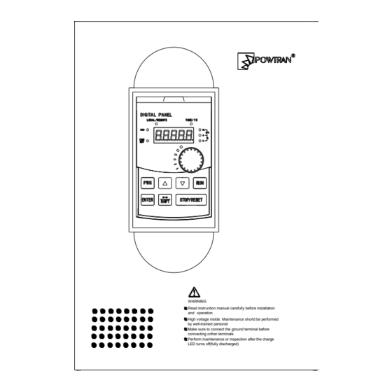
Chapter2.Standard Specifications 2-3-3.PI9200 series 9L1 to 9L3 WARNING Read instruction manual carefully before installation and operation High voltage inslde. Maintenance shorld be performed by well-trained personel Make sure to connect the ground terminal before connecting orther terminals Perform maintenance or inspection after the charge LED turns off(fully discharged) Power Dimensions... -
Page 20: Keyboard Size Diagram
Chapter2.Standard Specifications 2-3-4.Keyboard size diagram JP6E9100 size diagram: JP6D9200 keyboard case size diagram: Install keyboard case on the panel, opening square hole is required: (76±0.1)*(123±0.1)... -
Page 21: Chapter 3 Keyboard
Chapter 3 Keyboard 3-1.Keyboard description JPR6E9100 keyboard control panel Figure 3-1 Operation panel display 3-2.Keyboard Indicators Indicator flag Name Running indicator light * ON: the inverter is working * OFF: the inverter stops Command indicator light That is the indicator for keyboard operation, terminal LOCAL/RE operation and remote operation (communication control) MOTE... -
Page 22: Description Of Operation Panel Keys
Chapter3.Keyboard 3-3.Description of operation panel keys Sign Name Function Parameter * Enter into the modified status of main menu Setting/Esc * Esc from functional parameter modification * Esc submenu or functional menu to status menu *Choose displayed parameter circularly under running Shift Key or stop interface;... - Page 23 Chapter3.Keyboard Power-on Shutdown parameter display Change parameter group First-level menu display ENTER Change function parameter selection Second-level menu display Change function parameter ENTER ENTER value Third-level menu display Figure 3-2 Display status and operation processes Description: Back to the level 2 menu from level 3 menu by PRG key or ENTER key in the level 3 operation status.
-
Page 24: The Way To Read Parameters In Various Status
3-4-4.Motor parameter auto tunning Choose vector control, one must input the motor’s parameters in the nameplate accurately before running the inverter. PI9000-S series frequency inverter will match the motor’s standard parameters according to its nameplate. The vector control is highly depend on motor’s parameters. The parameters of the controlled motor must be inputted accurately for the good control performance. - Page 25 Chapter3.Keyboard speed For asynchronous motors If the motor can NOT completely disengage its load, please select 1 (asynchronous motor parameter static auto tunning) for b0.27, and then press the RUN key on the keyboard panel. If the motor can completely disengage its load, please select 2 (asynchronous motor parameter comprehensive auto tunning) for b0.27, and then press the RUN key on the keyboard panel, the inverter will automatically calculate the motor’s following parameters:...
-
Page 26: Chapter 4 Commissioning
Chapter 4 Commissioning Commissioning Select control manner ( Set F0.00 ) 0:Vector control W/O PG Correctly motor parameters F0.00=? ( Set b0.00 b0 . 05 ) 2 : V/F control Select appropriate ac/deceleration time Select command source Select suitable frequency source (... -
Page 27: Chapter 5 Function Parameter
PI9000-S series inverter , some parameters for the "factory reservations ", the serial number is not listed in the function parameter list , resulting in some of the parameters in the table number is not connected . -
Page 28: D0Group - Monitoring Function Group
Chapter5.Function parameter Referenc Code Parameter name Functional Description e page Auxiliary function To set Jog, frequency avoid and other group auxiliary function parameters Fault and protection To set fault and protection parameters Communication To set MODBUS communication parameter group function Control optimization To set parameters of optimizing the parameters... - Page 29 Chapter5.Function parameter Code Parameter name Functional description Unit Inverter output Effective value for Actual motor d0.04 0.01A current current Calculated value for motor d0.05 Motor output power 0.1kW output power d0.06 Reserved d0.07 DI input status DI input status d0.08 DO output status DO output status d0.09 AI1 voltage (V) AI1 input voltage value...
-
Page 30: F0 Group -Basic Function Group
Chapter5.Function parameter Code Parameter name Functional description Unit Master frequency Frequency set by F0.03 master d0.27 0.01Hz display frequency setting source Auxiliary frequency Frequency set by F0.04 auxiliary d0.28 0.01Hz display frequency setting source Observe the set command torque d0.29 Command torque (%) 0.1% under the torque control mode Display run, standby and other... - Page 31 Chapter5.Function parameter can not be too big. The inverter’s power can be two degree bigger or one degree smal ler than motor’s power. Otherwise, it will cause the control ability decrease or the dri ve system can not work normally. 50.0 0.00Hz to F0.19 (maximum frequency) Keyboard set...
-
Page 32: F1 Input Terminals Group
Chapter5.Function parameter Acceleration time ☆ F0.13 0.00s to 6500s Deceleration time ☆ F0.14 0.00s to 6500s Maximum output 50.0 ★ F0.19 50.00Hz to 320.00Hz frequency F0.21 setting Analog AI1 setting Analog AI2 setting Upper limit ★ F0.20 frequency source Panel potentiometer setting High-speed pulse setting Communication reference Setting upper limit frequency. - Page 33 Chapter5.Function parameter ★ DI4 terminal function F1.03 selection ★ DI5 terminal function F1.04 selection ★ DI6 terminal function F1.05 selection ★ DI7 terminal function F1.06 selection ★ DI8 terminal function F1.07 selection Set value Function Description The terminal for not use can be set to "no No function function"...
- Page 34 Chapter5.Function parameter The inverter slows down and stops, but all operating parameters are memorized. Such as Run pause PLC parameters, PID parameters. This terminal signal disappears, the inverter reverts to the previous state of running before parking. When the signal is sent to the inverter, inverter External fault normally trips fault Err.15, and performs troubleshooting open input...
- Page 35 Chapter5.Function parameter Of which, DIx and DIy are the multi-function input terminals of DI1 to DI10, the level is active. Command Stop Forward (FWD) Stop Reverse (REV) COM Digital common Terminals Two-wire mode 2: Three-wire control mode 1 In the mode, DIn is used as enabled terminal, while DIx, DIy terminal are used to control direction.
- Page 36 Chapter5.Function parameter To run, firstly close DIn terminal, the motor run signal is generated by the ascendant edge of DIx, the motor direction signal is generated by DIy status To stop, you must disconnect DIn terminal signals Of which, DIx, DIy and DIn are the multi-function input terminals of DI1 to DI10, DIx is for active pulse, DIy and DIn are for active level.
-
Page 37: F2 Group - Output Terminals Group
Chapter5.Function parameter sames as single digit ) digit DI5 terminal active thous status setting ( 0 to 1, ands sames as single digit ) digit ★ DI1 delay time 0.0s to 3600.0s 0.0s F1.37 ★ DI2 delay time 0.0s to 3600.0s 0.0s F1.38 ★... - Page 38 Chapter5.Function parameter No output No output action The inverter is in operation with output Inverter in service frequency (zero), and outputs ON signal. Fault output (fault When the inverter occurs failure and shutdown) stops, and outputs ON signal. Frequency level Please refer to the instructions of function detection FDT1 output code F7.23, F7.24...
- Page 39 Chapter5.Function parameter (shutdown without Outputs OFF signal when the inverter is in the output) state of stop Undervoltage status Outputs ON signal when the inverter is in output the undervoltage condition Communication Please refer to communication protocol. setting Reserved Reserved Outputs ON signal when the inverter Zero speed running 2 output frequency is 0.
- Page 40 Chapter5.Function parameter When the motor temperature reaches Motor F8.35 (motor overheat pre-alarm threshold), overtemperature pre- the output ON signal. (Motor temperature by warning d0.41 view) Outputs ON signal when the inverter's Current running time current running time exceeds the set time by arrival F7.45.
-
Page 41: F3 Group - Start And Stop Control Group
Chapter5.Function parameter pulse SPB terminal is selected as pulse output, the function code is used to select the maximum value of output pulse. SPB switching quantity ☆ F2.10 0.0s 0.0s to 3600.0s output delay time ☆ F2.11 0.0s Relay 1 output delay time 0.0s to 3600.0s ☆... -
Page 42: F4 V/Fcontrol Group
Chapter5.Function parameter DCpre-excitation ★ F3.05 0% to 100% current DCpre-excitation ★ F3.06 0.0s 0.0s to 100.0s time Start DC braking, generally is used to restart the motor after it stops. Pre-excitation is used to create magnetic field for asynchronous motor and then start the motor to improve the response speed. -
Page 43: F6 Keybaord And Display
Chapter5.Function parameter V/F half separeation 0.0%: Automatic torque boost ★ Torque boost F4.01 0.1%~30.0% ~ Torque boos cutoff F0.19( Maximum 0.00Hz ★ F4.02 15.00Hz frequency frequency ) Slip compensation ☆ F4.09 0.0% 0.0 %~200.0% gain This parameter is valid only for asynchronous motors. V/F slip compensation can compensate for the speed deviation of asynchronous motor when the increases, so as to keep stable speed when the load changes. -
Page 44: F7 Group - Auxiliary Function Group
Chapter5.Function parameter Setting frequency (Hz) Remain PLC range Bus voltage Load speed DI input situation PID setting DO output situation High speed pulse AI1 voltage input frequency (Hz) AI2 voltage Remain Remain Remain Remain Remain If the above parameters need to be displayed on operation, firstly set its position to 1, and then set at F6.03 after converting the binary number to the hexadecimal number. -
Page 45: F8 Group - Fault And Protection
Chapter5.Function parameter frequency) frequency ☆ F7.01 20.0s 0.0s to 6500.0s Jog acceleration time ☆ F7.02 20.0s 0.0s to 6500.0s Jog deceleration time Allow Reverse rotation ☆ F7.17 control Prohibit ☆ F7.22 Start protection This parameter is related to the security protection of the inverter. If this parameter is set to 1, if the time run command is effective when power on (for exa mple, the terminal run command is closed before power on), the drive does not respond t o the run command, you must firstly cancel the run command , after run command is agai... - Page 46 Chapter5.Function parameter according to the inverse time curve of motor overload protection. Inverse time curve of motor overload protection: 220% x (F8.03) x rated motor current, if this lasts for 1 second, the alarm of motor will be prompted overload fault; 150% x (F8.03) × rated motor current, if this lasts for 60 seconds, the alarm of motor overload will be prompted.
-
Page 47: F9 Group - Communication Parameter
Chapter5.Function parameter When the inverter selects automatic fault reset, it is used to set the number of times of automatic fault reset. If the set number of times is exceeded, the inverter remains a failed state. When set F8.10 (number of automatic fault reset) ≥ 1, inverter will run automatically when repower after instantaneous power-off. - Page 48 Chapter5.Function parameter 115200BPS 208300BPS 256000BPS 512000BPS Hundre Reserved ds digit Thousan CAN bus baudrate ds digit No parity (8-N-2) Even parity (8-E-1) ☆ F9.01 Data format Odd parity (8-O-1) No parity(8-N-1) 1 to 250, 0 for broadcast ☆ F9.02 This unit address address ☆...
-
Page 49: Fb Group - Control Optimization Parameters
Chapter5.Function parameter card type 1:Profibus communication card 2:Reserved 3:CAN bus communication card 5-1-11.FB Group - Control optimization parameters Chan Factory Code Parameter name Setting range range Limit Disable Fast current limiting ☆ FB.00 manner Enable Enable Quick Current Limiting function, which can minimize the overcurrent fault of inverter , and ensure the uninterrupted operation of inverter. - Page 50 Chapter5.Function parameter intervals after the search, the search result is as given value. Solar voltage Confirmed ☆ E0.01 0.0~1000.0V setting model type When set E0.00 to 1, this voltage is CVT mode bus voltage set value; When set E0.00 to 2, the voltage is the bus voltage given value when MPPT mode be started, and also the initial value when search voltage.
-
Page 51: E2 Pid Function Group
Chapter5.Function parameter detection interval time After the load drop fault, inverter will restart after this setting time (E0.10). 5-1-13.E2 PID Function Group Chan Factory Code Parameter name Setting range range Limit ☆ E2.00 PID setting source 0~6 keyboard ☆ E2.01 50.0% 0.0%~100.0% setting... - Page 52 Chapter5.Function parameter 0.0% : not judging feedback PID feedback loss ☆ E2.11 0.0% loss detection value 0.1%~100.0% PID feedback loss ☆ E2.12 0.0s 0.0s~20.0s detection time This function code is used to determine whether the PID feedback is loss. When the amount is less than the E2.11 value, and duration is longer than E2.12 value, inverter will alarm Err.31 fault, and process trouble-shooting according to the fault.
-
Page 53: E3 Virtual Terminal Group
Chapter5.Function parameter When automatic switch selected, when the deviation absolute value of “given value” and “feedback value” is smaller than E2.20, PID parameter select parameter group 1. when the deviation absolute value of “given value” and “feedback value” is bigger than E2.21, PID parameter select parameter group 2. - Page 54 Chapter5.Function parameter ★ E3.01 VDI2 function selection 0~50 ★ E3.02 VDI3 function selection 0~50 ★ E3.03 VDI4 function selection 0~50 ★ E3.04 VDI5 function selection 0~50 Virtual VDI1 ~ VDI5 functionally identical DI on control board, it can be used as a multi-function digital inputs, detailed settings please refer to introduction of F1.00 ~ F1.09.
- Page 55 Chapter5.Function parameter VDI is valid or invalid state depending on the VDO output valid or invalid, and VDIx only binding VDOx(x=1~5) When choosing VDI state selection function code to set, through the binary bits of E3.05 , respectively determine the state of virtual input terminals. Example of how to use VDI.
-
Page 56: B0 Motor Parameters Group
Chapter5.Function parameter output function See F2 group physical DO 1to40 selection output option With the physical internal Virtual VDO2 sub DIx ☆ E3.12 output function See F2 group physical DO selection 1to40 output option With the physical internal Virtual VDO3 sub DIx ☆... - Page 57 Chapter5.Function parameter Chan Factory Code Parameter name Setting range range Limit General asynchronous motor Motor type Asynchronous inverter ★ b0.00 selection motor Permanent magnet synchronous motor ★ b0.01 Rated power 0.1kW to 1000.0kW ★ b0.02 1V to 2000V Rated voltage ★...
-
Page 58: Y0 Function Code Management Group
Chapter5.Function parameter parameters but also encoder phase sequence and current loop PI parameters can be obtained by Asynchronous Motor Parameters Comprehensive Auto Tunning When modifying the motor's rated power (b0.01) or rated voltage (b0.02), the inverter will automatically calculate and modify the parameter values of b0.06 to b0.10 , and restore these 5 parameters to the motor parameters of commonly used standard Y Series. - Page 59 Chapter5.Function parameter motor parameters Clear history Restore default parameter values, including motor parameters Backup current user parameters Restore user backup parameters Clear keyboard storage area upload parameter keyboard storage area 1 upload parameter keyboard storage area 2 download the parameters from keyboard storage 1 area to the storage system download the parameters...
- Page 60 Chapter5.Function parameter otherwise can not view and modify the function parameters, please keep in mind the set user password. When y0.01 is set to 0, the set user password will be cleared, the password protection function is invalid. Units d group display selection digit Not display Display...
-
Page 61: Y1 Fault Query Group
Chapter5.Function parameter y1 Fault query group 5-1-17. Chan Factory Code Parameter name Setting range range Limit ● y1.00 0 to 51 Type of the first fault Type of the second ● y1.01 0 to 51 fault Type of the third(at ●... - Page 62 Chapter5.Function parameter abnormal Inverter hardware abnormal Motor short to ground Running time arrival Custom fault 1 Custom fault 2 Power-on time arrival Off load PID feedback loss when running Fast current limiting timeout Switch motor when running Reserved Motor overspeed Motor overtemperature Initial position error Frequency of the...
- Page 63 Chapter5.Function parameter for display. y1.08 Reserved Power-on time of Current power-on time of the last fault ● y1.09 the third fault Running time of Current running time of the last fault ● y1.10 the third fault y1.11 to Reserved y1.12 Frequency of the Frequency of the last fault ●...
- Page 64 Chapter5.Function parameter the first fault Input terminal status of the last fault, the order is: BIT9 BIT8 BIT7 BIT6 BIT5 BIT4 BIT3 BIT2 BIT1 BIT0 Input terminal ● y1.26 status of the first When the input terminal is ON, the fault corresponding binary bits is 1, OFF is 0, all DI status is converted to the decimal number...
-
Page 65: Chapter 6 Emc (Electromagnetic Compatibility)
Chapter 6 EMC (Electromagnetic Compatibility) 6-1.Definition Electromagnetic compatibility refers to the ability that the electric equipment runs in an electromagnetic interference environment and implements its function stably without interferences on the electromagnetic environment. 6-2.EMC standard In accordance with the requirements of the Chinese national standard GB/T12668.3, the inverter must comply with the requirements of electromagnetic interference and anti- electromagnetic interference. -
Page 66: Remedies For The Interferences From The Surrounding Electromagnetic
Chapter6.EMC(Electromagnetic Compatibility) 6-3-3.Remedies for the interferences from the surrounding electromagnetic equipments to the inverter Generally the electromagnetic interference on the inverter is generated by plenty of relays, contactors and electromagnetic brakes installed near the inverter. When the inverter has error action due to the interferences, the following measures is recommended: 1) Install surge suppressor on the devices generating interference;... -
Page 67: Precautions On Installing Emc Input Filter At The Input End Of Power Supply
Chapter6.EMC(Electromagnetic Compatibility) capacitance can be reduced by effectively reducing the distance between the inverter and the motor. The higher the carrier frequency, the larger the leakage current. The leakage current can be redUced by reducing the carrier frequency. However, the carrier frequency reduced may result in the increase of motor noise.Please note that additional installation of reactor is also an effective method to solve leakage current problem. -
Page 68: Chapter 7 Troubleshooting
Chapter 7 Troubleshooting PI9000-S can provide effective protection when the equipment performance is played fully. The following faults may appear in the process of use, please refer to the following table to analyze the possible causes and then trouble shoot. In case of damage to the equipment and the reasons that can not solved, please contact with your local dealers/agents, or directly contact with the manufacturers to seek solutions. - Page 69 Chapter7.Troubleshooting vector and without for the motor parameters identification of 6.select Speed Tracking parameters Start or restart after 6.the motor that is stopping the motor. rotating is started 7.cancel the sudden load unexpectedly. 8.choose the inverter 7.suddenly increase the with large power level load in the process of acceleration.
- Page 70 Chapter7.Troubleshooting high normal range 3.there is external force 3.cancel the external to drag the motor to run force or install braking when accelerating. resistor. 4.the acceleration time is 4.increase acceleration too short time 1.the input voltage is 1.set the voltage to the high normal range 2.there is external force...
- Page 71 Chapter7.Troubleshooting occurs mechanical conditions 1. power grid voltage is too low 1.check the power grid voltage 2.whether the setting motor protection 2.correctly set this parameters (F8.03) is Err.11 Motor Overload parameter. appropriate or not 3.reduce the load and 3.whether the load is too check the motor and its large or the motor stall mechanical conditions...
- Page 72 Chapter7.Troubleshooting 1.the communication cable is not normal 1.check the communication cable 2.the settings for communication 2.correctly set the expansion card F9.07 are communications incorrect expansion card type Communication Err.16 fault 3.the settings for 3.correctly set the communication communication parameters F9 group are parameters incorrect 4.check the wiring of...
- Page 73 Chapter7.Troubleshooting Input customer fault 1 Err.28 Custom fault 2 signal through the multi- Reset run function terminal DI. Clear history information Total power-on time Err.29 Total power-on by using initialization reaches the set value time arrival fault function parameters Confirm whether the load is removed or not or The inverter running the settings for...
- Page 74 Chapter7.Troubleshooting and the actual on whether the rated parameters is too large current is set to too small.
-
Page 75: Chapter 8 Installation And Commissioning Guidance
Chapter 8 Installation and Commissioning guidance. 8-1.Operating environment (1) Environmental temperature -10℃ to 50℃ Above 40℃,the capacity will decrease 3% by each 1℃.So it is not advisable to use inverter above 50℃ (2) Prevent electromagnetic interference, and away from interference sources. (3) Prevent the ingress of droplets, vapor, dust, dirt, lint and metal fine powder. - Page 76 Chapter8.Installation and Spare Circuit Function description of main circuit terminal Terminals Name Description R/L1 Connect to three-phase power Inverter input S/L2 supply, single-phase connects to R, terminals T;PV voltage connects to R, T T/L3 Ground terminals Connect to ground Braking resistor P+, RB Connect to braking resistor terminals...
- Page 77 Chapter8.Installation and Spare Circuit input Digital input 2 bipolar input 2.Input impedance: 2.4kΩ Digital input 3 3.Voltage range with level input: 9V to 30V Digital input 4 4 . Below 11KW: (DI1 to DI6)drive manner Digital input 5 is controlled by J5, when external power Digital input 6 supply is used to drive, please unplug J5 Digital input 7...
-
Page 78: Wiring Diagram
Chapter8.Installation and Spare Circuit Wiring diagram(< 7.5kW) - Page 79 Chapter8.Installation and Spare Circuit Wiring diagram(11kW to 15kW)
- Page 80 Chapter8.Installation and Spare Circuit 1. Wiring in accordance with the wiring diagram and closing the switch Q1 after checking the corrected wiring. 2. y0.00=1(Factory Reset); Set b0.00 ~ b0.05 motor parameters according to the motor nameplate. 3.Set F0.03 = 8 (PV settings); E0.00 = 2 (MPPT mode); 4.After setting the parameters, press the RUN key, observe the operating frequency and the water situation.
- Page 81 Chapter8.Installation and Spare Circuit High level detection point frequency Water inverter Tower Low level detection point Connect the test line according to the figure. Set parameters: F0.03 = 8 (PV settings)) F0.11 = 4 (keyboard + Terminal + communication); F1.00 = 1 (forward run); F1.01 = 8 (freewheel);...
- Page 82 Chapter8.Installation and Spare Circuit Set parameters: F0.03 = 8 (PV settings)); E0.00 = 2 (MPPT mode); E3.07 = 10 (run pause); After setting the parameters, press the RUN key. When AI1 voltage is below 7V, inverter runs; If the water tower above the high level detection point, the inverter belongs to standby status.
-
Page 83: Wiring Precautions
Chapter8.Installation and Spare Circuit Frequency inverter Water Tower U V W Well Start checkpoint Pump Low level detection points Parameter settings: F0.03 = 8 (PV settings); F0.11 = 4 (keyboard + Terminal + communication); F1.00 = 1 (forward run); F1.01 = 8 (freewheel); F1.10 = 2 (three-wire mode 1);... - Page 84 Chapter8.Installation and Spare Circuit ※The U, V, W output end of inverter can not install phase advancing capacitor or RC absorbing device. The inverter input power must be cut off when replacing the motor ※Do not let metal chips or wire ends into inside the inverter when wiring, otherwise which may cause malfunction to the inverter.
-
Page 85: Chapter 9 Maintenance And Repair
Chapter 9 Maintenance and Repair 9-1.Inspection and Maintenance During normal use of the inverter, in addition to routine inspections, the regular inspections are required (e.g. the overhaul or the specified interval, and the interval shall not exceed 6 months), please refer to the following table to implement the preventive measures. -
Page 86: Parts For Regular Replacement
Chapter9.Mainterance and Repair input voltage, the rectifier voltmeter for output voltage, the clamp-on ammeter for input current and output current, and the electric wattmeter for power. 9-2.Parts for regular replacement To ensure the reliable operation of inverter, in addition to regular care and maintenance, some internal mechanical wear parts(including cooling fan, filtering capacitor of main circuit for energy storage and exchange, and printed circuit board) shall be regularly replaced. -
Page 87: Measuring And Readings
Chapter9.Mainternance and Repair -- Last 100% rated power 2hours. Instruction of using adjustable power to charge the frequency inverter: The adjustable power is decided by the frequency inverter input power, for the single phase/3 phase 220v frequency inverter, we uase 220v AC/2A Regulator. Both single phase and three phase frequency inverter can be charged by single phase Power Surge(L+ connect R,N connects T) Because it is the same rectifier,so al l the DC bus capacitor will be charged at the same time. -
Page 88: Chapter 10 Warranty
Chapter 10 Warranty The product quality shall comply with the following provisions: 1. Warranty terms 1-1. The product from the user the date of purchase, the warranty period of 12 months (limited to domestic market). 1-2. Export products and non-standard products warranty period is 12 months or according to the agreement of warranty execution. -
Page 89: Appendix I Recommended Solar Array Configuration
Appendix I Recommended solar array configuration The solar cell module open circuit voltage level 20± 3V 30± 3V 36± 3V 42± 3V Seria Seria Seria Seria Seria pone pone pone pone pone erte Powe Powe Powe Powe Powe r± 5W inpu ±... -
Page 90: Appendix Ii Rs485 Communication Protocol
Appendix II RS485 Communication protocol II-1 Communication protocol II-1-1 Communication content This serial communication protocol defines the transmission information and use format in the series communication Including: master polling( or broadcast) format; master encoding method, and contents including: function code of action, transferring data and error checking. - Page 91 Appendix II 9K-RS485_S connect to 9KLCB control board 9K-RS485_S connect to 9KSCB control board 3-4-5.Link RS485 communication cables to inverter control terminals (SG+), (SG-). 3-4-6.When using RS485 transform, connect Inverter “SG+” to RS485 “T+”, Inverter “SG-” to RS485 “T-”. 3-4-7.After Confirming connection again, turn on inverter power. 3-4-8.If connection is right, set communication parameters as following: 3-4-9.F9.00 baud rate 0:300, 1:600, 2:1200, 3:2400, 4:4800, 5:9600;6:...
- Page 92 Appendix II 19200;7:38400;8:57600;9:115200 3-4-10.F9.02current inverter communication address 1~247 (If there are more than 1 inverters, don’t use the same number); 3-4-11.When using RS485 running control methods, set F0.11=2,choice RS485 running control method Match register 120ohm 1/4W RS485 converter SG- SG+ SG- SG+ ……...
- Page 93 Appendix II will be the address field of a new message. Similarly, if a new message begins earlier than the interval of 3.5 characters following a previous message, the receiving device will consider it as a continuation of the previous message. This will result in an error, because the value in the final CRC field is not right.
-
Page 94: Ii-2 Check Mode
Appendix II CRC CHK high-order When F9.05 is set to 1: Byte number Data F002H high-order Data F002H low-order Data F003H high-order Data F003H low-order CRC CHK low-order CRC CHK values are to be calculated CRC CHK high-order Command Code: 06H, write a word. For example:Write 5000(1388H)into the address F00AH of the inverter with slave address 02H. - Page 95 Appendix II an error in the transmission. The CRC firstly stores 0xFFFF and then calls for a process to deal with the successive eight-bit bytes in message and the value of the current register. Only the 8-bit data in each character is valid to the CRC, the start bit and stop bit, and parity bit are invalid.
-
Page 96: Ii-3 Definition Of Communication Parameter Address
Appendix II II-3 Definition of communication parameter address The section is about communication contents, it’s used to control the operation, status and related parameter settings of the inverter. Read and write function-code parameters (Some functional code is not changed, only for the manufacturer use or monitoring): the rules of labeling function code parameters address: The group number and label number of function code is used to indicate the parameter address:... - Page 97 Appendix II 100B AI2 voltage 100C Reserve 100D Reserve 100E Reserve 100F Load speed 1010 PID setting 1011 PID feedback 1012 PLC step 1013 High-speed pulse input frequency, unit: 0.01kHz 1014 Reserve 1015 Remaining run time 1016 AI1 voltage before correction 1017 AI2 voltage before correction 1018...
- Page 98 Appendix II Command word address Command function 0001: Forward run 0002: Reverse run 0003: Forward Jog 2000 0004: Reverse Jog 0005: Free stop 0006: Deceleration and stop 0007: Fault reset Inverter read status: (read-only) Status word address Status word function 0001: Forward run 3000 0002: Reverse run...
- Page 99 Appendix II Command address Command content 2004 0 to 7FFF indicates 0% to 100% Inverter fault description: Inverter fault address: Inverter fault information: 0000: No fault 0001: Inverter unit protection 0002: Acceleration overcurrent 0003: Deceleration overcurrent 0004: Constant speed overcurrent 0005: Acceleration overvoltage 0006: Deceleration overvoltage 0007: Constant speed overvoltage...
- Page 100 Appendix II 0006: Invalid parameter changes 0007: System locked 0008: EEPROM in operation F9 Group - Communication parameter description 6005 Baud rate Default Units digit: MODUBUS baud rate 0: 300BPS 1: 600BPS 2: 1200BPS 3: 2400BPS F9.00 4: 4800BPS Setting range 5: 9600BPS 6: 19200BPS 7: 38400BPS...
- Page 101 Appendix II Whenthe function code is set to valid, if the interval time between one communication and the next communication exceeds the communication time-out time, the system will report communication failure error (Fault ID Err.16). Generally, it is set to invalid. If the parameter can be set to monitor the communication status in continuous communication system.
-
Page 102: Warranty Card
Warranty Card Sincerely thank you purchase Powtran products ! This product has passed the strict quality inspection by Powtran. According to the instructions of this warranty card, Powtran will be responsible for free maintenance for all hardware failures caused by product quality problem under normal use during the warranty period. - Page 103 Customer Feedback Form of Powtran Inverter Failure Dear Customer: please fill out the form below in details so that we may better serve you: Load and control situation Electric Frequency range Rated motor power current under normal working poles □Fan□Textile machine□Extruder...
- Page 104 The following fields shall be filled out by maintenance agency Maintenance records: Full name of maintenance agency 1st time Address Zip Code Maintenance Signature voucher of the number serviceman Full name of maintenance agency Address Zip Code time Maintenance Signature voucher of the number...
- Page 105 Product Information Feedback Dear user: Thank you for your interest in and purchasing Powtran products! In order to better serve you, we want to be able to timely get your personal information and the related information of the purchased Powtran products so as to understand your current and future further demand to Powtran products, we would appreciate your valuable feedback.
Need help?
Do you have a question about the PI9000-S Series and is the answer not in the manual?
Questions and answers