Table of Contents
Advertisement
Thank you for choosing POWTRAN PI130 Series Frequency Inverter. This
product made by POWTRAN is based on years of experience in professional production
and sale, and designed for variety of industrial machinery, fan and water pump drive
unit and IF heavy-duty grinding unit.
This manual provides user the relevant precautions on installation,operational
parameter setting, abnormal diagnosis, routine maintenance and safe use. In order to
ensure correct installation and operation of the frequency converter, please carefully
read this manual before installing it.
For any problem when using this product, please contact your local dealer
authorized by this company or directly contact this company, our professionals are
happy to serve you.
The end-users should hold this manual,and keep it well for future maintenance &
care,and other application occasions. For any problem within the warranty period,please
fill out the warranty card and fax it to the our authorized dealer.
The contents of this manual are subject to change without prior notice. To obtain
the latest information, please visit our website.
For more product information, please visit: http://www.powtran.com.
Foreword
I
POWTRAN
July,2013
Advertisement
Table of Contents

Related Manuals for Powtran pi130 series


Summary of Contents for Powtran pi130 series
- Page 1 Foreword Thank you for choosing POWTRAN PI130 Series Frequency Inverter. This product made by POWTRAN is based on years of experience in professional production and sale, and designed for variety of industrial machinery, fan and water pump drive unit and IF heavy-duty grinding unit.
-
Page 2: Table Of Contents
Chapter 2 Standard Specifications ................8 2-1. Technical Specifications ............... 8 2-2. Standard specifications ................. 9 2-3. Dimensions ..................12 2-3-1. PI130 Series ................13 2-3-2. Keyboard size diagram............... 15 Chapter 3 Keyboard....................16 3-1. Keyboarddescription ................16 3-2. Keyboard Indicators ................16 3-3. - Page 3 5-1-5. F3 Group - Start and stop control ..........30 5-1-6. F4 Group - V/F control............... 31 5-1-7. F5 Group - Vector control group ..........32 5-1-8. F6 Group - Keyboard and display ..........32 5-1-9. F7 Group - Auxiliary function ............ 34 5-1-10.
- Page 4 5-2-14. E0 Group - Wobbulate control group ........77 5-2-15. E1 Group - Multi-speed control group ........78 5-2-16. E2 Group - PID control group ..........80 5-2-17. E3 Group - Virtual DI, virtual DO group ........83 5-2-18. b0 Group - Motor parameter group ........... 87 5-2-19.
- Page 5 8-6. Wiring Precautions: ................102 8-7. Spare Circuit ..................102 Chapter 9 Maintenance and Repair ..............104 9-1. Inspection and Maintenance .............. 104 9-2. Parts for regular replacement ............105 9-3. Storage..................... 105 9-4. Measuring and readings ..............106 Chapter 10 Warranty ................... 107 Appendix I RS485 Communication Protocol...........
-
Page 7: Chapter 1 Inspection And Safety Precautions
Chapter 1 Inspection and Safety Precautions Chapter 1 Inspection and Safety Precautions POWTRAN frequency inverters have been tested and inspected before leaving factory. After purchasing, please check if its package is damaged due to careless transportation, and if the specifications and model of the product are consistent with your order requirements. -
Page 8: Safety Precautions
Chapter 1 Inspection and Safety Precautions 1-2.Safety Precautions Safety precautions in this manual are divided into the following two categories: Danger: the dangers caused by failure to perform required operation, may result in serious body injury or even death; Caution:the dangers caused by failure to perform required operation,may result in moderate injury or minor injury, and equipment damage;... - Page 9 Chapter 1 Inspection and Safety Precautions Process Type Explanation do not incorrectly connect wires! Otherwise which may cause damage to the driver! ★ Ensure that the distribution line meets the regional safety standards of EMC requirements. The diameter of used wire shall refer to the recommendations of this manual.
- Page 10 Chapter 1 Inspection and Safety Precautions Process Type Explanation injury or damage to this unit! ★ When the inverter is operating, you should avoid that objects fall into this unit.Otherwise cause damage to this unit! ★ Do not start/stop the driver by switching on/off Note contactor.
- Page 11 Chapter 1 Inspection and Safety Precautions Type Explanation The inverter output voltage is PWM wave that contains a Motor heat and certain amount of harmonics, so the temperature rise,noise noise and vibration of motor show a slight higher than frequency power frequency operation.
- Page 12 Chapter 1 Inspection and Safety Precautions Type Explanation 2) The cooling fan and the rotor shaft for non-inverter motor are coaxially connected, the fan cooling effect is reduced when the rotational speed is reduced, therefore, when the motor works in overheating occasions,a strong exhaust fan should be retrofitted or replace non-inverter motor with the inverter motor;...
-
Page 13: Scope Of Applications
Chapter 1 Inspection and Safety Precautions 1-4.Scope of applications ※ This inverter only applies to typical industrial three-phase AC asynchronous motor. ※ This inverter can only be used in those occasions recognized by this company, an unapproved use may result in fire, electric shock, explosion and other accidents. ※... -
Page 14: Chapter 2 Standard Specifications
Chapter 2 Standard Specifications Chapter 2 Standard Specifications 2-1.Technical Specifications Rated Rated Adaptive Inverter Input output input Rated output motor model voltage Power Current current (A) Power (KW) (KW) PI130- 0R4G1 Single PI130- phase 0.75 0.75 0R7G1 220V ± 10% PI130- 14.0 1R5G1... -
Page 15: Standard Specifications
Chapter 2 Standard Specifications 2-2.Standard specifications Items Specifications Voltage and Single phase 220V, 50/60Hz frequency levels Three-phase 220V, 50/60Hz Allowable Voltage: ± 10% fluctuation Frequency: ± 5% High performance vector control inverter based on Control system Output frequency 0.00 to 400.0Hz V/F control Control method Open-loop flux vector control... - Page 16 Chapter 2 Standard Specifications Items Specifications operation terminal Easy to realize closed-loop control system for the Built-in PID process control. Automatic voltage Automatically maintain a constant output voltage when regulation (AVR) the voltage of electricity grid changes Running Keyboard/terminal/communication method Frequency Total 8 frequency stetting modes: digital,analog setting...
- Page 17 Chapter 2 Standard Specifications Items Specifications Total 8 frequency sources: digital,analog voltage,analog current, multi-speed and serial port. Frequency source They can be switched through a variety of ways. 5 digital input terminals, compatible with the active Input terminals PNP or NPN input. 2 Analog input terminals One digital output terminals (bipolar output) ;...
-
Page 18: Dimensions
Chapter 2 Standard Specifications Items Specifications -10 ℃ to 40 ℃ (temperature at 40 ℃ to 50 ℃, Environment temperature please derating for use) -20 ℃ to 65 ℃ Storage temperature Environment Less than 90% RH, non-condensing water droplets humidity Height and vibration Below 1000m, below 5.9m/s²... -
Page 19: Pi130 Series
Chapter 2 Standard Specifications 2-3-1.PI130 Series Power supply level Type Power (KW) Single-phase 220V 0.4 to 0.75 3-phase 220V 0.4 to 0.75... - Page 20 Chapter 2 Standard Specifications 2. 1M3 Power supply level Type Power (KW) Single-phase 220V 3-phase 220V...
-
Page 21: Keyboard Size Diagram
Chapter 2 Standard Specifications 2-3-2.Keyboard size diagram JP130 size diagram:... -
Page 22: Chapter 3 Keyboard
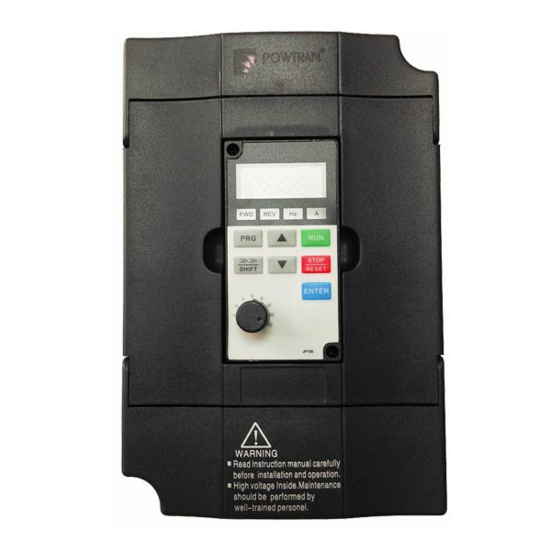
Chapter 3 Keyboard Chapter 3 Keyboard 3-1.Keyboarddescription Keyboard Schematic Diagram 3-2.Keyboard Indicators Indicator flag Name Meaning Forward running ON means that the inverter is forward lamp operating. ON means that the inverter is reverse Reverse running lamp operating. Frequency Indicator Frequency unit of the inverter Current Indicator Current unit of the inverter... -
Page 23: Description Of Operation Panel Keys
Chapter 3 Keyboard 3-3.Description of operation panel keys Sign Name Function * Enter top menu parameter change status Parameter * Exit from function option change Setting/Exit Key * Return to status display menu from sub-menu or function option menu * Select circularly parameters under run or stop Shift Key interface;... - Page 24 Chapter 3 Keyboard level menu) → function code (second level menu) → function code settings (third level menu) . The operation flow is shown in the figure. Description: return to the second-level menu from the third-level menu by pressing PRG key or ENTER key.
-
Page 25: Password Settings
Chapter 3 Keyboard In the third-level menu status, if the parameter has not blinking bit, it means that the function code can not be modified, the possible causes include: 1) The function code can not be used to modify the parameters. Such as actual detection parameters, run record parameters. - Page 26 Chapter 3 Keyboard b0.02: motor rated voltage b0.03: motor rated current b0.04: motor rated frequency b0.05: motor rated speed If the motor can completely disengage its load, please select 1 (asynchronous motor parameter comprehensive auto tunning) for b0.11, and then press the RUN key on the keyboard panel: If the motor can NOT completely disengage its load, please select 2 (asynchronous motor parameter static auto tunning) for b0.11, and then press the RUN key on the...
-
Page 27: Chapter 4 Commissioning
Chapter 4 Commissioning Chapter 4 Commissioning Commission- Select control manner (setting F0.00) Open-loop flux Configure correctly motor vector control F0.00=? parameters b0.01 to b0.05 group Select appropriate control ac/deceleration time(setting F0.05, F0.06) Motor parameter auto Select run command tunning fault(setting channel(setting F0.04) b0.11) Select appropriate frequency... -
Page 28: Chapter 5 Function Parameter
Chapter 5 Function parameter Chapter 5 Function parameter 5-1.Menu grouping PI130 inverter function parameters are grouped by function, there is d0 group, F0 group to Fb group, E0 group to E3 group, b0 group, y0 group to y1 group, L0 group, a total of 21 groups. -
Page 29: D0 Group - Monitoring Function
Chapter 5 Function parameter Reference Code Parameter Group Name Functional Description page Keyboard and display To set key and display function group parameters To set Jog, jump frequency and other F7 Auxiliary function group auxiliary function parameters Fault and protection To set fault and protection parameters group Communication... - Page 30 Chapter 5 Function parameter Smallest Reference No. Code Parameter name Functional Description Change unit page Inverter output Inverter actual output ● d0.03 voltage voltage Inverter output Inverter actual output ● d0.04 0.1A current current Inverter output Inverter actual output ● d0.05 0.1kW power...
-
Page 31: F0 Group - Basic Function
Chapter 5 Function parameter Smallest Reference No. Code Parameter name Functional Description Change unit page Cumulative ● d0.19 0 to 65535h running time of this unit Observe the set command torque under d0.20 Torque setting ● 0.1% speed mode or torque value control mode 5-1-2.F0 Group - Basic function... - Page 32 Chapter 5 Function parameter Factory Reference No. Code Parameter name Setting range Change default page 0: Keyboard command channel Command 1: Terminal command ★ F0.04 source channel channel 2: Communication command channel Depends Acceleration ☆ F0.05 0.1 to 3600.0s time 1 models Depends Deceleration...
-
Page 33: F1 Group - Input Terminals
Chapter 5 Function parameter Factory Reference No. Code Parameter name Setting range Change default page 0: Invalid AVR function 1: full valid ☆ F0.13 selection 2: only invalid during deceleration 5-1-3.F1 Group - Input terminals Factory Reference No. Code Parameter name Setting range Change default... - Page 34 Chapter 5 Function parameter Factory Reference No. Code Parameter name Setting range Change default page (returns to the center frequency) 22: Torque control prohibited 23: Frequency change settings temporarily clear 24: Stop DC braking 25: Reserved Two-wire type control 1 Two-wire type Terminal control...
-
Page 35: F2 Group - Output Terminals
Chapter 5 Function parameter Factory Reference No. Code Parameter name Setting range Change default page input Times of switching ☆ F1.18 1 to 10 quantity filtering DI terminal mode ☆ F1.19 0x000 to 0x1FF selection 5-1-4.F2 Group - Output terminals Factory Reference Code... -
Page 36: F3 Group - Start And Stop Control
Chapter 5 Function parameter Factory Reference Code Parameter name Setting range Change default page AO1 output lower ☆ F2.05 0.0% to F2.07 0.0% limit Lower limit ☆ F2.06 corresponds to AO1 0.00V to 10.00V 0.00V output AO1 output upper ☆ F2.07 F2.05 to 100.0% 100.0%... -
Page 37: F4 Group - V/F Control
Chapter 5 Function parameter Factory Reference No. Code Parameter name Setting range Change default page Waiting time of ☆ F3.07 0.0 to 50.0s 0.0 s stop braking Stop DC braking ☆ F3.08 0.0 to 150.0% 0.0% current Stop DC braking ☆... -
Page 38: F5 Group - Vector Control Group
Chapter 5 Function parameter Factory Reference No. Code Parameter name Setting range Change default page V/F slip ☆ F4.09 compensation 0.0 to 200.0% 0.0% limit 5-1-7.F5 Group - Vector control group Factory Reference No. Code Parameter name Setting range Change default page Speed loop... - Page 39 Chapter 5 Function parameter Factory Reference No. Code Parameters Setting range Change default page 0 to 0xFFFF BIT0: Running frequency BIT1: Set frequency BIT2: Bus voltage BIT3: Output voltage BIT4: Output current BIT5: Running speed BIT6: Output power BIT7: Output torque BIT8: PID setting Running status value...
-
Page 40: F7 Group - Auxiliary Function
Chapter 5 Function parameter Factory Reference No. Code Parameters Setting range Change default page value. BIT10 to BIT15: Reserved Speed display ☆ F6.03 0.1 to 999.9% 100.0% coefficient F6.04 to Reserved F6.07 5-1-9.F7 Group - Auxiliary function Factory Reference No. Code Parameter name Setting range Change... -
Page 41: F8 Group - Fault And Protection
Chapter 5 Function parameter Factory Reference No. Code Parameter name Setting range Change default page running selection command Invalid 1: Power terminals running command Valid 0.00 to F0.08 FDT level detection (maximum ☆ F7.10 50.00Hz 109. value output frequency) FDT hysteresis 0.0 to 100.0% ☆... -
Page 42: F9 Group - Communication Parameter
Chapter 5 Function parameter Factory Reference No. Code Parameter name Setting range Change default page 20.0% to 120.0% Motor overload ☆ F8.04 (rated motor 100.0% 117. protection current current) Overvoltage stall 0: Disable ☆ F8.05 118. protection 1: Enable Overvoltage stall 110 to 150% (220V ☆... - Page 43 Chapter 5 Function parameter Factory Reference No. Code Parameter name Setting range Change default page 5: odd parity (O, 8, 2) for 6: no parity (N, 7, 1) for ASCII 7: even parity (E, 7, 1) for ASCII 8: odd parity (O, 7, 1) for ASCII 9: no parity (N, 7, 2) for ASCII...
-
Page 44: Fa Group - Torque Control
Chapter 5 Function parameter Factory Reference No. Code Parameter name Setting range Change default page communication control mode only) 3: No alarm and stop at the selected mode (under all control modes) 0: Write operations Transmission responded ☆ F9.07 131. response handling 1: Write operations not responded... -
Page 45: E0 Group - Wobbulate Control
Chapter 5 Function parameter Factory Reference No. Code Parameter name Setting range Change default page High-frequency ☆ Fb.04 threshold point of 0 to 500 138. oscillation suppression Amplitude limit value ☆ Fb.05 of oscillation 0 to 10000 5000 139. suppression Demarcation 0.00Hz to F0.08 frequency of high and... -
Page 46: E2 Group - Pid Control
Chapter 5 Function parameter No. Code Parameter name Setting range Factory default Change Reference page ☆ E1.02 Multi-speed 2 -100.0 to 100.0% 0.0% 151. ☆ E1.03 Multi-speed 3 -100.0 to 100.0% 0.0% 152. ☆ E1.04 Multi-speed 4 -100.0 to 100.0% 0.0% 153. -
Page 47: E3 Group - Virtual Di, Virtual Do
Chapter 5 Function parameter Factory Reference No. Code Parameter name Setting range Change default page source selection AI1 feedback 1: Analog channel AI2 feedback 2: Panel potentiometer feedback 3: AI1-AI2 feedback 4: Remote communications feedback 5: AI1+AI2 feedback 6: MAX (︱AI1︱, ︱AI2︱) 7: MIN (︱AI1︱, ︱AI2︱) - Page 48 Chapter 5 Function parameter Factory Reference No. Code Parameter name Setting range Change default page 176. ★ E3.00 VDI1 function 0 to 25 selection 177. ★ E3.01 VDI2 function 0 to 25 selection 178. ★ E3.02 VDI3 function 0 to 25 selection 179.
-
Page 49: B0 Group - Motor Parameters
Chapter 5 Function parameter Factory Reference No. Code Parameter name Setting range Change default page Units digit: VDO1 0: positive logic 1: negative logic 192. ☆ E3.16 VDO valid state Tens digit: VDO2 00000 (same as units digit) Hundreds digit: VDO3 (same as units digit) 193. -
Page 50: Y0 Group - Function Code Management
Chapter 5 Function parameter Factory Reference No. Code Parameter name Setting range Change default page Motor stator and Depends ☆ b0.08 0.1 to 6553.5mH 206. rotor inductance on models Motor stator and Depends ☆ b0.09 rotor mutual 0.1 to 6553.5mH 207. - Page 51 Chapter 5 Function parameter Setting Factory Reference No. Code Parameter name Change range default page ● Bus voltage of current y1.05 217. fault ● Input terminal status of y1.06 218. current fault Output terminal status of ● y1.07 219. current fault...
-
Page 52: Function Parameter Description
Chapter 5 Function parameter 5-2.Function parameter description 5-2-1.dO Group - Monitoring function group d0 parameters group is used to monitor the inverter running status information,user can view those information through the panel to facilitate on-site commissioning, also read parameters group value via communication for host computer monitoring. Parameter function code Parameter name Smallest unit... -
Page 53: F0 Group - Basic Function Group
Chapter 5 Function parameter Parameter function code Parameter name Smallest unit Displays current output terminal state value. When it is converted into binary data, one bit corresponds to one output terminal input signal, 1 indicates that the input terminal is high level signal, 0 indicates that the output terminal is low-level signal. - Page 54 Chapter 5 Function parameter Factory Code Parameter name Setting range Change default Open-loop flux vector control Reserved ★ F0.00 Control mode V/F control Torque control Select the operating mode of inverter: 0: open-loop flux vector control: refers to that the open-loop flux vector control is suitable for high-performance general-purpose applications where the encoder PG is not installed, an inverter can only drive one motor.
- Page 55 Chapter 5 Function parameter Factory Code Parameter name Setting range Change default 2: Analog AI2 setting 3: Panel potentiometer setting Refers to that the frequency is determined by the analog input terminals, PI130 inverter is equipped with standard two-way analog input terminals (AI1, AI2), AI1/AI2 voltage and current optional (0V to 10V/0mA to 20mA), it can be switched by the jumpers JP2 and JP3 on control panel.
- Page 56 Chapter 5 Function parameter Factory Code Parameter name Setting range Change default 2: UP/DOWN setting is invalid, keyboard ▲ and ▼ keys and input terminals UP/DOWN function is invalid. 3: Set keyboard ▲ and ▼ keys and terminal UP/DOWN function setting as valid when running, set keyboard ▲...
- Page 57 Acceleration and deceleration time schematic that the set frequency is less than the maximum frequency. PI130 series inverter has two groups of deceleration time. First group: F0.05, F0.06; second group: F7.03, F7.04 Acceleration and deceleration time can be selected by using the multi-function input terminals (F1 group) .
- Page 58 Chapter 5 Function parameter Factory Code Parameter name Setting range Change default Analog AI2 setting Multi-speed setting Remote communications setting To define the setting mode for upper limit. The upper limit frequency can be set from either digital setting (F0.10), also from analog input channels, multi-speed setting or communication settings.
-
Page 59: F1 Gruop - Input Terminals Group
Chapter 5 Function parameter 5-2-3.F1 Gruop - Input terminals group Factory Code Parameter name Setting range Change default 0: No function 1: Forward run (FWD) 2: Reverse run (REV) F1.00 DI1 terminal function 3: Three-wire operation ★ selection control 4: Forward Jog 5: Reverse Jog 6: Frequency setting increment (UP) - Page 60 Chapter 5 Function parameter Factory Code Parameter name Setting range Change default 4: Forward Jog 5: Reverse Jog For the specific Jog running frequency and Jog Ac/deceleration time, please see the instructions of F7.00 to F7.02 function code. 6: Frequency setting increment (UP) 7: Frequency setting decrement (DOWN) Modify frequency increment/decrement command when the frequency is referenced by external terminal.
- Page 61 Chapter 5 Function parameter Factory Code Parameter name Setting range Change default revoked, the inverter will continue wobbulate at the current frequency. 21: Wobbulate reset: the set frequency of inverter gets back to the center frequency. 22: Torque control prohibited: the Inverter switches from torque control mode to speed control mode.
- Page 62 Chapter 5 Function parameter Factory Code Parameter name Setting range Change default Running Stop button direction Forward Forward button Reverse Reverse button Three-wire control mode 1 Three-wire control mode 2 Change rate of terminal 0.50Hz/ ☆ F1.07 UP/DOWN frequency 0.01 to 50.00Hz/s increment When the terminal UP/DOWN is used to adjust the set frequency, the rate of frequency change, i.e.
-
Page 63: F2 Group - Output Terminals Group
Chapter 5 Function parameter Factory Code Parameter name Setting range Change default appropriately, the anti-interference of analog will be enhanced, but the analog input sensitivity will be weakened. ☆ 0.00V F1.13 AI2 lower limit 0.00V to F1.15 ☆ 0.0% F1.14 AI2 lower limit setting -100.0% to 100.0% ☆... - Page 64 Chapter 5 Function parameter Factory Code Parameter name Setting range Change default No output The function of Output terminal is disabled. Inverter Run Forward: when the inverter Motor is running runs forward, if the frequency output exists, forward ON signal will output. Inverter Run Reverse: when the inverter Motor is running runs reverse, if the frequency output exists,...
- Page 65 Chapter 5 Function parameter Factory Code Parameter name Setting range Change default Running 0 to maximum output frequency frequency Set frequency 0 to maximum output frequency Output current 0 to 2 times of rated inverter current Output torque 0 to 2 times of rated motor current Output power 0 to 2 times of rated power Output voltage...
-
Page 66: F3 Group - Start And Stop Control Group
Chapter 5 Function parameter Factory Code Parameter name Setting range Change default status selection This function code is used to set the polarity of the input terminals. When the bit is set to 0, the polarity of output terminal is positive; when the bit is set to 1, the polarity of output terminal is negative. -
Page 67: F4 Group - V/F Control Group
Chapter 5 Function parameter Factory Code Parameter name Setting range Change default Free stop 0: Deceleration stop: if stop command is enabled, the inverter will reduce output frequency in accordance with the deceleration method and defined deceleration time, and finally stops when the frequency is reduced to 0Hz. 1: Free stop: if stop command is enabled, the inverter will stop output at once. - Page 68 Chapter 5 Function parameter Factory Code Parameter name Setting range Change default Linear V/F curve Multi-point V/F curve ★ F4.00 V/F curve setting Square V/F curve 1.75th power V/F curve 1.25th power V/F curve 0: Linear V/F curve Suitable for ordinary constant torque load. 1: multi-point V/F curve, suitable for dehydrator, centrifuge and other special loads Any V/F relationship curves can be obtained by setting parameters F4.03 to F4.08.
- Page 69 Chapter 5 Function parameter Factory Code Parameter name Setting range Change default Output voltage V boost Output f(cut-off) frequency Schematic diagram of manual torque boost voltage ★ F4.03 V/F frequency point 1 0.00Hz to F4.05 0.00Hz ★ F4.04 V/F voltage point 1 0.0% to 100.0% 0.0% ★...
-
Page 70: F5 Group - Vector Control Group
Chapter 5 Function parameter Factory Code Parameter name Setting range Change default V/F slip compensation ☆ F4.09 0.0 to 200.0% 0.0% limit This parameter can compensate for the changes of motor speed due to the load is applied during V/F control, so as to improve the mechanical properties of the motor hardness. -
Page 71: F6 Group - Keyboard And Display Group
Chapter 5 Function parameter Factory Code Parameter name Setting range Change default parameters F5.00,F5.01 F5.03,F5.04 Frequency command F5.05 F5.02 Schematic diagram of PI parameters By setting the proportional coefficient and integral time of speed regulator, you can adjust the characteristics of speed loop dynamic response of vector control. Increasing the proportional gain as well as decreasing integral time, which can accelerate the speed loop dynamic response, but the too large proportional gain is or the too small integration time easily cause system oscillation and too large overshoot. - Page 72 BIT9: Torque set value. BIT10 to BIT15: Reserved The setting on this function is same with F6.01 setting. When PI130 series inverter stops, the parameters display is effected by this function code. 0.1 to 999.9% Mechanical speed = 120 * Speed display ☆...
-
Page 73: F7 Group - Auxiliary Function Group
Chapter 5 Function parameter Factory Code Parameter name Setting range Change default F6.04 to Reserved F6.07 5-2-9.F7 Group - Auxiliary function group Factory Code Parameter name Setting range Change default 0.00 to F0.08 (maximum ☆ F7.00 Jog running frequency 5.00Hz output frequency) Depends on ☆... - Page 74 Chapter 5 Function parameter Factory Code Parameter name Setting range Change default When the set frequency is within the jump frequency range, the actual running frequency will be the boundaries of the jump frequency. The inverter can avoid mechanical resonance point of load by setting jump frequency. This inverter can set 1 jump frequency point.
- Page 75 Chapter 5 Function parameter Factory Code Parameter name Setting range Change default In the transition process of setting forward and reverse running of inverter, output transition time at zero frequency. Output frequency(f) Deadband time Forward Time(t) Reverse Schematic diagram of Forward/reverse rotation deadband Terminal running command is invalid when it powers on...
-
Page 76: F8 Group - Fault And Protection Group
Chapter 5 Function parameter Factory Code Parameter name Setting range Change default When the output frequency exceeds a certain set frequency of FDT level, the instruction signal will output until the output frequency falls to below a certain frequency of FDT level (FDT level - FDT hysteresis detection value) . Output frequency(f FDT Hysteresis... - Page 77 Chapter 5 Function parameter Factory Code Parameter name Setting range Change default limiting level Frequency fall rate at ☆ F8.01 0.00 to 100.00Hz/s 10.00Hz/s current limiting During the operation of Inverter, due to the load is too large, the actual rising rate of motor speed is lower than the rising rate of output frequency of, if no measures are taken, it will result in acceleration overcurrent fault and afterwards cause that the inverter trips.
- Page 78 Chapter 5 Function parameter Factory Code Parameter name Setting range Change default protection selection Ordinary motor (with low speed compensation) Inverter motor (without low speed compensation) 0: OFF No motor overload protection (be caution), at this time, the inverter has not overload protection to load motor.
-
Page 79: F9 Group - Communication Parameter Group
Chapter 5 Function parameter Factory Code Parameter name Setting range Change default Number of automatic fault reset: when the inverter selects automatic fault reset, it is used to set the number of times of automatic fault reset. When the times of the inverter continuous reset exceed this value, the inverter fault standby, the manual intervention is required. - Page 80 Chapter 5 Function parameter Factory Code Parameter name Setting range Change default 10: even parity (E,7,2) for ASCII 11: odd parity (O,7,2) for ASCII 12: no parity (N,8,1) for ASCII 13: even parity (E,8,1) for ASCII 14: odd parity (O,8,1) for ASCII 15: no parity (N,8,2) for ASCII 16: even parity (E,8,2) for...
-
Page 81: Fa Group - Torque Control Group
Chapter 5 Function parameter Factory Code Parameter name Setting range Change default status in continuous communication system. 0: non-standard MODBUS Data transfer format protocol ☆ F9.05 selection 1: standard MODBUS protocol 2: ASCII Alarm and free stop No alarm and continue to No alarm and stop at the Transmission error selected mode... -
Page 82: Fb Group - Control Optimization Group
Chapter 5 Function parameter Factory Code Parameter name Setting range Change default Multi-speed setting (same as 1) Remote communications setting (same as 1) Only when F0.00 = 3, both torque control and FA.00 function code are valid. Under torque control mode, the inverter outputs torque according to the set output torque command, the output frequency is limited by upper limit frequency, when the load speed is greater than the set upper limit frequency, the inverter output frequency will be limited, at the time the output torque is different from the set torque. -
Page 83: E0 Group - Wobbulate Control Group
Chapter 5 Function parameter Code Parameter name Setting range Factory default Change obvious, conversely, the effect of oscillation suppression is very week. Amplitude limit value of ☆ Fb.05 0 to 10000 5000 oscillation suppression The large voltage boost value of oscillation suppression can be restricted by setting Fb.05 0.00Hz to F0.08 Demarcation frequency of high... -
Page 84: E1 Group - Multi-Speed Control Group
Chapter 5 Function parameter Factory Code Parameter name Setting range Change default 0.0 to 100.0% (relative to the ☆ E0.00 Wobbulate range 0.0% set frequency) Sudden jump 0.0 to 50.0% (relative to the ☆ E0.01 0.0% frequency range wobble amplitude) ☆... - Page 85 Chapter 5 Function parameter Code Parameter name Setting range Factory default Change ☆ 0.0% E1.03 Multi-speed 3 -100.0% to 100.0% ☆ 0.0% E1.04 Multi-speed 4 -100.0% to 100.0% ☆ 0.0% E1.05 Multi-speed 5 -100.0% to 100.0% ☆ 0.0% E1.06 Multi-speed 6 -100.0% to 100.0% ☆...
-
Page 86: E2 Group - Pid Control Group
Chapter 5 Function parameter Code Parameter name Setting range Factory default Change command 7 Multi-speed E1.08 command 8 Multi-speed E1.09 command 9 Multi-speed E1.10 command 10 Multi-speed E1.11 command 11 Multi-speed E1.12 command 12 Multi-speed E1.13 command 13 Multi-speed E1.14 command 14 Multi-speed E1.15... - Page 87 Chapter 5 Function parameter Factory Code Parameter name Setting range Change default Keyboard preset PID ☆ 50.0% E2.01 0.0% to 100.0% setting When select E2.00 = 0, that is the target source is from keyboard setting, you need to set this parameter. The reference value for this parameter is the amount of system feedback.
- Page 88 Chapter 5 Function parameter Factory Code Parameter name Setting range Change default Proportional gain (KP) : used to decide the extent of the PID regulator,the greater P,the greater adjusting extent. This parameter 100 means that when the deviation of PID feedback value and setting value is 100%, the PID regulator will adjust the output frequency command to the maximum output frequency (Ignore the integral and differential actions) .
-
Page 89: E3 Group - Virtual Di, Virtual Do Group
Chapter 5 Function parameter Factory Code Parameter name Setting range Change default Sampling period (T) : refers to the sampling period of feedback amount, the regulator operates once each sampling period. The greater sampling period, the slower response. PID control deviation limit: refers to allowable deviation between PID system output value and closed-loop setting value, as shown in figure, PID regulator stops adjustment. - Page 90 Chapter 5 Function parameter Factory Code Parameter name Setting range Change default E3.03 VDI4 function selection 0 to 25 ★ E3.04 VDI5 function selection 0 to 25 ★ The function of virtual VDI1 to VDI5 is same as DI on the control panel, they can be used as a multi-functional digital inputs, please refer to the introduction of F1.00 to F1.05 for detailed settings.
- Page 91 Chapter 5 Function parameter Factory Code Parameter name Setting range Change default Virtual VDI2 Tens digit (same as units digit) Hundreds digit Virtual VDI3 Virtual (same as Thousands digit VDI4 units (same as digit) Ten thousands Virtual units digit VDI5 digit) It is different from ordinary digital input terminal, the state of virtual VDI has (same as...
- Page 92 Chapter 5 Function parameter Factory Code Parameter name Setting range Change default This function code is used to set AI as DI, when AI is used as DI, when AI input voltage is greater than 7V, AI terminal state is high level, when AI input voltage drops below 3V, AI terminal status is low level.
-
Page 93: B0 Group - Motor Parameter Group
Chapter 5 Function parameter 5-2-18.b0 Group - Motor parameter group Factory Code Parameter name Setting range Change default 0.G type (constant torque ★ b0.00 Inverter type load type) 1: Reserved Depends on ★ b0.011 Rated motor power 0.4 to 900.0kW models Depends on ★... -
Page 94: Y0 Group - Function Code Management
Chapter 5 Function parameter Factory Code Parameter name Setting range Change default Note: user should not arbitrarily change the group of parameters. 0: no operation 1: Motor parameters Motor parameter auto ☆ b0.11 comprehensive auto tunning tunning 2: Motor parameters static auto tunning 0: no operation 1: Rotation parameter auto tunning: you must enter the correct motor nameplate... -
Page 95: Y1 Group - Fault History Search Group
Chapter 5 Function parameter Factory Code Parameter name Setting range Change default 0: no operation 1: The drive restores the default valuesof all parameters. 2: The inverter clears recent failures history. 3: Backup the parameters set by the current user. Backup all function parameters. It is easy to restore the default settings when user incorrectly adjust parameters. - Page 96 Chapter 5 Function parameter Factory Code Parameter name Setting range Change default 12: Inverter overload (E.oL2) 16: Inverter module overheating fault (E.oH2) 17: External fault (E.SET) 18: Communication fault (E.CE) 19: Current detection fault (E.oCC) 20: Auto tuning fault (E.tE) 21: EEPROM operation fault (E.EEP) 22: PID feedback disconnection...
-
Page 97: Chapter 6 Emc (Electromagnetic Compatibility)
Chapter 6 EMC (Electromagnetic Compatibility) Chapter 6 EMC (Electromagnetic Compatibility) 6-1.Definition Electromagnetic compatibility refers to the ability that the electric equipment runs in an electromagnetic interference environment and implements its function stably without interferences on the electromagnetic environment. 6-2.EMC Standard In accordance with the requirements of the Chinese national standard GB/T12668.3, the inverter must comply with the requirements of electromagnetic interference and anti- electromagnetic interference. -
Page 98: Electromagnetic Interference And Installation Precautions
Chapter 6 EMC (Electromagnetic Compatibility) AC input reactor. 6-3-2.Electromagnetic Interference and Installation Precautions There are two kinds of electromagnetic interferences, one is the interference from electromagnetic noise in the surrounding environment to the inverter, and the other is the interference from the inverter to the surrounding equipments. Installation Precautions: 1) The earth wires of the Inverter and other electric products ca shall be well grounded;... -
Page 99: Remedies For Leakage Current
Chapter 6 EMC (Electromagnetic Compatibility) interference of the inverter, and the other is the conduction interference of the inverter. These two types of interferences cause that the surrounding electric equipments suffer from the affect of electromagnetic or electrostatic induction. Further,the surrounding equipment produces error action. -
Page 100: Precautions On Installing Emc Input Filter At The Input End Of Power Supply
Chapter 6 EMC (Electromagnetic Compatibility) the increase of motor noise.Please note that additional installation of reactor is also an effective method to solve leakage current problem. The leakage current may increase with the increase of circuit current. Therefore, when the motor power is higher, the corresponding leakage current will be higher too. 2) Factors of producing leakage current between the cables and its solutions: There is the distributed capacitance between the output cables of the inverter. -
Page 101: Chapter 7 Troubleshooting
Chapter 7 Troubleshooting Chapter 7 Troubleshooting 7-1. Fault message and troubleshooting No. Fault Failure type Possible causes Solutions code Inverter unit U- 1. Accelerated too quickly 1 E.oUP 1. Increase acceleration phase fault 2. Internal damage of the time phase IGBT Inverter unit V- 2. - Page 102 Chapter 7 Troubleshooting No. Fault Failure type Possible causes Solutions code 1. Increase deceleration 1. Decelerated too quickly time Overvoltage when 2. Large load inertia 2. Increasing braking 8 E.oU2 decelerating 3. Input voltage is components of energy abnormal consumption 3.
- Page 103 Chapter 7 Troubleshooting No. Fault Failure type Possible causes Solutions code abnormal External fault input terminal Check the external 17 E.SET External fault action device input 1. Baud rate is set 1. Set the appropriate incorrectly baud rate Communication 2. Serial communication 2.
-
Page 104: Chapter 8 Installation And Spare Circuit
Chapter 8 Installation and Spare Circuit Chapter 8 Installation and Spare Circuit 8-1.Operating environment (1) Ambient temperature -10 ℃ to 40℃. (2) Prevent electromagnetic interference, and away from interference sources. (3) Prevent the ingress of droplets, vapor, dust, dirt, lint and metal fine powder. (4) Prevent the ingress of oil, salt and corrosive gases. - Page 105 Chapter 8 Installation and Spare Circuit Braking resistor (optional) Main circuit PI130 inverter Control circuit communication DI1 input terminals port DI2 input terminals DI3 input terminals DI4 input terminals DI5 input terminals 1 2 3 Analog output 1 2 3 0 to 10V / 0 to 20mA +24V...
-
Page 106: Main Circuit Terminal
Chapter 8 Installation and Spare Circuit 8-4.Main circuit terminal 8-4-1. PI130 main circuit terminal Ground Main power input terminals terminals Inverter output Braking resistor terminals terminals 8-4-2.Function Description of Terminals Terminals Name Description Inverter input Connection point of AC input power supply, R, S, T terminals single-phase connects to R, T... -
Page 107: Arrangement Of Control Circuit Terminals
Chapter 8 Installation and Spare Circuit Output +24V power supply, generally it is used as power supply of digital input and +24V、 External+24V output terminals and external sensor. power supply Maximum output current: 200mA When external signal is used to drive, External power please unplug JP1 jumpers,PLC must be connected to external power supply, and... -
Page 108: Wiring Precautions
Chapter 8 Installation and Spare Circuit 8-6.Wiring Precautions: ※ The U, V, W output end of inverter can not install phase advancing capacitor or RC absorbing device. The inverter input power must be cut off when replacing the motor ※ Do not let metal chips or wire ends into inside the inverter when wiring,otherwise which may cause malfunction to the inverter. - Page 109 Chapter 8 Installation and Spare Circuit MCC1 PI130 inverter Interlocked AC contactor of MCC1 and MCC2 MCC2...
-
Page 110: Chapter 9 Maintenance And Repair
Chapter 9 Maintenance and Repair Chapter 9 Maintenance and Repair 9-1.Inspection and Maintenance During normal use of the inverter, in addition to routine inspections, the regular inspections are required (e.g. the overhaul or the specified interval, and the interval shall not exceed 6 months),please refer to the following table to implement the preventive measures. -
Page 111: Parts For Regular Replacement
Chapter 9 Maintenance and Repair Whether Electrolytic appearance is Visually No abnormal capacitance abnormal or check Wire Whether they Visually conductive are loose or No abnormal check If screws or Terminals bolts are Tighten No abnormal loose or not "√" means routine or regular check to be needed Do not disassemble or shake the device gratuitously during check, and never unplug the connectors, otherwise the system will not run or will enter into fault state and lead to component failure or even damage to the main switching device such as IGBT... -
Page 112: Measuring And Readings
Chapter 9 Maintenance and Repair ※ Voltage withstand test can not be arbitrarily implemented, it will reduce the life of inverter. Insulation test can be made with the 500-volt megger before using, the insulation resistance shall not be less than 4MΩ. 9-4.Measuring and readings ※... -
Page 113: Chapter 10 Warranty
3-2. All services shall comply with the related after-sale service terms and conditions stated on theagency agreement between Powtran and distributors. 3-3. A paid after-sale service from distributors or agencies of Powtran (whether or not within warranty period) can be requested. - Page 114 Chapter 10 Warranty uses could not be objectively reported to the service department of this company. 7.The refunding, replacement or repair only can be performed after the defective product is returned to this company and its responsible party is confirmed.
-
Page 115: Appendix Irs485 Communication Protocol
Appendix I RS485 Communication Protocol I-1.Introduction PI130 series inverter provides RS232/RS485 communication interface, uses international standard MODBUS communication protocol for the master-slave communication. User can use PC/PLC to control the host computer etc so as to achieve the centralized control (setting control command operating frequency of the inverter, modifying the relevant function code parameters, monitoring the inverter's operating status and fault message) to meet specific application requirements . - Page 116 5. Communication data structure MODBUS protocol communication data format of PI130 series Inverter is divided into RTU (remote terminal unit) mode and ASCII (American Standard Code for Information International Interchange) mode.
- Page 117 Appendix I RS485 Communication Protocol will be the address field of a new message. Similarly, if a new message begins earlier than the interval of 3.5 characters following a previous message, the receiving device will consider it as a continuation of the previous message. This will result in an error, because the value in the final CRC field is not right.
- Page 118 Appendix I RS485 Communication Protocol Start address high-order Start address low-order Data number high-order Data number low-order CRC CHK low-order CRC CHK values are to be calculated CRC CHK high-order T1-T2-T3-T4 RTU slave responding information F9.05 is set to 0: (newly added non-standard MODBUS protocol) START T1-T2-T3-T4 ADDR...
- Page 119 Appendix I RS485 Communication Protocol ASCII master command information „:‟ START „0‟ ADDR „1‟ „0‟ „3‟ „0‟ Start address high- „0‟ order „0‟ Start address low- „4‟ order „0‟ Data number high- „0‟ order „0‟ Data number low- „2‟ order „F‟...
- Page 120 Appendix I RS485 Communication Protocol „8‟ low-order „C‟ LRC CHK Hi „2‟ LRC CHK Lo END Hi END Lo Parity mode - CRC mode: CRC (Cyclical Redundancy Check) Use RTU frame format, the message includes error check field based on the CRC method.
- Page 121 Appendix I RS485 Communication Protocol crc_value=crc_value>>1; return(crc_value); Definition of communication parameter address The section is about communication contents, it‟s used to control the operation, status and related parameter settings of the inverter. Read and write function-code parameters (Some functional code is not changed, only for the manufacturer use or monitoring) : the rules of labeling function code parameters address: The group number and label number of function code is used to indicate the parameter address:...
- Page 122 Appendix I RS485 Communication Protocol 1003H Output voltage 1004H Output current 1005H Output power 1006H Output torque 1007H Running speed 1008H Terminal input flag status 1009H Terminal output flag status 100AH Analog AI1 value 100BH Analog AI2 value 100CH Reserved 100DH Reserved 100EH...
- Page 123 Appendix I RS485 Communication Protocol 0002H: Reverse running 0003H: Inverter is in standby 0004H: Fault is happening Parameter lock password verification: (If the return code is8888H, it indicates that password verification is passed) Password address Enter password 1F00H ***** Parameter lock command: (write only) Lock password Lock password command content command address...
- Page 124 Appendix I RS485 Communication Protocol code, but the first position is the logic 1. For example: a message sent from one master device to one slave device is required to read a set of inverter function code address data, it will produce the following function code: 00000011 (hexadecimal 03H), for the normal response, the slave device will respond the same function code.
-
Page 125: Warranty Card
Warranty Card Sincerely thank you purchase Powtran products ! This product has passed the strict quality inspection by Powtran. According to the instructions of this warranty card, Powtran will be responsible for free maintenance for all hardware failures caused by product quality problem under normal use during the warranty period. - Page 126 Warranty Card Customer Feedback Form of Powtran Inverter Failure Dear Customer: please fill out the form below in details so that we may better serve you: Load and control situation Frequency range Electrical Rated motor power and under normal current...
- Page 127 Warranty Card If your failure is not listed above, Please describe in the following: Failure description: The following fields shall be filled out by maintenance agency Maintenance records: Full name maintenan ce agency Address 1st time Maintenanc Zip Code e voucher number Repairer's signature...
- Page 128 Warranty Card Address Maintenanc Zip Code e voucher number Repairer's signature - 122 -...
- Page 129 Product Information Feedback Dear user: Thank you for your interest in and purchasing Powtran products! In order to better serve you, we want to be able to timely get your personal information and the related information of the purchased Powtran products so as to understand your current and future further demand to Powtran products, we would appreciate your valuable feedback.
Need help?
Do you have a question about the pi130 series and is the answer not in the manual?
Questions and answers