Table of Contents
Advertisement
Thank you very much for purchasing PI8600 Family Frequency Inverters. This family is
designed based on the experience of POWTRAN Company in the professional manufacture and
sale of the products, and suitable for general-purpose load machine.
This product adopts the advanced sensorless vector control technology, combined with China
local frequency inverter application features to achieve high-performance V/F control (dead-time
compensation + auto-torque upgrade + Slip Compensation) and high-performance non-sense vector
control, and high-performance speed sensorless vector control.
This product adopts the advanced sensorless vector control technology, combined with the
Application of inverter technology in China features to achieve high-performance V/F control
(dead-time compensation + auto-torque upgrade + Slip Compensation) and high-performance non-
sense vector control, and high-performance speed sensorless vector control.
This User‟s Manual includes PI8600, the general purpose control F and G series.
F: FLOW LOAD
G: GENERAL LOAD
Please contact the local dealers or directly contact our company.
Please keep this user‟s manual in good condition, for it will be helpful to the repair,
maintenance, and applications in the future.
For information about other product, please visit our website: http://www.powtran.com.
Advertisement
Table of Contents

Related Manuals for Powtran PI8600 Series


Summary of Contents for Powtran PI8600 Series
- Page 1 Foreword Thank you very much for purchasing PI8600 Family Frequency Inverters. This family is designed based on the experience of POWTRAN Company in the professional manufacture and sale of the products, and suitable for general-purpose load machine. This product adopts the advanced sensorless vector control technology, combined with China...
-
Page 2: Table Of Contents
Directory Foreword ......................... 1 Section I Inspection &Safety Precautions ............. 1 Section II Installtion &Standby Circuit ..............3 Section III Operation Keyboard ................9 Section IV Test Running ..................18 Section V Parameter Function Table ..............20 Menu Group ..................20 Monitor Function:S00-S15(0x0B00-0x0B0F)........ -
Page 3: Safety Precautions
Section I Inspection &Safety Precautions POWTRAN PI8000 frequency inverters have been tested and inspected before leaving the manufacturer. Before unpacking the product, please check if its package is damaged due to careless transportation, and if the specifications and type of the product complies with the order. Please contact the supplier of POWTRAN products if any problems are found. - Page 4 1-3. Application ※ Powtran inverter is generally applied to 3 phase AC asynchronism motors. Powtran inverter is applied to the admisive occasion, the occasion where is not admissive ※ may lead to fire, electric shock, explosion and so on. If the inverter seizes up when it is applied to the equipment which may lead danger (e.g. lift ※...
-
Page 5: Section Ii Installtion &Standby Circuit
Section II Installtion &Standby Circuit 2-1. Conditions for Use Ambient temperature -10℃~40℃. Avoid electromagnetic interference and keep the unit away from the interference source. Prevent dropping water, steam, dust, powder, cotton fiber or fine metal powder from entering it. Prevent oil, salt and corrosive gas from entering it. Avoid vibration. - Page 6 Section II Installtion & Standby Circuit 2-3-1. PI8600 Diagram ALARM ° C S TOP E SC RES ET RS232 RS485 +24V COM TX232 RX232 RS485/RS232...
-
Page 7: Control Circuit Terminals
Section II Installtion & Standby Circuit 2-4. Main Circuit Terminals (G Series) 2-4-1. PI8600 Main Circuit Terminals 1.Main Circuit Terminals T/L3 S/L2 R/L1 U/T1 V/T2 W/T3 Motor connection AC Input Line Terminals Note: Single phase inverter hasn‟t S input terminal The above kW categaries are for G type inverter. - Page 8 Section II Installtion & Standby Circuit DI6 can as digital pulse input. PLC Control DI5~DI6 Drive model. Drain Drive : PLC connect 24VDC or PLC Control Terminal external power . Source Drive: PLC connect COM. The biggest output 24V/200mA, Can Assistant Power not connect COM with GND in any Assistant Power...
- Page 9 Section II Installtion & Standby Circuit 2-5-2. Control circuit terminal 8KMCB Control circuit terminal 2-6. Connection Precautions Don‟t install power factor capacitance or resistance-capacitance absorbing device between ※ the output terminals U, V, W of the frequency inverter. To disassemble or replace the motor, the input power supply must be turned off for the ※...
- Page 10 Section II Installtion & Standby Circuit 2-7. Standby circuit MCC1 3-PHASE PI8600 AC POWER Inverter SUPPLY MCC2 Interlock relay When the fault or trip of the inverter may cause great loss or accident, please add the standby circuit. Note: Confirm and test the running characteristic of the standby circuit,in order to ensure the industrial phase and the converter phase are in the same direction.
-
Page 11: Section Iii Operation Keyboard
Section III Operation Keyboard 3-1. Operating keyboard 3-1-1. JP6E8600 specification and function description(Standard) Monitor Select 1 Numerical Display Forward Indication Light Reverse Lndication Light Alarm Indication Data Unit Prompt Light * display the corresponding values of the * ON : forward indication * ON :... - Page 12 Section III Operation Keyboard 3-1-2. JP6E8000 keyboard specification and function description (Optional) Reverse Indication Light Data Unit Prompt Light Monitor Select 1 Numerical Display Alarm Indication *composed of three indication * ON : reverse indication * display the corresponding values of the Light lights ,...
- Page 13 Section III Operation Keyboard 3-1-3. JP6C8000 keyboard specification and function description (Optional) Monitor Select 1 Numerical Display Reverse Lndication Light Alarm Indication Data Unit Prompt Light * display the corresponding values of the * ON : reverse indication Light *composed of three indication function under query status * OFF :...
- Page 14 Section III Operation Keyboard 3-2. Example for parameters set 3-2-1. F01 keyboard set the frequency from 50.00Hz to 25.00Hz. 1. Under monitoring status, press into parameter group to query status; 2. Through potentiometerSwitch to F00-63 Basic FG; 3. Press , or ENTER, enter into F00-63 Basic FG parameter group to query status; 4.
- Page 15 Section III Operation Keyboard 3-2-2. parameter upload to the keyboard Parameter Item Description No function System parameter upload to the memory area1 in the keyboard System parameter upload to the memory area2 in the keyboard y01 parameter upload to the keyboard System parameter upload to the memory area3 in the keyboard System parameter upload to the memory area4 in the keyboard Clear memory area in the keyboard 1, 2, 3, 4...
- Page 16 Section III Operation Keyboard 3-2-3. Reset system parameters Parameter Item Description No function Memory area 1 in the keyboard to reset system parameter Memory area 2 in the keyboard to reset system parameter y00 Reset system parameters Memory area 3 in the keyboard to reset system parameter Memory area 4 in the keyboard 1to reset system parameter Use the factory setting reset system parameter Example 1: memory area3 in the keyboard 1 to reset system parameter...
- Page 17 Section III Operation Keyboard Example 2 Clear memory area 1, 2, 3, 4 in the keyboard 1. Under monitoring status, press into parameter group to check status 2. Through potentiometerSwitch to y00-23 System FG; 3. Press , enter into y00-23 System FG parameter group to check status; 4.
- Page 18 Section III Operation Keyboard 3-2-4. F02 the main set mode of set frequency is set to 4, keyboard potentiometer setting ! 1. Under monitoring status, Through potentiometer adjust the frequency, the resolution ratio potentiometer is 0.05Hz. 2. Range of set frequency can be set with the following parameters: Parameter item Description Inverter output maximum frequency allowed...
- Page 19 Section III Operation Keyboard 3-2-5. F02 the main set mode of set frequency is set to 2, AI2 external analog given. 1. Under monitoring status, Through external analog input terminal Al2 adjust the frequency, the resolution ratio is 0.01Hz. 2. Set the frequency range can be set with the following parameters: Parameter Item Description Inverter speed adjustment‟s allowed maximum...
-
Page 20: Section Iv Test Running
Section IV Test Running Failure occurred when test running, Please take reference of fault diagnosis in 6-1 to get rid ● of the breakdown. ● Inverter parameters have a strong adaptive ability, in general b11 = 1 calculation of electrical parameters with the name plate, on this basis, a little manual adjustment can get you high- performance vector control. - Page 21 Section IV Test Running sensor vector Control control sensorless vector control According to parameter adjust speed loopC01-C07、 setting F06 V / F boost Turned around differential gain、 mode regulate motor parameters adjust speed loopC01-C07、 Set F07 torque Turned around differential Upper torque boost value gain C09-C12、regulate...
-
Page 22: Section V Parameter Function Table
Section V Parameter Function Table Notice: ★mean that the factory setting value of the parameter is according to the power and model.The exact value is referred to the Parameter Function Table.Change limited mean that whether it can be modified while running. 8000 Slant font means PI8600 do not have such function. -
Page 23: Basic Function Group:f00-F50(0X0000-0X0032)
Section V Parameter Function Table Motor real speed Motor real running speed Under running, the real speed of the motor=60*the real output frequency *Gain Speed surveillance /pole of the motor . Example: the real output frequency50.00Hz, Gain Speed surveillance A35=100.0%, the pole of the motor b03/b16=2, the real speed of the motor=1500rpm. - Page 24 Section V Parameter Function Table parameters, obtain high-performance control effect; suitable for a inverter driving a motor occasions; suitable for a inverter driving multiple motors occasions; suitable for the inverter as a variable frequency power supplies. 1 : Sensorless vector control High-performance speed sensorless vector control;...
- Page 25 Section V Parameter Function Table 6 : Digital pulse setting Digital pulse input frequency Corresponding to the setting frequency, For detail please read the o52 group parameter. Pulse input terminal and DI8 terminal reset , after using the digital pulse input,o43 set to 0 ,Otherwise, the function settings will take effect, the pulse input on status of o58 can be checked, be limited to low-speed pulse.
- Page 26 Section V Parameter Function Table limited to low-speed pulse. 7 : PID regulation mode The completion of the main to the frequency of common analog feedback loop control. Speed control accuracy requirements applicable to the general occasions. The given value can be given through the keyboard can also be given through the analog. Analog feedback can represent the pressure, flow, temperature.
- Page 27 Section V Parameter Function Table main auxiliary main auxiliary setting frequency setting frequency Main-Auxiliary (Main*Auxiliary)/The Max Frequency setting setting auxiliary auxiliary frequency frequency main main Maximum(Main&Auxiliary) Manimum(Main&Auxiliary) Keyboard+Rs485/CAN Keyboard+terminal+Rs485/ Rs485/CAN Running control mode Terminal control The proportion linkage control Stop and running command control mode: 0 : keyboard+Rs485/CAN Control 1 : keyboard+Terminal+Rs485/CAN Control control terminal, edge trigger, falling edge of the implementation of the Forward command...
- Page 28 Section V Parameter Function Table The proportion of linkage running,after stop the proportion linkage slave unit with the keyboard terminal, Rs485, the slave unit will not run the proportion liknge host unit‟s command, it needs once again to respond to host commands through the keyboard, terminal, RS485, or the proportion linkage host sends stop command so that slave unit could respond to run commands.
- Page 29 Section V Parameter Function Table Voltage Voltage motor motor rated rated voltage voltage Frequency Frequency Enhance Enhance Cut-off voltage Cut-off voltage Basic frequency Basic frequency frequency frequency down the torque curve torque boost Constant torque curve torque boost Torque increase is mainly used to improve the low-frequency torque characteristics under sensorlessV / F control mode.
- Page 30 Section V Parameter Function Table The operating frequency is lower frequency. Start the motor that in the status of stopping, the inverter outputs accelerate starting from 0Hz, accordance with the step 1 acceleration time towards the upper or the setting frequency to accelerate.when motor Stop,the operating frequency decelerate according to deceleration time down to 0Hz.
- Page 31 Section V Parameter Function Table ↕ ↕ ↕ 8.0KHz Small 16.0KHz The relationship of the carrier frequency and power : Power(kw) 0.4-18.5 22-30 37-55 75-110 132-200 220above Carrier frequency (Hz) 8.0K 7.0K 4.0K 3.6K 3.0K 2.5K Note: Carrier frequency is bigger, the temperatuer of the machine is higher. Carrier frequency 0.0~4.0 adjustment range...
- Page 32 Section V Parameter Function Table Scurve stop time at the 0.0~50.0 acceleration step Scurve start time at the 0.0~50.0 deceleration step Scurve stop time at the 0.0~50.0 deceleration step 1 Indicate that the slope of the output frequency from 0 to the max. 2 Indicate that the slope of the output frequency at constant segment.
- Page 33 Section V Parameter Function Table set frequency set frequency lower limit Minimum frequency frequency lower limit Minimum frequency frequency Time Time actual frequency actual frequency Minimum lower limit frequency frequency lower limit Minimum frequency frequency Time Time Minimum frequency<lower frequency Minimum frequency>lower frequency DC braking current when 0~135...
- Page 34 Section V Parameter Function Table setting frequency time output frequency stop brake wait time braking frequency time stop braking time STOP Stop braking (RUN → STOP) setting frequency time output frequency stop braking time braking frequency time setting stop brake wait time frequency forward reverse...
- Page 35 Section V Parameter Function Table Jog deceleration time 0.0~3200.0 Jog direction:forward Jog direction:reverse 1 bit Jog direction: direction determined by the main terminal Jog end mode: stop running 10 bit Jog end mode:reset to the Jog mode setting former state before jog Jog end and acceleration deceleration time: reset to the set acceleration and...
- Page 36 Section V Parameter Function Table output frequency upper skip frequency 1 skip frequency 1 lower skip frequency 1 upper skip frequency 2 skip frequency 2 lower skip frequency 2 upper skip frequency 3 skip frequency 3 lower skip frequency 3 frequency setting signal Upper skip frequency and lower skip frequency define skip frequency range.
- Page 37 Section V Parameter Function Table consistent with motor running. 0: Reverse forbidden 1: Reverse allow Pass 0 stopping time 0.0~60.0s Setting this parameter to achieve the motor forward to reverse (or from reverse running to forward), the waiting time of motor speed being zero。 output frequency running time...
- Page 38 Section V Parameter Function Table Acceleration time:*s Acceleration time:*min 100 bit Acceleration time:*h Acceleration time:*day Deceleration time:*s Deceleration time:*min 1000bit Deceleration time:*h Deceleration time:*day 1 bit: Acceleration time adjustment mode No adjustment of acceleration No adjustment time AI1 adjustment of the 8000 external analog giving AI2 adjustment of the...
- Page 39 Section V Parameter Function Table word Running time: *s Running time: *min 10 bit Running time: *h Running time: *day Unit adjustment of actual running time.It is only valid on program running. 1 bit: Program running on multi-speed running period, Set bit to running direction of “0”step speed. Running direction Setting value When running control mode F05=0/1/2, control direction of “0”...
-
Page 40: User Function Group:a00-A55(0X0100-0X0137)
Section V Parameter Function Table 5-4 User Function Group:A00-A55(0x0100-0x0137) Factory Change Code Description / LCD Setting Range Unit Setting Limited Parameter Parameter group 0B00 Monitor 1 group N: Monitor 2 0B01 X1000/X100 X10/ bit Monitor 3 0B02 00~0B 0~63(0x00~0x3F) Parameter Function Parameter N(16 Code... - Page 41 Section V Parameter Function Table voltage to inverter inside, which will increase DC bus voltage and surpass max voltage. When you choose Over /less voltage stall protection and it is valid, Inverter detects DC side voltage, if the voltage is too high, the inverter to stop deceleration (the output frequency remains unchanged), until the DC side voltage is below the set value, the inverter will re-implement the deceleration With braking models and external braking resistor, this function should be set to “0”.
- Page 42 Section V Parameter Function Table power frequency power down input control power frequency conversion speed search motor motor rotate rotate speed speed output output frequency frequency start track state power down track state This parameter is used to select the inverter tracking mode. 0 : N speed tracking means to start tracking from 0 Hz.
- Page 43 Section V Parameter Function Table Current limitation function can effectively restrain over-current caused by motor load fluctuation in the process of acceleration and deceleration or constant speed operation. This function will be good effect for V/F control mode. Under protection of current lost- speed state, the motor speed will drop. so it is not adapted by system which is not allowed to automatically drop speed.
- Page 44 Section V Parameter Function Table protection selection Electronic thermal protection 120~250 ★ grade This function is to protect motor overheating when motor does not use thermal relay. Inverter using some parameters to calculate motor temperature rise, at the same time to determine whether the use of current caused motor overheat.
- Page 45 Section V Parameter Function Table address This Inverter communication address: it is the only code to differentiate from other inverters. Setting range “1~127” is slave inverter address, that can receive command and send out this inverter state. Seeing attachment 1 for detailed specification. The proportion of linkage function: The proportion of linkage host inverter: This inverter communication address=128,...
- Page 46 Section V Parameter Function Table 0: N inspection Delay inspection time 1~250: late inspection When communication time between interface A or B surpassed A32 delay inspection time, the system will warn according to A31 setting. After power on, interface without communication will not implement warning. Auto clear to zero after power on Total running time setting...
- Page 47 Section V Parameter Function Table Lock STOP key Unlock PRG key Lock PRG key unlock SET key Lock SET key Unlock ESC key Lock ESC key Unlock MF1 key Lock MF1 key Unlock MF2 key Lock MF2 key Unlock potentiometer Lock potentiometer Power down to save 1 bit...
- Page 48 Section V Parameter Function Table UP fix speed 1 bit UP fix times DN fix speed 10 bit DN fix times UP N adjustment of speed ratio AI1 adjustment of the 8000 external analog giving AI2 adjustment of the external analog giving 100 bit AI3 adjustment of the external analog giving...
- Page 49 Section V Parameter Function Table Adjustment of potentiometer Actual UP adjustment ratio= percentage given by giving A41* potentiomet Adjustment of multi-steps digital Actual UP adjustment ratio=percentage given by voltage A41* multi-steps digital voltage 1000 bit: DN adjustment mode of adjusting speed ratio N adjustment of acceleration time No adjustment AI1 adjustment of the external...
- Page 50 Section V Parameter Function Table MF is defined as Down function key. UP / DN adjusted value reset keyboard potentiometer setting value reset Define a customer defined function key. 0: MF is defined as a plus function key In monitoring the menu, add function keys a set of keyboard F01 frequency plus changes. In menu of parameter selection, add function keys adjust the parameter choosen.
- Page 51 Section V Parameter Function Table potentiometer set Displaying value potentiometer set, which can be revised by potentiometer under monitor menu. Value potentiometer set can be regarded as analog of frequency giving , set value = max frequency*keyboard potentiometer set value. Potentionmeter set value can be regarded as value of PID giving,value of PID giving=keybaord potentiometer set value.
-
Page 52: Io Function System:o00-O68(0X0200-0X0244)
Section V Parameter Function Table motor No reaction for motor over-heat Warning and runing Reaction for motor over-heat Warning and deceleration stopping Warning and free stopping When the displaying value of motor temperature A5 surpassed value A52, inverter will warn and react according to reaction for motor over-heat A53 set. - Page 53 Section V Parameter Function Table AI2 input X2 corresponding -100.0~100.0 100.0 value Y2 AI3 input X1 corresponding -100.0~100.0 value Y1 AI3 input X2 corresponding -100.0~100.0 100.0 value Y2 Max frequency =50.00hz: X1=0%,Y1=0%potentiometer 0V corresponding set frequency:f=Max frequency*Y1=0.00Hz X2=100%,Y2=100%potentiometer10Vcorresponding set frequency:f=Maxfrequency*Y2=50.00Hz Y2=100% (X1,Y1) Y1=0%...
- Page 54 Section V Parameter Function Table frequency*Y2=50.00Hz ( X2,Y2) 100% Y2=100% X2=100% AI1,AI2,AI3 100% X1=0% Y1=-100% (X1,Y1) AI2,AI3jump as JP6,JP7,instruction as : 8000 AI1 input filter time AI2 input filter time 0.00~2.00 0.10 AI3 input filter time 0.00~2.00 0.10 Filter time constant of analog signal input, that is 0.00~2.00s.If time parameter is set too long, the changement of setting frequency will be stable, but responsing speed will be slow;If time parameter is set too short, the changement of setting frequency will not be stable, but responsing speed will be quick.
- Page 55 Section V Parameter Function Table No reaction No output Setting frequency 0~max frequency Actual frequency 0~max frequency 0~200%, corresponding parameter: S03 percentage Actual current of output curent 0~200%, corresponding parameter: b02、b15 rate Output voltage voltage of motor DC bus voltage 0~1000VDC, DC voltage IGBT temperature 0~100.0℃...
- Page 56 Section V Parameter Function Table Over heat inspection Running state with command Abnormal PID feedback signal Motor state of REW running Arrival of setting the frequency Arrival of upper frequency 12 Arrival of lower frequency 13 Arrival of FDT setting frequency 1 Arrival of FDT setting frequency 2...
- Page 57 Section V Parameter Function Table limitation Arrival of current lower limitation Time to reach limit time 1 Time to reach limit time 2 Inverter ready to run operation Setting Output content Specification explaination value Setting “0”, N output reaction, but inverter can No function be controlled by theoretical terminal.
- Page 58 Section V Parameter Function Table Deceleration running Inverter is under deceleration running Acceleration running Inverter is under acceleration running celerate running Arrival of high pressure Arrival at hight pressure Arrival of low pressure Arrival at low pressure Arrival of inverter rate current Arrival at inverter rate current Arrival of motor rate current Arrival at motor rate current...
- Page 59 Section V Parameter Function Table When the choice of output signal(o21~o24)is set as14, inverter output frequency arrives at or surpass FDT set frequency 1, the corresponding signal output terminal will react; When inverter output frequency is below of frequency 1 FDT set, the corresponding signal output terminal will not react.
- Page 60 Section V Parameter Function Table mode control 1 Two - ware running control 2 Three - ware running control 1 Three - ware running control 2 Oneshot running control 1 Oneshot running control 2 Power on terminal running command invalid 10bit Power on terminal running command valid...
- Page 61 Section V Parameter Function Table Falling Falling Low level Falling edge Falling edge edge edge Falling Up edge Low level Falling edge Up edge edge Up edge High level Up edge 2 Two-ware running control 1. FWD/REV STOP STOP F05=1; F05=3;...
- Page 62 Section V Parameter Function Table RUN/ STOP FWD/ REV F05=1;F05=4;F05=3 Command Current status Low level STOP High level STOP STOP STOP 10 bit: Set the terminal status when power on 0: Terminal run command invalid when Power on. Terminal run command invalid when power on,. Only run 3S later after power on and set terminals invalid.
- Page 63 Section V Parameter Function Table Frequency setting main way 3 Frequency setting assist way 1 Frequency setting assist way 2 Frequency setting assist way 3 MSS timing running 1 MSS timing running 2 MSS timing running 3 Running control mode switch 1 Running control mode switch 2...
- Page 64 Section V Parameter Function Table Up command Down command Automatic program running function cancel Automatic program running stop Program running start mode Program running stop mode Pulse counter clearance Pulse counter input Preset counter value loading Upper counter value loading Out fault signal input (level) 1 pump start...
- Page 65 Section V Parameter Function Table UP/DN regulate clearance 66 Keyboard potentiometer setting clearance External fault signal input (edge) Setting Explation Output connect value No function No function FWD,can set to edge trigger or level trigger. REV,can set to edge trigger or level trigger. o35 set three-wire running,STOP function.
- Page 66 Section V Parameter Function Table Detail read C parameter system C15. FWD torque up limit switch 2 FWD torque up limit switch 3 REV torque up limit switch 1 Combine REV torque upper limit switch. REV torque up limit switch 2 Detail read C parameter system C16.
- Page 67 Section V Parameter Function Table External default signal input(level),level External default signal input (level) trigger , the system will alarm E_Set after valid Electric leverl spring, control 1 pump 1 pump soft-start soft-start or stop. Soft-start control must use 2 terminal control , stop priority.
- Page 68 Section V Parameter Function Table effective system E_set fault Polarity of input and output 0000~F7FF 0000 terminals This parameter is used to select each IO pin polarity in which the effective. 0~10 Input terminal polarity 12~15 Output terminal polarity Low level valid (closed) Low level valid (closed) Falling edge valid, rising edge invali High level valid(disconnect)
- Page 69 Section V Parameter Function Table reloading after the count value reaches maximum 10 bit count is cleared after the arrival maximum Reload after power on 100 bit Be cleared after powter on Keep count after power on Counting period Output signal valid time 20ms 1000bit Output signal valid time...
- Page 70 Section V Parameter Function Table Preset count value for a 0~o55 given Max count value for a o54~9999 9999 given The correspondind indication of Yi terminal when input pulse signal count reach the preset value. 1、DiX(X=1~6)terminal to set “pulse count input”;and set o54、o55: DiX(X=1~6)terminal to set pulse counter clear,terminal act to clear the count zero.
- Page 71 Section V Parameter Function Table Output voltage DC bus voltage IGBT temperature Output frequency Output rpm Torque actual value SPA pulse output rate 1~1000 SPB pulse output rate 1~1000 SPA, SPB provide two isolated pulse output signal can be analogical multiple analog output signals.
-
Page 72: Multi-Speed Plc Group:h00-H55(0X0300-0X0337)
Section V Parameter Function Table 100bit Reserved 1000bit Reserved 1 bit: Timing mode 0 Boot time , timing of runnig and breaking 1 Running timing,only timing of running 10 bit:Reserved 100 bit:Reserved 1000 bit:Reserved Limit Time 1 0.0~3200.0 Limit Time 2 0.0~3200.0 Set timeing of limit time 1 , Time limit 2 Actual limit time on the basis of the set time multiplied by a run time multiple, such time... - Page 73 Section V Parameter Function Table 1000 bit: Set running time of defined program running 0: Running-time decided by the H18 ~ H25 1: Running time decided by terminal Sequence control 1 bit Terminal control Program running start 10 bit 0~15 segment Program running end 100 bit...
- Page 74 Section V Parameter Function Table Running at the speed before the machine stopped 1 bit: Running cycle 0: Single cycle 1: Continuous cycle 2: Single cycle, running according to H01 speed of the end,stop after accepted the stopped orders. The program runs three styles as following: Eg1:The program is run single - cycle mode output frequency...
- Page 75 Section V Parameter Function Table 100 bit: Running Segment when stop 0: Set stopping according to the parameters of stop segment. 1: Set down to the initial segment 1000 bit: Start Running Segment 0: Set down to the speed running 1: Running at the speed before the machine stopped.
- Page 76 Section V Parameter Function Table 4 Segment speed setting Lower frequency ~ upper 12.00 frequency 5 Segment speed setting Lower frequency ~ upper 15.00 frequency 6 Segment speed setting Lower frequency ~ upper 18.00 frequency 7 Segment speed setting Lower frequency ~ upper 21.00 frequency 8 Segment speed setting...
- Page 77 Section V Parameter Function Table command 4 Acceleration and deceleration time and the direction of running 0X-7X 8X-15X 0X -7X Direction controlled by parameter 8X-15X Direction controlled 10 bit 0X -7X Direction controlled by keyboard and terminal by keyboard and terminal 0X -7Xdeceleration and accelertation time controlled 8X-15Xdeceleration and...
- Page 78 Section V Parameter Function Table 5 Segment deceleration 0.0~3200.0 10.0 time dt5 6 Segment acceleration 0.0~3200.0 10.0 time at6 6 Segment deceleration 0.0~3200.0 10.0 time dt6 7 Segment acceleration 0.0~3200.0 10.0 time at7 7 Segment deceleration 0.0~3200.0 10.0 time dt7 1 Segment deceleration 0.0~3200.0 10.0...
- Page 79 Section V Parameter Function Table Deceleration time:*hours Deceleration time:*days 1 bit: Under multi-segment program running, the“1 bit”parameter decides the direction of each segment speed. Running direction Setting value When running control modeF05=0/1/2,these parameters decide the direction of each segment speed. When running control mode F05=3, the setting value and terminal FWD/REV decide the direction of each segment speed together.
-
Page 80: V/Fcurve Group:u00-U15(0X0400-0X040F)
Section V Parameter Function Table 7 Segment digital voltage -100.0~100.0 70.0 giving Digital voltage set function can analogy give frequency, select by F02, F03;analogy give PID set or feedback, select by P02, P03;it can be shifted by the input terminal o36~o46. 1 bit Current speed step 0~0xF... -
Page 81: Pid Parameter:p00-P12(0X0500-0X050C)
Section V Parameter Function Table V/F setting frequency4 U04~U08 20.00 User-defined the fourth frequency value of V / F curve, corresponding to V4. V/F setting voltage 4 U05~U09 User-defined the fourth voltage percentage of V / F curve, on the base of rated output voltage 100% of frequency converter, corresponding to F4. - Page 82 Section V Parameter Function Table 1000bit When the inverter receives running command, it can control output frequency automatically in the PID regulation mode after comparing the setting signal and feedback signal from terminal. The process is explained as following: setting signal inverter feedback signal ( = setting signal - feedback signal)
- Page 83 Section V Parameter Function Table Multi-step digital voltage giving Digital pulse set PID giving signal selection, can select keyboard/Rs485, potentiometer, digital voltage,digital pulse for giving signal. Keyboard set signal 0.0~100.0 50.0 When P03 is 0, the setting pressure set by the keyboard. 0.0~100.0% is 0 to the maximum pressure respectively.
-
Page 84: Expanding Parameters:e00-E23(0X0600-0X0617)
Section V Parameter Function Table little, the response will lag. PID sampling period 0.002~10.000 0.010 Set Sampling period of feedback signal. When set this parameter small, the system response speed to the giving and feedback deviation is slow, but control is stable. When set this parameter low,the system response speed to the giving and feedback deviation is slow, but easy to cause vibration Deviation limit... - Page 85 Section V Parameter Function Table Torque control Voltage regulation power Current regulation power Extruding machine Details, see Appendix IV. Starting pressure deviation 0.0~100.0 10.0 Starting delay time 0.0~3200.0 Feedback pressure <given pressure –starting pressure deviation. Continuously exceed E02 start delay time, the inverter will restart under in the standby mode This parameter is used to prevent the inverter from frequent start-stop.
- Page 86 Section V Parameter Function Table water supply Valid water Set according to P03 Pressure 10 bit giving according to H47~H54 Circle mode Timing 100 bit mode Single circle The current timing step 1000bit 1 bit: Timing Supply Water 0 Timing Supply Water function is invalid 1 Timing Supply Water function is valid 10 bit: Pressure given 0 The pressure given during regular pressure water supply is set according PID given value...
- Page 87 Section V Parameter Function Table started first. According to the principle of start first–stop first control, in order to ensure that every pump can have the chance to run to prevent some pumps rusted as a result of no use for long , such as the need to ensure that each operation of the pump can receive equal time, set timing shift alternation time.
- Page 88 Section V Parameter Function Table Water supply pump stop Keep current all pumps situation status 10 bit when fault All-pumps occur stop Variable frequency to working Altern frequency ation shift 100 bit mode Variable frequency to stop Keep status Pump status 1000bit keep Stop reset...
- Page 89 Section V Parameter Function Table pump 1 Frequency conversion to stop, stopped the current frequency conversion control of pump pump rotation switch or soft start pump start - stop control. 1000 bit : pumping States maintain 0 Maintaining state, After multi pumps constant pressure water supply stop, keep the current multipumps at the first start- first stop order.
-
Page 90: Speed-Loop Parameter:c00-C31(0X0700-0X071F)
Section V Parameter Function Table Pump 4 stop Pump 4 run invariable 1000bit frequency Pump 4 run in working frequency Under Multi-pump control mode, displays the status of each pump. Pump 1soft-no command Pump 1soft-stop 1 bit Pump 1soft-start Pump 2soft-no command Pump 2soft-stop command 1 10 bit Pump 2soft-start command 2... - Page 91 Section V Parameter Function Table but perhaps is unstable. So it is necessary to consider the stability and the response speed at the same time when setting the value Speed-loop low speed Ti 0.01~100.00 0.25 It defines the integral time of the speed-loop low speed. The range is 0.01~100.00s. If the integral time is too great, response is slow and the control of external disturbing signal become bad;...
- Page 92 Section V Parameter Function Table High speed slip switching C10~Max frequency 30.00 frequency High speed segment slip compensation switching frequency Upper froward torque 0.0~300.0 250.0 The parameter is a ratio,setting value is 100%. Responding to motor rated output torque. Set forward torque mode through C15. In speed control mode, it‟s upper forward torque.
- Page 93 Section V Parameter Function Table Digital pulse set Direction uncontrolled 10bit direction Direction controlled Torque set gain 0.0~300.0 200.0 C15 1 bit:Setting mode C16 1 bit:Setting mode Set by keyboard or RS485 Responding to C13/C14 8000 AI1 external analog setting AI2 external analog setting As per AI2 external analog setting AI3 external analog setting...
- Page 94 Section V Parameter Function Table AI2 external analog setting AI3 external analog setting Keyboard potentiometer setting Multi-segment digital voltage setting Digital pulse detting C19 unit bit setting 10bit selection S00 detting grequency Upper speed 0.00~Max frequency 50.00 While torque control, setting upper speed C19 1 bit: Separate setting mode keyboard or RS485 setting As per C20 setting...
- Page 95 Section V Parameter Function Table Current loop Ti 0~9999 Define the current loop integral time When integral time is too long, response is inactive; the ability to control external jamming becomes weak When integral time is short, response is fast, if too short, vibration will occur. Current loop P 0~1000 Define current loop proportion gain, When select big gain, response fast, but too big will...
-
Page 96: Motor Parameter:b00-B22(0X0800-0X0816)
Section V Parameter Function Table 0, or set C31 to 0, don‟t check PG dropped fault. 5-11 Motor Parameter:b00-b22(0x0800-0x0816) Factory Change Code Description / LCD Setting Range Unit Setting Limited Motor 1 rated frequency 0.00~Max frequency 50.00 Motor 1 rated current y09*(50%~100%) ★... - Page 97 Section V Parameter Function Table measurement Calculate by label data Inverter static measurement Inverter rotation measurement Set whether the measurement of electrical parameters in order to b10 motors choose motor 1 as an example. 0 : No measurement 1 : Calculate by label data According to the motor nameplate parameters b00 ~ b04 , automatic calculation b05 ~ b09 and other electrical parameters,the advantage does not require power-on selftuning,suitable for general- purpose Y series of four pole motor, the other type motor can be adjusted based...
-
Page 98: System Parameter:y00-Y17(0X0900-0X0911)
Section V Parameter Function Table When automatic regulation, motor should be in stop status Not inspection R1 Vector control initial inspection R1 Inspection R1 Motor 2 rated frequency 0.00~Max frequency 50.00 Motor 2 rated current y09*(50%~100%) ★ Motor 2 rated voltage 100~1140 ★... - Page 99 Section V Parameter Function Table Reset system parameter with keyboard memory area2 Reset system parameter withb keyboard memory area3 Reset system parameter with keyboard memory area4 Clear up keyboard memory area 1, 2, 3, 4 0 : No action; 1 : Reset system parameter with keyboard memory area1; 2 : Reset system parameter with keyboard memory area2;...
- Page 100 Section V Parameter Function Table E.Set External fault Reserved Reserved Reserved E.PId PID regulate fault E.OHt Motor over heat fault E.OL2 Motor over load fault E.PG PG fault E.PHo Inverter output phase-lost E.COA RS485 communication terminal A failure E.COb RS485 communication terminal B failure E.CAL Parameter identification problems 1 : Set frequency at the time of fault...
- Page 101 Section V Parameter Function Table Product series ★ Family Product Input oltage code serial grade 1 Product series (set according to family code/product serial/voltage grade Family code: Family code 1 : Single-phase 220V 2 : 3-phase 220V Function Code: 3 : 3-phase 380V 0: Flow load(F) 1: General load(G) Software version...
- Page 102 Section V Parameter Function Table 2 2 2 2 2 2 2 2 7 6 5 4 3 2 1 0 F group A group o group H group U group P group E group C group B group Y group...
-
Page 103: Section Vi Fault Diagnosis & Solutions
Section VI Fault Diagnosis & Solutions 6-1. Problems and solutions Problems Possible Causes Solutions Running control mode setting Keyboard Check F05 is wrong can not control Frequency setting is wrong Check F03、F04 Potentiom Control mode setting is wrong Check F05 eter can‟t regulate Frequency setting is wrong... - Page 104 Section VI Fault Diagnosis & Solution Modify b04、b14 in case of the motor overload Inappropriate parameter is set allowed Check voltage is right or not. Power voltage exceeds the Frequency inverter rated voltage setting is Y limit or N. Over voltage Too fast deceleration Modify F10.
-
Page 105: Section Vii Standard Specifications
Section VII Standard Specifications 7-1. Specification I-3-1. PI8600 Specification Standard Load Light Load Structure Inverter type item Single phase voltage 220V 50/60Hz PI8600●●●□1 0.75 PI8600●●●□1 0.75 PI8600●●●□1 3 phase voltage 220V 50/60Hz PI8600●●●□2 0.75 PI8600●●●□2 0.75 PI8600●●●□2 3 phase voltage 380V 50/60Hz PI8600●●●□3 0.75 PI8600●●●□3... - Page 106 Section VII Standard Specifications 7-2. Standard specification Items Specifications Single-phase 200~240V, 50/60Hz Three-phase 200~240V, 50/60Hz Voltage and frequency Power Three-phase 380~415V, 50/60Hz Allowable Fluctuation range voltage: ± 15% frequency: ± 5% high performance vector control inverter based on 32 bit Control system G/F type: 0.00~800.0Hz, maxmum frequency can be set Output frequency...
- Page 107 Section VII Standard Specifications Motor status display, stop, acceleration and deceleration, Running status constant speed, the program running. Built-in PID regulator brake current flow in the premise, DC brake however, to ensure adequate braking torque. Overvoltage protection, undervoltage protection, over- current protection , overload protection,over-temperature protection, over the loss of speed protection, over-voltage Inverter protection...
- Page 108 Section VII Standard Specifications Store 5 groups error messages at most, you can check the type of failure time when failure occurrs, set frequency, Fault info output frequency, output voltage, output current, running state, running time, IGBT temperature. Rs485 port and an optional keyboard completely isolated Double RS485 port Commu- RS485 communication module.
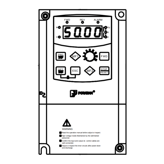
- Page 109 Section VII Standard Specifications 7-3. Shape Size 7-3-1. PI8600 Series ALARM ° C STOP RESET WARNING Read the operation manual before adjust or inspect. High voltage inside.Maintained by the well-trained personnel. Confirm the input and output dc control cables are well connected.
- Page 110 Section VII Standard Specifications 7-3-2. Keyboard Size JP6C8000 Size: DIGITAL PANEL ALARM ℃ STOP/RESET JP6E8000 Size: DIGITAL PANEL ALARM ℃ STOP/RESET...
- Page 111 Section VII Standard Specifications JP6D8000 keyboard rabbet size: the dimension of aperture for installing keyboard in panel: (75.5±0.1)*(122.5±0.1)...
-
Page 112: Inspection And Maintenance
Section VIII Inspection & Maintenance 8-1. Inspection and Maintenance Under normal working conditions, in addition to daily inspection, the frequency converter should be subject to regular inspection (for example inspection for overhaul or as specified but at an interval of six months at most). Please refe r to the following table in order to prevent faults. Check time Check point... - Page 113 第八章 保养与检修 module is damaged. If measuring is necessary, the user should note that much different results will be gained possibly if the measuring is performed with different instruments. It is recommended that the input voltage be measured with pointer-type voltmeter, output voltage with rectification voltmeter, input and output current with tong-test ammeter, and power with electrically-driven wattmeter.
-
Page 114: Appendix I Rs485 Communication Protocol
Appendix I Rs485 communication protocol I-1. Use introduction This chapter introduces something about the install and handle of RS485 communication between inverter and PLC, PC, factory computer. ● Can communicate with all computer. ● Using multi-drop link system, can link more to 127 inverters. ●... - Page 115 Appendix I RS485_S board Assembly drawing ● When using RS232-485 transform, connect Inverter “SG+” to RS485 “T+”, Inverter “SG-” to RS485 “T-”. ● After Confirming connection again, turn on inverter power. ● If connection is right, set communication parameters as following: A29 baud rate 0:1200, 1:2400, 2:4800, 3:9600, 4:19200, 5:38400 A28 current inverter communication address 1~127 (If there are more than 1 inverters, don‟t use the same number);...
- Page 116 Appendix I I-3-2. Definition for communication port B: Communication port B pins Communication 485+ 485- 485+ 485- port B signal White white white white green blue orange Brown EIA/TIA T568A green orange blue brown white white White White EIA/TIA T568B orange blue green...
- Page 117 Appendix I Frame Starter Function code Address Field Data CRC Checksum Frame End The basic format description I-4-1. Start of frame, End of frame interval≧3.5 bytes I-4-2. Slave Address From the machine's local address, through the A28 parameter settings, one network can only one local address uniquely identifed.
- Page 118 Appendix I 0x10=Write multiple function in inverter, at most can be written in 16 registers(register pair of byte) Host Command Frame start Slave Function Register Register Register content Frame end Register content CRC checksum address address code address number byte address ≥3.5 bytes 1 bytes...
- Page 119 Appendix I 0xA4 =0x80+0x24= slave is busy, EEPROM delay. 0xA5 =0x80+0x25= administrator restricted 0xA6 =0x80+0x26= set value is beyond limit. 0xA7 =0x80+0x27= CRC checksum error 0xA8 =0x80+0x28= frame format error I-4-4. Register Address: The register address includes two bytes, data setting is constituted by a two-byte. Function code Register Address high byte Register Address low byte...
- Page 120 Appendix I inverter.single parameter Parameter serial number function.code 0x00 0~63 parameter,only write RAM 0x01 0~63 0x10.write 0x02 0~71 inverter 0x03 0~55 multiple function.code 0x04 0~15 parameter, only write RAM 0x05 0~15 0x06 0~23 0x07 0~47 0x08 0~23 NOTE 1 0x09 0~23 Command Command number...
- Page 121 Appendix I Reserved Stop Running status Reverse Direction status Forward Stop Acceleration Speed up 5,4 status Deceleration Uniform speed Upper frequency Upper not arrive frequency Arrive Lower frequency Lower frequency Arrive No JOG running running JOG running Reserved Reserved Reserved Confirmed fault Fault...
- Page 122 Appendix I Invalid DI4 input Valid Invalid DI5 input Valid Invalid DI6 input Valid Invalid DI7 input Valid Invalid DI8 input Valid Invalid AI1 input Valid Invalid AI2 input Valid Invalid AI3 input Valid Invalid O1 input Valid Invalid O2 input Valid Output.terminal 0x02...
- Page 123 Appendix I E.OL Over load E.UL Under load warming E.PHI Phase loss E.EEP EEPROM error E.ntC Over heat E.dAt Time limit fault E.Set External fault Reserved Reserved Reserved E.PId PID regulation fault E.OHt Motor over heat fault E.OL2 Motor over load fault E.PG PG error E.PHo...
- Page 124 Appendix I Reserved Reserved Reserved Reserved Reserved Reserved Reserved Reserved Invalid DI1 input Valid Invalid DI2 input Valid Invalid DI3 input Valid Invalid DI4 input Valid Invalid DI5 input Valid Invalid Input.terminal 0x01 DI6 input function Valid Invalid DI7 input Valid Invalid DI8 input...
- Page 125 Appendix I Valid Invalid O3 output Balid Invalid O4 output Valid NOTE 1: 0x06/0x10 writing Function 0x03 reading operation operation y00 reset the factory setting Return 0 Only can write into 5 y01 upload parameter Return 0 Invalid operation onto keyboard y02 latest fault record Valid operation Invalid operation...
- Page 126 Appendix I 7 bit 6 bit 5 bit 、 4 bit 0:Lower frequency 0:Upper frequency 00:Stopping 01:Accelerating not arriving not arriving Neaning 10:Decelerating 11:Running in a even 1:Arrive lower 1:Arrive upper speed frequency frequency 3 bit 2 bit 1 bit 0 bit 0:Running reverse 0:Stopping...
- Page 127 Appendix I Reserve Reserve E.PId PID regulation fault E.OHt Motor over heat fault E.OL2 Motor over load fault E.PG PG error E.PHo Inverter output loss phase E.COA Rs485 communication port A fault E.COb Rs485 communication port B fault E.CAL Parameter indentification fault NOTE 5:Fault funning status LED first position LED second position...
- Page 128 Appendix I if(crc_result&0x01) crc_result=(crc_result>>1)^0xa001; else crc_result=crc_result>>1; crc_result=((crc_result&0xff)<<8)|(crc_result>>8); return(crc_result); I-5. Example of communication protocol: Valid setup and communications under normal circumstances, the host command and slave responses are as follows: 0x03= read inverter multiple function code, at most can read 16 registers (register 2bytes) Host command read inverter F01 keyboard set frequency、F02 frequency set up method Slave address Function code Register address...
- Page 129 Appendix I Register content byte number=2 bytes * register number Slave response Slave address Function code Register address Register number CRC checksum 0x08 0x10 0x0001 0x0002 0x1091 0x01=read multiple switch status Host command read inverter whether arrive lower frequency, or arrive upper frequency Slave address Function code Starter to end address Switch number CRC checksum...
-
Page 130: Appendix Ii Instruction Of The Proportional Linkage Function
Appendix II Instruction of the Proportional Linkage Function II-1. Proportional linkage function: The proportion interaction host computer: Communication address = 128, Communications port A is the communication port of host computer. Communication port B can be used as the keyboard interface, or a PC host computer interface. There is only one host inverter in one proportional linkage. - Page 131 Appendix II PID regulation mode The main setting individual control The auxiliary setting individual control main + auxiliary relationship between main and main -auxiliary auxiliary frequencies (main *auxiliary)/maximum frequency Maximum{main, auxiliary} Minimum{main, auxiliary} Running control mode Proportional linkage control Select this function, the slave inverter will follow the command of host inverter to run.
- Page 132 Appendix II 6: The slave actual frequency = F01 + slave potentiometer adjusting + A40 The proportional linkage host settings: Frequency main set mothod AI2 external analog setting Communication address Host 128 Baud rate 3: 9600bps Communication format DI1 input terminal function select selection 1:forward running DI2 input terminal function select 2:reverse running...
- Page 133 Appendix II System wire connections: ALARM ° C S TOP R E S ET ALARM ° C S TOP R E S ET ALARM ° C S TOP R E S ET...
-
Page 134: Appendix Iii Pg Card Instruction
Appendix III PG Card Instruction III-1. Use range Type Encoder output method +5V LINE DRIVER output OPEN COLLECTOR output Push-pull output type (complementary) Voltage output type VOLTAGE III-2. Terminal function instruction terminal Terminal function PG signal input Encoder output method: 1 : +5V LINE DRIVER output;... - Page 135 Appendix III PGND Encoder Encoder PG pulses range 300~9999 Maximum pulses frequency receiver 1MHz,when PG pulses=2500,maximum speed=400Hz III-3. Terminal connection instruction: MCCB Motor R(L1) U(T1) S(L2) V(T2) PI8600 T(L3) W(T3) Inverter Earthing Earthing ( Power ) ( Motor ) Earthing PGND P18000 Aout...
-
Page 136: Appendix Iv Extend Functions Supplement
Appendix IV Extend Functions supplement Parameter Reference Number E00 function definition setting page Inverter power Special power Stable voltage power supply Constant current power Constant pressure Pump constant pressure water water supply supply Extruding machine Extruding machine Extend function instruction have not been fully listed, any query, please directly inquiry to our technician. IV-1. - Page 137 Appendix IV IV-1-2. E00=13: Voltage regulation power In this mode,connect AI2,AI3 to Hall,then measure the output voltage and use2Halls to do redundant work to ensure the output voltage will not exceed the Hall voltage limitation. In this mode, the following parameters should be adjusted: PID function group, P02 PID feedback signal selection.
- Page 138 Appendix IV E12 set to multi-pump,need constant pressure water supply interface board , while realize 4- pumps constant pressure water supply function. 2、PID adjusting in constant water supply system Parameter Keyboard display Setting Meaning Keyboard set frequency Keyboard set the frequency 0hz Frequency main set Keyboard set frequency or RS485 set frequency.
- Page 139 Appendix IV Parameter Keyboard display setting Meaning According to first start first stop principles to Timing shift alternation con - - trol pump rotation,rotation time of 0.25 0.25 time hours When set up a station pump (drive motor) to switch from variable frequency industry frequ - electromagnetic ency, or from industry frequency to variable 0.500...
- Page 140 Appendix IV IV-2-2. Application It is special appendix for multiple pumps, which run with PI7000 family inverter to control the multiple pumps water supply system effectively. IV-2-3. Operation and connection notice: ※ If it is power frequency motor, probable thermal relay must be used to protect motor. ※...
- Page 141 Appendix IV 2. Dimension of water supply controller fixed plate fixed plate fixed plate × the size of fixed plate Note: The fixed plate can be fixed by any mounting hole in the figure.
- Page 142 Appendix IV IV-2-5. Frequency of water supply connection to the drive controller Connection of water supply controller with inverter, the communniction cable and power cable are connected as below:...
- Page 143 Appendix IV IV-2-6. System diagram Remarks: ZK air switch KM contactor JR thermo-relay M motor IV-2-7. Water supply control mode When several pumps supply water meanwhile, because of the different time(daytime and night), different season(winter and summer), the variation of the water flow is great. To save energy and protect the equipment, please run pumps as many as you need and stop pumps as many as you do not need.
- Page 144 Appendix IV controlled soft-start pump start and stop. Soft-start pump terminal control, stop first. Soft-start pump is not controlled by constant pressure water supply system.Soft-start pump can be used as sewage pumps and fire pumps. IV-2-9. Application Guide 3 Pumps constant pressure water supply + sewage pump a) pump configurations: variable frequency pump 3 units, 15kW,1 unit sewage pump,15kW.
- Page 145 Appendix IV ①loading types with a constant pressure water supply function: Parameter Keyboard display setting Meaning Multi-pump constant pressure water supply, need constant pressure water supply interface Loading type board, while realize 4 pump constant pressure water supply pump function. ②PID adjust in constant pressure water supply Parameter Keyboard display...
- Page 146 Appendix IV high pressure reached value of this parameter, the I / O output terminal select 25, then it will output arrival signal. when feedback pressure less than the low pressure reached value of this parameter, the I Low pressure arrival / O output terminal select 26, then it will output arrival signal.
- Page 147 Appendix IV (DI3) input terminal Manual rotation command function selection (DI4) input terminal Timing of water supply time-zero function selection (DI5) input terminal Pump 3 soft starting function selection (DI6) input terminal Pump 3 stopping function selection...
- Page 149 Powtran frequency inverter failure feedback form Dear Customers, in order to provide better service for you, please kindly complete the following form in details: Load and controls Motor Frequency range Motor rated power under normal current and poles working □ Fan □...
- Page 150 .we hope to learn about your present and future demand for powtran products and also your valuable feedback on our products. In order to help you get our service faster and more convenient, please visit our company web site http://www.powtran.com and refer to column "technologies and services"...
Need help?
Do you have a question about the PI8600 Series and is the answer not in the manual?
Questions and answers