Table of Contents
Advertisement
Thank you for choosing Powtran PI500-S Series Solar inverter. This
product made by Powtran is based on years of experience in professional
production and sale, and designed for variety of industrial machinery, fan and
water pump drive unit and IF heavy-duty grinding unit.
This manual provides user the relevant precautions on installation,
operational parameter setting, abnormal diagnosis, routine maintenance and
safe use. In order to ensure correct installation and operation of the frequency
converter, please carefully read this manual before installing it.
For any problem when using this product, please contact your local dealer
authorized by this company or directly contact this company, our professionals
are happy to serve you.
The end-users should hold this manual, and keep it well for future
maintenance & care, and other application occasions. For any problem within
the warranty period, please fill out the warranty card and fax it to the our
authorized dealer.
The contents of this manual are subject to change without prior notice. To
obtain the latest information, please visit our website.
For more product information, please visit: http:// www.powtran.com.
Foreword
Powtran
January, 2018
Advertisement
Table of Contents

Related Manuals for Powtran PI500-S Series


Summary of Contents for Powtran PI500-S Series
- Page 1 Foreword Thank you for choosing Powtran PI500-S Series Solar inverter. This product made by Powtran is based on years of experience in professional production and sale, and designed for variety of industrial machinery, fan and water pump drive unit and IF heavy-duty grinding unit.
-
Page 2: Table Of Contents
Contents Chapter 1.Inspection and safety precautions ..............1 1-1. Inspection after unpacking ................... 1 1-1-1. Instructions on nameplate ................. 1 1-1-2. Model designation .................... 1 1-2. Safety precautions ......................2 1-3. Precautions ........................3 1-4. Scope of applications ....................5 Chapter 2 Standard specifications .................. - Page 3 7-1. Dimension ......................... 59 7-1-1. Product outside drawing, installation size ............. 59 7-1-2. PI500 series ....................59 7-1-3. PI500-S series (With DC reactor base) ............63 7-1-4. Keypad dimension drawing ................64 Chapter 8 Maintenance and repair ................. 66 8-1. Inspection and maintenance ..................66 8-2.
-
Page 5: Chapter 1.Inspection And Safety Precautions
For any problem, please contact your local authorized POWTRAN dealer or directly contact this company. 1-1. Inspection after unpacking ※... -
Page 6: Safety Precautions
Chapter 1.Inspection and safety precautions 1-2.Safety precautions Safety precautions in this manual are divided into the following two categories: Danger: the dangers caused by failure to perform required operation, may result in serious injury or even death; Caution:the dangers caused by failure to perform required operation, may result in moderate injury or minor injury, and equipment damage;... - Page 7 Chapter 1.Inspection and safety precautions inverter, this product has been tested before leaving factory. Otherwise it may cause an accident! ● The inverter's cover plate must be closed before power on. Otherwise it may cause an electric shock! ● Wiring of all external accessories must comply with the guidance of Danger this manual, please correctly wiring in accordance with the circuit connection methods described in this manual.
- Page 8 Chapter 1.Inspection and safety precautions inside inverter or install thermal relay in the front of motor for motor protection. The inverter output frequency rang is 0Hz to 3200Hz(Max.vector Run over power control only supports 300Hz). If the user is required to run at 50Hz or frequency more, please consider the endurance of your mechanical devices.
-
Page 9: Scope Of Applications
Chapter 1.Inspection and safety precautions 3) The inverter has built-in the adaptive motor standard parameters, according to the actual situation, please identify motor parameters or accordingly modify the default values to try to meet the actual value, otherwise it will operation affect and protection performance; 4) When short-circuit of cable or motor internal will activate the inverter alarm, even bombing. -
Page 10: Chapter 2 Standard Specifications
Chapter 2 Standard specifications 2-1.Technical specifications Rated output Rated input Rated output Adaptive Model power(kW) current(A) current(A) motor(kW) Single phase AC 220V± 10%;Recommend DC 200~440V PI500-S 0R4G1 PI500-S 0R7G1 0.75 0.75 PI500-S 1R5G1 PI500-S 2R2G1 PI500-S 004G1 PI500-S 5R5G1 Three phase AC 220V± 10%;Recommend DC 200~440V PI500-S 0R4G2 PI500-S 0R7G2 0.75... -
Page 11: Standard Specifications
Chapter 2 Standard specifications PI500-S 110G3 PI500-S 132G3 PI500-S 160G3 PI500-S 187G3 PI500-S 200G3 PI500-S 220G3 PI500-S 250G3 PI500-S 280G3 PI500-S 315G3 PI500-S 355G3 PI500-S 400G3 Note: the power of solar cell components is recommended to be more than 1.2 times the solar inverter. - Page 12 Chapter 2 Standard specifications regulation(AVR) electricity grid changes Maximum light power tracking, light and weak auto sleep, light Solar pump inverter intensity automatic awakening, high water level automatic stop, low special function water level automatic operation, under-load protection, etc Self-inspection of After powering on, peripheral equipment will perform safety testing, peripherals after such as ground, short circuit, etc.
- Page 13 Chapter 2 Standard specifications Overvoltage protection, undervoltage protection, overcurrent protection, overload protection, overheat protection, overcurrent stall Inverter protection protection, overvoltage stall protection, losing phase protection (optional), communication error, PID feedback signal abnormalities, PG failure and short circuit to ground protection. IGBT temperature Displays current temperature IGBT display...
-
Page 14: Chapter 3 Keyboard
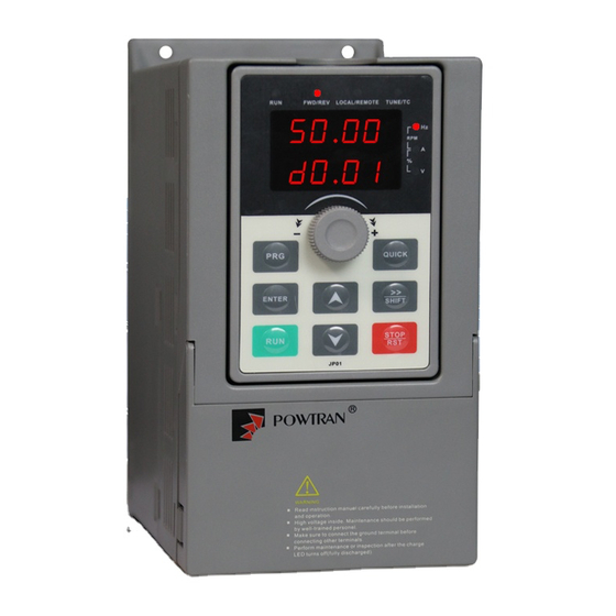
Chapter 3 Keyboard 3-1.Keyboard description Figure 3- 1 Operation panel display 3-2.Keyboard indicators Indicator flag Name Running indicator light * ON: the inverter is working * OFF: the inverter stops Command indicator light That is the indicator for keyboard operation, terminal operation and LOCAL/R remote operation (communication control) EMOTE... -
Page 15: Description Of Operation Panel Keys
Chapter 3 Keyboard 3-3.Description of operation panel keys Sign Name Function Parameter * Enter into the modified status of main menu Setting/Esc * Esc from functional parameter modification * Esc sub-menu or functional menu to status menu *Choose displayed parameter circularly under running or stop interface;... -
Page 16: Examples Of Parameter Settings
Chapter 3 Keyboard 3-5.Examples of parameter settings 3-5-1.Instructions on viewing and modifying function code PI500-S inverter’s operation pane is three levels menu for parameter setting etc.Three levels: function parameter group (Level 1)→function code(level 2)→function code setting(level 3). The operation is as following. Power-on Shutdown parameter display Change parameter group... -
Page 17: The Way To Read Parameters In Various Status
Choose vector control, one must input the motor’s parameters in the nameplate accurately before running the inverter. PI500-S series Solar inverter will match the motor’s standard parameters according to its nameplate. The vector control is highly depend on motor’s parameters. -
Page 18: Chapter 4 Installation And Commissioning
A≥300mm;B≥50mm 90~160kW PI500-S Series Solar inverter heat radiator circulated from bottom to top, when more than one inverter work together, usually mounted side by side. In the case of the need to install them by upper and lower rows, due to the heat of the lower inverters rising to the upper equipment, fault... -
Page 19: Wiring Diagram
Chapter 4 Installation and commissioning Deflector Cool wind Hot wind Figure 4-2 Heat insulation deflector up and down installation diagram 4-3.Wiring Diagram Solar inverter wiring is divided by main circuit and control circuit. Users must properly connect Solar inverter in accordance with the wiring connection diagram showing below. 4-3-1Function description of main circuit terminal Terminal Name... - Page 20 Chapter 4 Installation and commissioning Category Symbol Name Function input terminal jumpers , PLC must be connected to external power supply, and to +24V (default). 1.Input range:(DC 0V to 10V/0 to 20mA), depends on the AI1- Analog input selected AI1 jumper on control panel. 2.Input impedance: 20kΩ...
- Page 21 Chapter 4 Installation and commissioning Category Symbol Name Function inspectio n input 485 differential 485 communication interface, 485 differential signal 485+ signal + terminal, use twisted-pair or shielded wire connect to the terminal Built-in standard 485 communication interface RS485 485 differential 485 jump line in the control panel to decide whether to 485- signal -...
-
Page 22: Wiring Diagram
Chapter 4 Installation and commissioning 4-3-3Wiring diagram Main Circuit Control Circuit Figure 4-3 Wiring diagram... - Page 23 Chapter 4 Installation and commissioning 1. Wiring in accordance with the wiring diagram and closing the switch Q1 after checking the corrected wiring. Note: the AC power and photovoltaic power can not simultaneously supply power to the inverter, can only choose one from them. 2.
- Page 24 Chapter 4 Installation and commissioning E3.02 = 3 (three-wire operation control); E3.05 = 00100; E0.00 = 2 (MPPT mode); After setting the parameters, press the RUN key, Solar inverter runs. If water reaches the high lever detection point, the Solar inverter will free stop. When the water level falls below the low level detection point, the Solar inverter automatically starts running.
-
Page 25: Wiring Precautions
Chapter 4 Installation and commissioning Solar inverter Water tower U V W Water well Start check point Water pump Low level detection points Figure 4-6 Parameters setting: F0.03=8(PV setting); F0.11=4(keyboard+ terminals+ Communications); F1.00=1(forward run); F1.01=8(freewheel); F1.10=2(three-wire mode 1); F1.40=1(input terminal can repeat the definitions); E3.02=3(three-wire operation control);... - Page 26 Chapter 4 Installation and commissioning absorption device shall be installed additionally when electromagnetic contactor and relay is closer from the inverter. External control lines of inverter shall adopt isolation device or shielded wire. In addition to shielding, the wiring of input command signal should also be aligned separately, it is best to stay away from the main circuit wiring.
-
Page 27: Commissioning
Chapter 4 Installation and commissioning 4-5.Commissioning Commissioning Select control mode setting F0.00) 0 Vector control Correctly motor W/O PG F0.00=? parameters(Set b0.00-b0.05 2 V/F control Select suitable frequency Select command Select appropriate ac/deceleration source(Set F0.03) source(Set F0.11) time(Set F0.13,F0.14) Motor parameter Select motor start-up self-learning(Set b0.27) mode(Set F3.00) -
Page 28: Chapter 5 Function Parameter
PI500-S series Solar inverter, some parameters is "manufacturers retain", the serial number in the function parameter list is not listed, resulting in some of the parameters of the table number is not connected, For the parameters not described in the manual, please do not try to modify to avoid causing errors. -
Page 29: F0 Group -Basic Function Group
Chapter 5 Function parameter setting d0.00 Running frequency Actual output frequency 0.01Hz d0.01 Set frequency Actual set frequency 0.01Hz d0.02 DC bus voltage Detected value for DC bus voltage d0.03 output voltage Actual output voltage d0.04 output current Effective value for Actual motor current 0.01A d0.05 output power... - Page 30 Chapter 5 Function parameter V/F control 0:Vector control without PG Refers to the open-loop vector control for high-performance control applications typically , only one inverter to drive a motor. 1:Reserved 2:V/F control Suitable for less precision control applications, such as fan and pump loads. Can be used for an inverter drives several m`otors occasions.
-
Page 31: F1 Group - Input Terminals Group
Chapter 5 Function parameter Maximum output ★ F0.19 50.00Hz~320.00Hz 50.00Hz frequency F0.21 setting Analog AI1 setting Analog AI2 setting Upper limit ★ F0.20 Panel potentiometer setting frequency source High-speed pulse setting Communication reference Analog AI3 setting Setting upper limit frequency. The upper limit frequency can be set from either digital setting (F0.21) or analog input channels. - Page 32 Chapter 5 Function parameter ★ F1.05 DI6 terminal function selection ★ F1.06 DI7 terminal function selection ★ F1.07 DI8 terminal function selection Seting Functions Description value The terminal for not use can be set to "no function" to prevent No function accidental operation.
- Page 33 Chapter 5 Function parameter K1 K2 Command DIx Forward (FWD) Stop DIy Reverse (REV) COM Digital common Stop terminals 1:Two-wire type 2 In the mode, DIx terminal is used as running enabled, while DIy terminal is used to determine running direction. The terminal function is set as follows: Terminals Set value...
-
Page 34: F2 Output Terminal Group
Chapter 5 Function parameter DIx, the motor direction signal is generated by DIy status To stop, you must disconnect DIn terminal signals Of which, DIx, DIy and DIn are the multi- function input terminals of DI1 to DI10, DIx is for active pulse, DIy and DIn are for active level. Forward run FWD Three-wire operation Command... - Page 35 Chapter 5 Function parameter As a high-speed pulse output, the maximum frequency of the output pulse is 100kHz, high- speed pulse output of the correlation function refer to Note F2.06. Switching quantity output function ☆ F2.01 selection (Open collector output 0~40 terminal) Relay 1 output function selection...
- Page 36 Chapter 5 Function parameter When the operating frequency reaches the upper Upper frequency arrival frequency, output ON signal. When the operating frequency reaches the lower The lower frequency arrival frequency, output ON signal. The next stop status signal is (no output when shutdown) OFF.
- Page 37 Chapter 5 Function parameter Analog Output DA1 and DA2 output range is 0V ~ 10V, or 0mA ~ 20mA. Pulse output or analog output range, with the corresponding scaling function relationship in the following table: Setting Functions Description value Running frequency 0~Max.
-
Page 38: F3 Group Start And Stop Control Group
Chapter 5 Function parameter 5-1-5.F3 Group Start and stop control group Factory Change Code Parameter name Setting range setting Limit Direct startup Speed tracking restart ☆ F3.00 Start-up mode Pre-excitation start (AC asynchronous motor) ☆ F3.03 Start frequency 0.00Hz~10.00Hz 0.00Hz ★... -
Page 39: F6 Keyboard And Display
Chapter 5 Function parameter This parameter is valid only for asynchronous motors. V/F slip compensation can compensate for the speed deviation of asynchronous motor when the load increases, so as to keep stable speed when the load changes. If V/F slip compensation gain is set to 100.0%, it means that the compensated deviation is equal to the rated motor slip under the rated motor load mode, while the rated motor slip can be calculated through b0 group of motor rated frequency and rated speed. - Page 40 Chapter 5 Function parameter (Hz) Set frequency Length PLC range Bus voltage (V) Load speed DI input status DO output status PID setting AI1 Voltage (V) High-speed pulse input frequency(Hz) AI2 Voltage (V) Reverse AI3 Voltage (V) Reverse Reverse Numerical value If the above parameters need to be displayed on operation, firstly set its position to 1, and then set at F6.03 after converting the binary number to the hexadecimal number.
-
Page 41: F7 Group Auxiliary Function
Chapter 5 Function parameter shift key forward/Reverse running switching UP/DOWN setting remove Free stop commands switch orderly 1:Jog running: press QUICK key , the inverter will make jog running in the default direction. 2:Shift key : Choose displayed parameter circularly under running or stop interface 3:Forward/Reverse running switching: it can complete the request of forward/Reverse running, it is effective under the keyboard command. - Page 42 Chapter 5 Function parameter large,otherwise the poor inhibitory effect may cause over current fault. When the overcurrent stall gain is set to 0,the overcurrent stall function will be canceled. prohibit ☆ F8.02 Motor overload protection allow ☆ F8.03 Motor overload protection gain 0.20~10.00 1.00 F8.02=0: no motor overload protection function,there may be the risk of the demage to the...
-
Page 43: Communication Parameterf9.00
Chapter 5 Function parameter ☆ F8.10 Auto reset times 0~32767 32767 When the frequency converter chooses to reset the fault automatically, it is used to set the number of automatic reset. After more than this frequency, the converter remains in a state of failure. - Page 44 Chapter 5 Function parameter 208300BPS 256000BPS 512000BPS Hundreds digit Reserved Thousands digit CAN bus baudrate This parameter is used to set the data transfer rate between the host computer and the inverter. Note that the baud rate set by the host computer and the inverter must be the same, otherwise communication can not be working .
-
Page 45: Fb Control Optimization Parameters
Chapter 5 Function parameter PPO3 format PPO5 format F9.05 = 1: Select the standard Modbus protocol,F9.05 = 0: When reading a command, the slave returns more bytes than the standard Modbus protocol. 0.01A Communication read current ☆ F9.06 resolution 0.1A Used to determine the output current value when the communication reads the output current. - Page 46 Chapter 5 Function parameter 2: MPPT mode Bus voltage is given as the maximum power search result, F0.03 is set to 8, photovoltaicmode. When starting but before the searching, the bus voltage is given as E0.01, atintervals after the search, the search result is as given value Confirmed ☆...
-
Page 47: E2 Pid Function Parameter
Chapter 5 Function parameter Confirmed ☆ E0.08 Solar hibernation voltage 0.0~1000.0V model type When inverter is running, when the bus voltage is lower than the set voltage (E0.08),inverter will go into hibernation. Voltage Hibernation voltage default Value(V) 220V 380V ☆ E0.09 Hibernation frequency 0~Max frequency(F0.19) 15.00Hz... - Page 48 Chapter 5 Function parameter E2.10 is used for filtering the PID output frequency, the filter will weaken the sudden change of the inverter output frequency, but it will also bring the response performance of the process closed loop system. 0.0%: not judged feedback loss ☆...
-
Page 49: E3 Virtual Terminal Group
Chapter 5 Function parameter two groups of PID parameters Units digit Integral separation Invalid Valid ☆ E2.22 PID integral properties whether stop integration when Tens digit output reaches limit Continue Stop integral Integral separation:If the integral separation is set to active, when the integral pause of multifunction digital DI(function 38) is active, PID integral will stop operations, at the time only the proportional and derivative actions of PID is active.If the integral separation is set to inactive, however the multifunction digital DI is active or inactive, the integral separation will be inactive. - Page 50 Chapter 5 Function parameter ★ E3.03 Virtual VDI4 terminal function selection 0 to 50 ★ E3.04 Virtual VDI5 terminal function selection 0 to 50 Virtual VDI1 ~ VDI5 on the function, are exactly as same as the DI on the control panel, can be used as a multi-function digital quantity input, the details please refer to the F1.00 ~ F1.09 is introduced.
-
Page 51: B0 Motor Parameter Group
Chapter 5 Function parameter selection of DI High level effectively Tens digit AI2(same as units digit) Hundreds digit AI3(same as units digit) This group function code is used when using AI as DI, when AI used as DI, and input voltage of AI is greater than 7V, AI terminal status will be high level, when input voltage of AI is lower than 3V, AI terminal status will be low level. - Page 52 Chapter 5 Function parameter ★ b0.04 Rated frequency 0.01Hz to F0.19(maximum frequency) ★ b0.05 Rated speed 1rpm to 36000rpm Above b0.00 to b0.05 are the motor nameplate parameters, which affects the accuracy of the measured parameters. Please set up according to the motor nameplate parameters. The excellent vector control performance needs the accurate motor parameters.
-
Page 53: Y0 Function Code Management
Chapter 5 Function parameter Before preforming asynchronous motor parameters comprehensive auto tuning, not only motor type and motor nameplate parameters b0.00 to b0.05 must be set properly, but also encoder type and encoder pulses b0.29, b0.28. For asynchronous motor parameters comprehensive auto tuning, the inverter can obtain b0.06 to b0.10 five motor parameters, as well as the AB phase sequence b0.31 of encoder, vector control current loop PI parameters F5.12 to F5.15. - Page 54 Chapter 5 Function parameter ● y1.00 Type of the first fault 0 to 51 ● y1.01 Type of the second fault 0 to 51 ● y1.02 Type of the third(at last) fault 0 to 51 Record the type of the last three faults of inverter, 0 for no fault. Please refer to the related instructions for the possible causes and solutions for each fault code.
- Page 55 Chapter 5 Function parameter y1.08 Reserved ● y1.09 Power-on time of the third fault Current power-on time of the last fault ● y1.10 Running time of the third fault Current running time of the last fault y1.11 Reserve y1.12 Reserve ●...
- Page 56 Chapter 5 Function parameter When the output terminal is ON, the corresponding binary bits is 1, OFF is 0, all DI status is converted to the decimal number for display. y1.28 Reserved ● y1.29 Power-on time of the first fault Current power-on time of the last fault ●...
-
Page 57: Chapter 6 Troubleshooting
Chapter 6 Troubleshooting 6-1.Fault alarm and countermeasures PI500-S can provide effective protection when the equipment performance is played fully. In case of abnormal fault, the protection function will be invoked, the inverter will stop output, and the faulty relay contact of the inverter will start, and the fault code will be displayed on the display panel of the inverter. - Page 58 Chapter 6 Troubleshooting No. Fault ID Failure type Possible causes Solutions 1.the short-circuit or earthing of inverter output happens 1.eliminate peripheral faults 2.the control mode is vector and 2.perform identification for the without identification of motor parameters parameters 3.set the voltage to the normal Constant speed Err.04 3.the voltage is low...
- Page 59 Chapter 6 Troubleshooting No. Fault ID Failure type Possible causes Solutions 1.the drive panel is abnormal. 1.replace the drive, the power 2.the lightning protection plate is board or contactor abnormal 2.seek for technical support Input phase 12 Err.12 3.the main control panel is 3.check and eliminate the loss abnormal...
- Page 60 Chapter 6 Troubleshooting No. Fault ID Failure type Possible causes Solutions Cumulative Clear history information by Cumulative running time arrival 26 Err.26 running time using initialization function fault arrival fault parameters Input custom fault 1 signal 27 Err.27 Custom fault 1 through the multi-function Reset run terminal DI...
-
Page 61: Emc (Electromagnetic Compatibility)
Chapter 6 Troubleshooting 6-2.EMC (Electromagnetic Compatibility) Electromagnetic compatibility refers to the ability that the electric equipment runs in an electromagnetic interference environment and implements its function stably without interferences on the electromagnetic environment. 6-2-1EMC standard In accordance with the requirements of the Chinese national standard GB/T12668.3, the inverter must comply with the requirements of electromagnetic interference and anti- electromagnetic interference. -
Page 62: Remedies For The Interference From The Inverter To The Surrounding
Chapter 6 Troubleshooting 6-3-4.Remedies for the interference from the inverter to the surrounding electromagnetic equipment These noise interference are classified into two types: one is the radiation interference of the inverter, and the other is the conduction interference of the inverter. These two types of interference cause that the surrounding electric equipment suffer from the affect of electromagnetic or electrostatic induction. -
Page 63: Chapter 7 Dimension
Chapter 7 Dimension 7-1.Dimension 7-1-1.Product outside drawing, installation size Upper cove plate operation panel Upper cover plate Cooling fan retaining screw Nameplate Cable inlet Air duct inlet Figure 7-1: 15kW G3 above product outside drawing, installation dimension 7-1-2.PI500 series NOTE:0.75~4kW G3 support Rail installation Figure 7-2:0.75~4kW G3Dimension... - Page 64 Chapter 7 Dimension Figure 7-3:5.5~11kW G3 Dimension Moulded shell series: Guide rail Weight Output (kg) Dimension (mm) Installation(mm) installation Power rating power position (kW) PI500-S 0R4G1 PI500-S 0R4G2 PI500-S 0R7G1 0.75 PI500-S 0R7G2 0.75 163 185 146 154 72.5 PI500-S 0R7G3 0.75 PI500-S 1R5G2 PI500-S 1R5G3...
- Page 65 Chapter 7 Dimension φd Figure 7-4:15~220kW G3 Dimension φd Figure 7-5:250~400kW G3 Dimension...
- Page 66 Chapter 7 Dimension Iron shell hanging series: Output Dimension (mm) Installation(mm) Weight (kg) Power rating power (kW) PI500-S 5R5G1 PI500-S 7R5G2 280 300 190 190 198 140 PI500-S 015G3 PI500-S 011G2 PI500-S 018G3 18.5 330 350 210 190 198 150 PI500-S 022G3 PI500-S 015G2 PI500-S 018G2...
-
Page 67: Pi500-S Series (With Dc Reactor Base)
Chapter 7 Dimension 7-1-3.PI500-S series (With DC reactor base) Figure 7-6:132~220kW G3 (With DC reactor and base)Dimension Figure 7-7:250~400kW G3 (With DC reactor and base)Dimension... -
Page 68: Keypad Dimension Drawing
Chapter 7 Dimension Iron shell landing installation series Output Dimension (mm) Installation(mm) Weight (kg) Power rating power (kW) PI500-S 132G3R 995 1020 400 360 368 350 270 13*18 PI500-S 160G3R PI500-S 187G3R 1230 1260 480 390 398 400 200 PI500-S 200G3R PI500-S 220G3R PI500-S 250G3R 1419 1460 560 410 418 500 310... - Page 69 Chapter 7 Dimension PI500-S keyboard size chart: 5- ? 4.2 90° Figure 7-9:keyboard size chart (size: mm) PI500-S keyboard installation opening size map: Outside installation panel open Inside installation panel open T=1.0 1.5mm T=1.0 1.5mm inlet dimension Installation Installation inlet dimension panel panel 4-R9...
-
Page 70: Chapter 8 Maintenance And Repair
Chapter 8 Maintenance and repair 8-1.Inspection and maintenance During normal use of the inverter, in addition to routine inspections, the regular inspections are required (e.g. the overhaul or the specified interval, and the interval shall not exceed 6 months), please refer to the following table to implement the preventive measures. Check Date Check Check... -
Page 71: Storage
Chapter 8 Maintenance and repair Name of Parts Standard life time Cooling fan 1 to 3 years Filter capacitor 4 to 5 years Printed circuit board(PCB) 5 to 8 years 8-3.Storage The following actions must be taken if the inverter is not put into use immediately(temporary or long-term storage) after purchasing: ※... -
Page 72: Measuring And Readings
Chapter 8 Maintenance and repair Voltage Inverter AC 380V Figure 8- 1 380V Drive equipment charging circuit example 8-5.Measuring and readings ※ If a general instrument is used to measure current, imbalance will exists for the current at the input terminal. generally, the deviation is not more than 10%, that is normal. If the deviation exceeds 30%, please inform the original manufacturer to replace rectifier bridge, or check if the deviation of three-phase input voltage is above 5V or not. -
Page 73: Chapter 9 Warranty
Chapter 9 Warranty The product quality shall comply with the following provisions: 1. Warranty terms 1-1. The product from the user the date of purchase, the warranty period of 12 months (limited to domestic market). 1-2. Export products and non-standard products warranty period is 12 months or according to the agreement of warranty execution. -
Page 74: Appendix I Recommended Solar Array Configuration
Appendix I Recommended solar array configuration Open-circuit voltage degree of solar module Max. 20± 3V 30± 3V 36± 3V 42± 3V Inverter input power Module Module Module Module Module Module Module Module Module Module curre (kW) power s per power s per power s per... -
Page 75: Appendix Ii Rs485 Communication Protocol
Appendix II RS485 Communication protocol II -1 Communication protocol II -1-1 Communication content This serial communication protocol defines the transmission information and use format in the series communication Including: master polling( or broadcast) format; master encoding method, and contents including: function code of action, transferring data and error checking. The response of slave also adopts the same structure, and contents including: action confirmation, returning the data and error checking etc. - Page 76 Appendix II II -1-3 Protocol description PI500-S -S series inverter communication protocol is a asynchronous serial master-slave communication protocol, in the network, only one equipment(master) can build a protocol (known as “Inquiry/Command”). Other equipment(slave) only can response the "Inquiry/Command"of master by providing data or perform the corresponding action according to the "Inquiry/Command"of master.
- Page 77 Appendix II Byte number high-order Byte number low-order Data F002H high-order Data F002H low-order Data F003H high-order Data F003H low-order CRC CHK low-order CRC CHK values are to be calculated CRC CHK high-order When F9.05is set to 1: Byte number Data F002H high-order Data F002H low-order Data F003H high-order...
- Page 78 Appendix II the most significant bit(MSB) is filled with 0. LSB will be picked up for detection, if LSB is 1, the register will be XOR with the preset value separately, if LSB is 0, then no XOR takes place. The whole process is repeated eight times.
- Page 79 Appendix II the RAM value. If F group parameters need to achieve the function, as long as change high order F of the function code address to 0. If E group parameters need to achieve the function, as long as change high order F of the function code address to 4.
- Page 80 Appendix II The first: Set F0.03 (main frequency source setting) as 0/1 (keyboard set frequency), and then modify the settings frequency by modifying F0.01 (keyboard set frequency). Communication mapping address of F0.01 is 0xF001 (Only need to change the RAM communication mapping address to 0x0001).
- Page 81 Appendix II 0004: Constant speed overcurrent 0005: Acceleration overvoltage 0006: Deceleration overvoltage 0007: Constant speed overvoltage 0008: Control power failure 0009: Undervoltage fault 000A: Inverter overload 000B: Motor Overload 000C: Input phase loss 000D: Output phase loss 000E: Module overheating 000F: External fault 0010: Communication abnormal 0011: Contactor abnormal...
- Page 82 Product information feedback Dear user: Thank you for your interest in and purchasing Powtran products! In order to better serve you, we want to be able to timely get your personal information and the related information of the purchased Powtran products so as to understand your further demands for our Powtran products, we would appreciate your valuable feedback.
Need help?
Do you have a question about the PI500-S Series and is the answer not in the manual?
Questions and answers
How can i resolve the error described by the image below please?
To resolve an error on the Powtran PI500-S Series inverter, follow these steps:
1. Check the Fault Code: The inverter will display a fault code on its panel when an error occurs.
2. Self-Check: Analyze the fault cause using the troubleshooting instructions in Chapter 6 of the manual.
3. Identify the Cause: Determine whether the fault is due to incorrect installation, parameter settings, or external factors.
4. Apply the Recommended Solution: Follow the corresponding countermeasures provided in the manual.
5. Restart the Inverter: After resolving the issue, reset the inverter and check if the fault persists.
6. Contact Support if Needed: If the issue is unresolved, reach out to an authorized dealer or the manufacturer for assistance.
These steps help diagnose and fix errors efficiently.
This answer is automatically generated
F00 OC-P OCFA
The inverter hangs at a certain speed,what could be the problem
The Powtran PI500-S Series inverter could hang at a certain speed due to the following reasons:
1. Peripheral Faults – A short circuit or grounding issue in the inverter output.
2. Incorrect Control Mode – If the control mode is set to vector control without proper motor parameter identification.
3. Low Voltage – The input voltage might be too low.
4. Sudden Load Increase – A sudden increase in load while running.
5. Inverter Power Selection – The inverter's power level might be too small for the application.
To resolve the issue, check for short circuits, ensure correct motor parameter identification, set the voltage to the normal range, avoid sudden load increases, and choose an inverter with a sufficient power level.
This answer is automatically generated